
Coding for Neon
Non-Confidential
Issue 04
Copyright © 2020 Arm Limited (or its affiliates).
All rights reserved.
102159

Coding for Neon
102159
Issue 04
Copyright © 2020 Arm Limited (or its affiliates). All rights reserved.
Non-Confidential
Page 2 of 46
Coding for Neon
Copyright
©
2020 Arm Limited (or its affiliates). All rights reserved.
Release information
Document history
Issue Date Confidentiality Change
01 05 July 2020 Non-Confidential First release
02 17 August 2020 Non-Confidential Second release. Added sections on load and store
leftovers, and permutation instructions.
03 17 September 2020 Non-Confidential
Third release. Added section on matrix multiplication.
04 15 December 2020 Non-Confidential
Fourth release. Added section on shifts.
Non-Confidential Proprietary Notice
This document is protected by copyright and other related rights and the practice or implementation of the
information contained in this document may be protected by one or more patents or pending patent
applications. No part of this document may be reproduced in any form by any means without the express prior
written permission of Arm. No license, express or implied, by estoppel or otherwise to any intellectual property
rights is granted by this document unless specifically stated.
Your access to the information in this document is conditional upon your acceptance that you will not use or
permit others to use the information for the purposes of determining whether implementations infringe any
third party patents.
THIS DOCUMENT IS PROVIDED “AS IS”. ARM PROVIDES NO REPRESENTATIONS AND NO WARRANTIES,
EXPRESS, IMPLIED OR STATUTORY, INCLUDING, WITHOUT LIMITATION, THE IMPLIED WARRANTIES
OF MERCHANTABILITY, SATISFACTORY QUALITY, NON-INFRINGEMENT OR FITNESS FOR A
PARTICULAR PURPOSE WITH RESPECT TO THE DOCUMENT. For the avoidance of doubt, Arm makes no
representation with respect to, and has undertaken no analysis to identify or understand the scope and content
of, patents, copyrights, trade secrets, or other rights.
This document may include technical inaccuracies or typographical errors.
TO THE EXTENT NOT PROHIBITED BY LAW, IN NO EVENT WILL ARM BE LIABLE FOR ANY DAMAGES,
INCLUDING WITHOUT LIMITATION ANY DIRECT, INDIRECT, SPECIAL, INCIDENTAL, PUNITIVE, OR
CONSEQUENTIAL DAMAGES, HOWEVER CAUSED AND REGARDLESS OF THE THEORY OF LIABILITY,
ARISING OUT OF ANY USE OF THIS DOCUMENT, EVEN IF ARM HAS BEEN ADVISED OF THE
POSSIBILITY OF SUCH DAMAGES.
This document consists solely of commercial items. You shall be responsible for ensuring that any use,
duplication or disclosure of this document complies fully with any relevant export laws and regulations to assure
that this document or any portion thereof is not exported, directly or indirectly, in violation of such export laws.
Use of the word “partner” in reference to Arm's customers is not intended to create or refer to any partnership
relationship with any other company. Arm may make changes to this document at any time and without notice.
If any of the provisions contained in these terms conflict with any of the provisions of any click through or
signed written agreement covering this document with Arm, then the click through or signed written agreement
prevails over and supersedes the conflicting provisions of these terms. This document may be translated into
Coding for Neon
102159
Issue 04
Copyright © 2020 Arm Limited (or its affiliates). All rights reserved.
Non-Confidential
Page 3 of 46
other languages for convenience, and you agree that if there is any conflict between the English version of this
document and any translation, the terms of the English version of the Agreement shall prevail.
The Arm corporate logo and words marked with
®
or ™ are registered trademarks or trademarks of Arm Limited
(or its affiliates) in the US and/or elsewhere. All rights reserved. Other brands and names mentioned in this
document may be the trademarks of their respective owners. Please follow Arm's trademark usage guidelines at
http://www.arm.com/company/policies/trademarks.
Copyright
©
2020 Arm Limited (or its affiliates). All rights reserved.
Arm Limited. Company 02557590 registered in England.
110 Fulbourn Road, Cambridge, England CB1 9NJ.
(LES-PRE-20349)
Confidentiality Status
This document is Non-Confidential. The right to use, copy and disclose this document may be subject to license
restrictions in accordance with the terms of the agreement entered into by Arm and the party that Arm
delivered this document to.
Unrestricted Access is an Arm internal classification.
Web Address
www.arm.com
Coding for Neon
102159
Issue 04
Copyright © 2020 Arm Limited (or its affiliates). All rights reserved.
Non-Confidential
Page 4 of 46
Contents
1 Overview ........................................................................................................................................................................ 6
2 Load and store: example RGB conversion ......................................................................................................... 7
3 Load and store: data structures ............................................................................................................................. 9
3.1 Syntax ........................................................................................................................................................................................... 9
3.2 Interleave pattern ............................................................................................................................................................... 10
3.3 Element types ........................................................................................................................................................................ 10
3.4 Single or multiple elements ............................................................................................................................................ 12
3.5 Addressing............................................................................................................................................................................... 13
3.6 Other types of loads and stores ................................................................................................................................... 13
4 Load and store: leftovers ........................................................................................................................................14
4.1 Extend arrays with padding ............................................................................................................................................ 14
4.2 Overlap data elements ...................................................................................................................................................... 15
4.3 Process leftovers as single elements ......................................................................................................................... 17
4.4 Other considerations for leftovers ............................................................................................................................. 19
5 Permutation: rearranging vectors ......................................................................................................................21
5.1 Permutation guidelines .................................................................................................................................................... 21
5.2 Alternatives to permutation .......................................................................................................................................... 21
6 Permutation: Neon instructions ..........................................................................................................................23
6.1 Move instructions ............................................................................................................................................................... 23
6.2 Reverse instructions .......................................................................................................................................................... 24
6.3 Extraction instructions ..................................................................................................................................................... 26
6.4 Transpose instructions ..................................................................................................................................................... 28
6.5 Interleave instructions...................................................................................................................................................... 29
6.6 Table lookup instructions ................................................................................................................................................ 30
7 Matrix multiplication ...............................................................................................................................................32
7.1 The algorithm......................................................................................................................................................................... 32
7.2 Neon registers and data size .......................................................................................................................................... 33
7.3 Floating-point implementation .................................................................................................................................... 34
Coding for Neon
102159
Issue 04
Copyright © 2020 Arm Limited (or its affiliates). All rights reserved.
Non-Confidential
Page 5 of 46
7.4 Fixed-point implementation .......................................................................................................................................... 36
7.5 Optimized instruction scheduling ............................................................................................................................... 37
8 Shifting left and right ...............................................................................................................................................39
8.1 Shifting vectors ..................................................................................................................................................................... 39
8.2 Shifting and inserting ......................................................................................................................................................... 40
8.3 Shifting and accumulation ............................................................................................................................................... 40
8.4 Instruction modifiers ......................................................................................................................................................... 40
8.5 Available shifting instructions ...................................................................................................................................... 42
8.6 Example: converting color depth ................................................................................................................................. 44
8.6.1 Converting from RGB565 to RGB888 .................................................................................................................. 44
8.6.2 Converting from RGB888 to RGB565 .................................................................................................................. 45
8.7 Conclusion ............................................................................................................................................................................... 45
9 Related information .................................................................................................................................................46
Coding for Neon
102159
Issue 04
Copyright © 2020 Arm Limited (or its affiliates). All rights reserved.
Non-Confidential
Page 6 of 46
1 Overview
Arm Neon technology is a 64-bit or 128-bit hybrid Single Instruction Multiple Data (SIMD)
architecture that is designed to accelerate the performance of multimedia and signal processing
applications. These applications include the following:
• Video encoding and decoding
• Audio encoding and decoding
• 3D graphics processing
• Speech processing
• Image processing
This guide provides information about how to write SIMD code for Neon using assembly language.
This guide is written for anyone wanting to learn more about the Armv8-A instruction set
architecture. The following readers should find the information particularly useful:
• Tools developers
• Low-level SoC programmers, such as firmware, device driver, or android kernel developers
• Programmers who want to optimize libraries or applications for an Arm-based target device
• Very keen Raspberry Pi enthusiasts
This guide covers getting started with Neon, using it efficiently, and hints and tips for more
experienced coders. Specifically, this guide deals with the following subject areas:
• Memory operations, and how to use the flexible load and store instructions.
• Using the permutation instructions to deal with load and store leftovers.
• Using Neon to perform an example data processing task, matrix multiplication.
• Shifting operations, using the example of converting image data formats.
Coding for Neon
102159
Issue 04
Copyright © 2020 Arm Limited (or its affiliates). All rights reserved.
Non-Confidential
Page 7 of 46
2 Load and store: example RGB
conversion
This section considers an example task of converting RGB data to BGR color data.
In a 24-bit RGB image, the pixels are arranged in memory as R, G, B, R, G, B, and so on. You want to
perform a simple image-processing operation, like switching the red and blue channels. How can you
do this efficiently using Neon?
Using a load that pulls RGB data items sequentially from memory into registers makes swapping the
red and blue channels awkward.
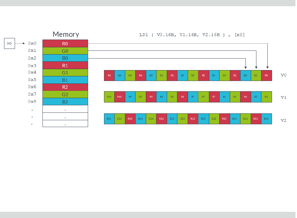
Consider the following instruction, which loads RGB data one byte at a time from memory into
consecutive lanes of three Neon registers:
LD1 { V0.16B, V1.16B, V2.16B }, [x0]
The following diagram shows the operation of this instruction:
Code to swap channels based on this input would be complicated. We would need to mask different
lanes to obtain the different color components, then shift those components and recombine. The
resulting code is unlikely to be efficient.
Neon provides structure load and store instructions to help in these situations. These instructions
pull in data from memory and simultaneously separate the loaded values into different registers. For
this example, you can use the LD3 instruction to separate the red, green, and blue data values into
different Neon registers as they are loaded:
LD3 { V0.16B, V1.16B, V2.16B }, [x0]

Coding for Neon
102159
Issue 04
Copyright © 2020 Arm Limited (or its affiliates). All rights reserved.
Non-Confidential
Page 8 of 46
The following diagram shows how the above instruction separates the different data channels:
The red and blue values can now be switched easily using the MOV instruction to copy the entire
vector. Finally, we write the data back to memory, with reinterleaving, using the ST3 store
instruction.
A single iteration of this RGB to BGR switch can be coded as follows:
LD3 { V0.16B, V1.16B, V2.16B }, [x0], #48 // 3-way interleaved load from
// address in X0, post-incremented
// by 48
MOV V3.16B, V0.16B // Swap V0 -> V3
MOV V0.16B, V2.16B // Swap V2 -> V0
MOV V2.16B, V3.16B // Swap V3 -> V2
// (net effect is to swap V0 and V2)
ST3 { V0.16B, V1.16B, V2.16B }, [x1], #48 // 3-way interleaved store to address
// in X1, post-incremented by 48
Each iteration of this code does the following:
• Loads from memory 16 red bytes into V0, 16 green bytes into V1, and 16 blue bytes into V2.
• Increments the source pointer in X0 by 48 bytes ready for the next iteration. The increment of 48
bytes is the total number of bytes that we read into all three registers, so 3 x 16 bytes in total.
• Swaps the vector of red values in V0 with the vector of blue values in V2, using V3 as an
intermediary.
• Stores the data in V0, V1, and V2 to memory, starting at the address that is specified by the
destination pointer in X1, and increments the pointer.

Coding for Neon
102159
Issue 04
Copyright © 2020 Arm Limited (or its affiliates). All rights reserved.
Non-Confidential
Page 9 of 46
3 Load and store: data structures
Neon structure load instructions read data from memory into 64-bit Neon registers, with optional
deinterleaving.
Structure store instructions work similarly, reinterleaving data from registers before writing it to
memory, as shown in the following diagram:
3.1 Syntax
The structure load and store instructions follow a consistent syntax.
The following diagram shows the general syntax of the structure load and store instructions:
This instruction syntax has the following format:
• An instruction mnemonic, with two parts:
o The operation, either LD for loads or ST for stores.
o A numeric interleave pattern specifying the number of elements in each structure.

Coding for Neon
102159
Issue 04
Copyright © 2020 Arm Limited (or its affiliates). All rights reserved.
Non-Confidential
Page 10 of 46
• A set of 64-bit Neon registers to be read or written. A maximum of four registers can be listed,
depending on the interleave pattern. Each entry in the set of Neon registers has two parts:
o The Neon register name, for example V0.
o An arrangement specifier. This indicates the number of bits in each element and the number
of elements that can fit in the Neon vector register. For example, 16B indicates that each
element is one byte (B), and each vector is a 128-bit vector containing 16 elements.
• A general-purpose register containing the location to access in memory. The address can be
updated after the access.
3.2 Interleave pattern
Neon provides instructions to load and store interleaved structures containing from one to four
equally sized elements. Elements are the standard Neon-supported widths of 8 (B), 16 (H), 32 (S), or
64 (D) bits.
• LD1 is the simplest form. It loads one to four registers of data from memory, with no
deinterleaving. You can use LD1 to process an array of non-interleaved data.
• LD2 loads two or four registers of data, deinterleaving even and odd elements into those
registers. You can use LD2 to separate stereo audio data into left and right channels.
• LD3 loads three registers and deinterleaves. You can use LD3 to split RGB pixel data into
separate color channels.
• LD4 loads four registers and deinterleaves. You can use LD4 to process ARGB image data.
The store instructions ST1, ST2, ST3, and ST4 support the same options, but interleave the data
from registers before writing them to memory.
3.3 Element types
Loads and stores interleave elements based on the size that is specified to the instruction.
For example, consider the following instruction:
LD2 {V0.8H, V1.8H}, [X0]
This instruction loads two Neon registers with deinterleaved data starting from the memory address
in X0. The 8H in the arrangement specifier indicates that each element is a 16-bit halfword (H), and
each Neon register is loaded with eight elements. This instruction therefore results in eight 16-bit
elements in the first register V0, and eight 16-bit elements in the second register V1. Adjacent pairs
(even and odd) are separated to each register, as shown in the following diagram:

Coding for Neon
102159
Issue 04
Copyright © 2020 Arm Limited (or its affiliates). All rights reserved.
Non-Confidential
Page 11 of 46
The following instruction uses the arrangement specifier 4S, changing the element size to 32-bits:
LD2 {V0.4S, V1.4S}, [X0]
Changing the element size to 32-bits loads the same amount of data, but now only four elements
make up each vector, as shown in the following diagram:
Element size also affects endianness handling. In general, if you specify the correct element size to the
load and store instructions, bytes are read from memory in the appropriate order. This means that the
same code works on little-endian systems and big-endian systems.
Finally, element size has an impact on pointer alignment. Alignment to the element size generally
gives better performance, and it might be a requirement of your target operating system. For
example, when loading 32-bit elements, align the address of the first element to at least 32-bits.

Coding for Neon
102159
Issue 04
Copyright © 2020 Arm Limited (or its affiliates). All rights reserved.
Non-Confidential
Page 12 of 46
3.4 Single or multiple elements
In addition to loading multiple elements, structure loads can also read single elements from memory
with deinterleaving. Data can either be replicated to all lanes of a Neon register, or inserted into a
single lane, leaving the other lanes intact.
For example, the following instruction loads a single three-element data structure from the memory
address pointed to by X0, then replicates that data into all lanes of three Neon registers:
LD3R { V0.16B, V1.16B, V2.16B } , [x0]
The following diagram shows the operation of this instruction:
By contrast, the following instruction loads a single three-element data structure into a single lane of
three Neon registers, leaving the other lanes intact:
LD3 { V0.B, V1.B, V2.B }[4] , [x0]
The following diagram shows the operation of this instruction. This form of the load instruction is
useful when you need to construct a vector from data scattered in memory.
Stores are similar, providing support for writing single or multiple elements with interleaving.

Coding for Neon
102159
Issue 04
Copyright © 2020 Arm Limited (or its affiliates). All rights reserved.
Non-Confidential
Page 13 of 46
3.5 Addressing
Structure load and store instructions support three formats for specifying addresses:
• Register (no offset): [Xn]
This is the simplest form. Data is loaded and stored to the address that is specified by Xn.
• Register with post-index, immediate offset: [Xn], #imm
Use this form to update the pointer in Xn after loading or storing, ready to load or store the next
elements.
The immediate increment value #imm must be equal to the number of bytes that is read or
written by the instruction.
For example, the following instruction loads 48 bytes of data, using three registers, each
containing 16 x 1 byte data elements. This means that the immediate increment is 48:
LD3 { V0.16B, V1.16B, V2.16B }, [x0], #48
However, the next example loads 32 bytes of data, using two registers, each containing 2 x 8 byte
data elements. This means that the immediate increment is 32:
LD2 { V0.2D, V1.2D}, [x0], #32
• Register with post-index, register offset: [Xn], Xm
After the memory access, increment the pointer by the value in register Xm. This form is useful
when reading or writing groups of elements that are separated by fixed widths, for example when
reading a vertical line of data from an image.
3.6 Other types of loads and stores
This guide only deals with structure loads and stores. However, Neon also provides other types of
load and store instruction, including:
• LDR and STR to load and store single Neon registers.
• LDP and STP to load or store pairs of Neon registers.
For more details on supported load and store operations, see the Arm Architecture Reference
Manual.
Detailed cycle timing information for the instructions can be found in the Technical Reference
Manual for each core.
Coding for Neon
102159
Issue 04
Copyright © 2020 Arm Limited (or its affiliates). All rights reserved.
Non-Confidential
Page 14 of 46
4 Load and store: leftovers
A common situation when coding for Neon is dealing with input data that is not an exact multiple of
the number of lanes in the vector register.
For example, consider an input array that contains 21 data elements, each of which is a 16-bit integer.
You want to use Neon to process the data in this array. Neon registers are 128 bits wide, so can
process eight lanes of 16-bit data at a time. In two iterations, your Neon code can process 16 (2 x 8)
data elements. However, this leaves five leftover data elements to process in the final iteration. These
five leftover data elements are not enough to completely fill a Neon register.
There are three approaches that you can take to handle these leftovers. Which method to choose
depends on your requirements. The three approaches are as follows, with the fastest approach listed
first:
• Extend arrays with padding
• Overlap data elements
• Process leftovers as single elements
4.1 Extend arrays with padding
If you can change the size of the arrays, you can increase the length of the array to the next multiple of
the vector size using padding elements. This allows you to read and write beyond the end of your data
without corrupting adjacent storage.
In our example with 21 data elements, increasing the array size to 24 elements allows the third
iteration to complete without potential data corruption.
The following diagram shows how the three iterations load eight data elements into the Neon
register. The final iteration loads the three padding elements along with the final five array values:

Coding for Neon
102159
Issue 04
Copyright © 2020 Arm Limited (or its affiliates). All rights reserved.
Non-Confidential
Page 15 of 46
The gray data elements in the diagram represent padding values, and the green data elements are the
original 21 array values.
Be careful to choose padding values that do not affect the result of your calculation. For example:
• If you are summing array values, use a padding value of zero.
• If you are finding the minimum value in an array, use a padding value of the maximum value that
the data element can contain.
It might not be possible to choose a padding value that does not affect the result of your calculation.
For example, when calculating the range of an array of numbers any padding value you choose could
affect the result. In these cases, do not use this method.
Allocating larger arrays consumes more memory. The increase could be significant if many short
arrays are involved.
The following code shows how you could implement a solution that extends arrays with padding:
// Function entry point
// X0 = input array pointer
// X1 = output array pointer
// X2 = number of elements in array
process_array:
ADD X2, X2, #7 // Add (vector register lanes - 1) to the array length
LSR X2, X2, #3 // Divide the length of the array by the number of
// vector register lanes (8) to find the number of
// iterations required.
loop:
LD1 { V0.8H } , [X0], #16 // Load eight elements from the array pointed to
// by X0 into V0, and update X0 to point to the
// next vector
//...
//... Process the data for this iteration
//...
ST1 { V0.8H } , [X1], #16 // Write eight elements to the output array, and
// update X1 to point to next vector
SUBS X2, X2, #1 // Decrement the loop counter and set flags
B.NE loop // Branch back if count is not yet zero...
RET // ... otherwise return
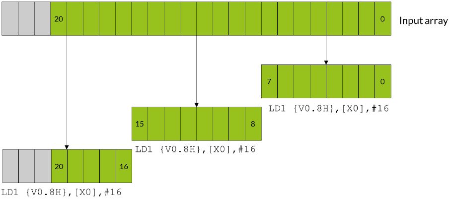
4.2 Overlap data elements
If the operation is suitable, leftover elements can be handled by overlapping those elements.
Overlapping means processing some of the elements in the array twice.
In the example case, the iterations that use overlap would follow these steps:
1. The first iteration processes elements zero to seven.
2. The second iteration processes elements five to 12.
3. The third and final iteration processes elements 13-20.

Coding for Neon
102159
Issue 04
Copyright © 2020 Arm Limited (or its affiliates). All rights reserved.
Non-Confidential
Page 16 of 46
Note that elements five to seven, which are the overlap between the first vector and the second
vector, are processed twice.
The following diagram shows how all three iterations load eight data elements into the Neon register,
with the first and second iterations operating on overlapping vectors:
The blue data elements represent the overlapping elements that are processed twice. The green data
elements are the original 21 array values.
You can only use overlaps when the operation applied to the input data does not vary with the
number of times that the operation is applied. The technical term is to say that the operation must be
idempotent. For example, if you are trying to find the maximum element in an array, you can use
overlaps. This is because it does not matter if the maximum value appears more than once. However,
if you are summing an array, you cannot use overlaps. This is because the overlapping elements would
be counted twice.
The number of elements in the array must fill at least one complete vector.
The following code shows how you could implement a solution that extends arrays with padding:
// Function entry point
// X0 = input array pointer
// X1 = output array pointer
// X2 = number of elements in array
process_array:
ANDS X3, X2, #7 // Calculate number of elements left over after

Coding for Neon
102159
Issue 04
Copyright © 2020 Arm Limited (or its affiliates). All rights reserved.
Non-Confidential
Page 17 of 46
// processing complete vectors using
// array length & (vector register lanes - 1).
LSL X3, X3, #1 // Multiply leftover elements by 2 to get the required
// address increment because we are dealing with doubleword data.
BEQ loopsetup // If the result of the ANDS is zero, the length
// of the data is an exact multiple of the number
// of lanes in the vector register, so there is
// no overlap. Processing can begin.
// Otherwise, handle the first vector separately...
LD1 {V0.8H}, [X0], X3 // Load the first eight elements from the array,
// and update the pointer by the required address increment.
//...
//... Process the data for this iteration.
//...
ST1 {V0.8H}, [X1], X3 // Write eight elements to the output array, and
// update the pointer.
// Now set up the vector processing loop
loopsetup:
LSR X2, X2, #3 // Divide the length of the array by the number of lanes
// in the vector register (8) to find the number of
// iterations required.
// This loop can now operate on exact multiples
// of the lane number. The first few elements of
// the first vector overlap with some of those
// processed earlier.
loop:
LD1 { V0.8H }, [X0], #16 // Load eight elements from the array pointed to
// by X0 into V0, and update X0 to point to the
// next vector.
//...
//... Process the data for this iteration.
//...
ST1 { V0.8H }, [X1], #16 // Write eight elements to the output array, and
// update X1 to point to next vector.
SUBS X2, X2, #1 // Decrement the loop counter and set flags
B.NE loop // Branch back if count is not yet zero...
RET // ... otherwise return
4.3 Process leftovers as single elements
Neon provides load and store instructions that can operate on single elements in a vector. You can
use these instructions to load a partial vector that contains one element, operate on that partial
vector, and then write the element back to memory.
In the example case, the iterations using single elements would follow these steps:
1. The first two iterations execute as normal, processing elements zero to seven, and eight to 15.
2. The third iteration needs only to process five elements. A separate loop handles these elements,
which loads, processes, and stores single elements.

Coding for Neon
102159
Issue 04
Copyright © 2020 Arm Limited (or its affiliates). All rights reserved.
Non-Confidential
Page 18 of 46
The following diagram shows how the first two iterations operate on full vectors, while the leftover
elements are handled individually:
This approach is slower than the previous two methods. This is because each leftover element must
be loaded, processed, and stored individually.
This approach increases code size. Handling leftovers individually requires two loops, one for the full
vectors, and a second loop for the single elements.
Neon single element loads only change the value of the specified lane in the destination element,
leaving the rest of the vector intact. If the calculation that you are performing involves instructions
that work across a vector, the register must be initialized before loading the first single element. For
example, if you were using
ADDV
to sum across the entire vector, initialize the unused lanes to zero.
The following code shows how you could implement a solution that processes leftovers as single
elements:
// Function entry point
// X0 = input array pointer
// X1 = output array pointer
// X2 = number of elements in array
process_array:
LSR X3, X2, #3 // Calculate the number of complete vectors to be
// processed.

Coding for Neon
102159
Issue 04
Copyright © 2020 Arm Limited (or its affiliates). All rights reserved.
Non-Confidential
Page 19 of 46
CMP X3, #0
BEQ singlesetup // If there are zero complete vectors, branch to
// the single element handling code.
// Process vector loop.
vectors:
LD1 {V0.8H}, [X0], #16 // Load eight elements from the array and update
// the pointer by eight doublewords.
//...
//... Process the data for this iteration.
//...
ST1 {V0.8H}, [X1], #16 // Write eight elements to the output array, and
// update the pointer by eight doublewords.
SUBS X3, X3, #1 // Decrement the loop counter, and set flags.
BNE vectors // If X3 is not equal to zero, loop.
singlesetup:
ANDS X3, X2, #7 // Calculate the number of single elements to process.
BEQ exit // If the number of single elements is zero, branch to exit.
// Process single element loop.
singles:
LD1 {V0.H}[0], [X0], #2 // Load single element into lane 0, and update the
// pointer by one doubleword.
//...
//... Process the data for this iteration.
//...
ST1 {V0.H}[0], [X1], #2 // Write the single element in lane zero to the
// output array, and update the pointer.
SUBS X3, X3, #1 // Decrement the loop counter, and set flags.
BNE singles // If X3 is not equal to zero, loop.
exit:
RET
4.4 Other considerations for leftovers
The three approaches can be refined or adapted to suit your own particular needs as follows:
• Choose when to process leftover elements
You can choose to apply the overlapping and single element techniques at either the start, or the
end, of processing an array. The examples in this guide can be adapted to process leftover
elements at either end of processing, depending on which is more suitable for your application.
• Address alignment
The Armv8-A architecture allows many types of load and store accesses to be arbitrarily aligned.
However, there are exceptions to this rule. For example, load and store addresses should be
aligned to cache lines to allow more efficient memory accesses. Check the documentation for
your target processor for more information.
• Use A64 base instructions instead of Neon instructions
Coding for Neon
102159
Issue 04
Copyright © 2020 Arm Limited (or its affiliates). All rights reserved.
Non-Confidential
Page 20 of 46
In the single elements approach, you could use Arm A64 base instructions and the general-
purpose registers to operate on each of the single elements, instead of using Neon. However,
using both the base A64 instructions and Neon SIMD instructions to write to the same area of
memory can reduce performance. The writes from the Arm pipeline are delayed until writes from
the Neon pipeline are completed.
Generally, you should avoid writing to the same area of memory, specifically the same cache line,
from both Arm and Neon code.
Coding for Neon
102159
Issue 04
Copyright © 2020 Arm Limited (or its affiliates). All rights reserved.
Non-Confidential
Page 21 of 46
5 Permutation: rearranging vectors
When writing programs for SIMD architectures like Neon, performance is often directly related to
data ordering. The ordering of data in memory might be inappropriate or suboptimal for the operation
that you want to perform.
One solution to these issues might be to rearrange the entire data set in memory before data
processing begins. However, this approach is likely to have a high cost to performance. This solution
might not even be possible, if your input is a continuous stream of data.
A better solution might be to reorder data values as they are processed. Reordering operations is
called permutation. Neon provides a range of permute instructions that typically do the following:
1. Take input data from one or more source registers
2. Rearrange the data
3. Write the result of the permutation to a destination register
5.1 Permutation guidelines
Permutations can help to optimize data processing, but you must remember the following guidelines:
• Permuting data is only useful if it leads to an overall increase in performance for your application.
Do you really need to permute your data?
• Permute instructions always have a time cost because they only prepare data. Permute
instructions do not process data.
• Different instructions might use different hardware pipelines. An optimal solution maximizes the
use of idle pipelines.
When rearranging data, you have the following goals:
• Minimize the number of permute instructions used.
• Choose instructions that are likely to use idle pipelines when they are executed.
5.2 Alternatives to permutation
How can you avoid wasting unnecessary processor cycles on data permutation? Here are some
options to consider:
• Change the input data structure.
If the input data is well-ordered to begin with, there is no need to rearrange data during loading.
However, consider the effects of data locality on cache performance before changing your data
structures.
Changing the structure of input data is often not possible, for example when you do not have
control over the format.
Coding for Neon
102159
Issue 04
Copyright © 2020 Arm Limited (or its affiliates). All rights reserved.
Non-Confidential
Page 22 of 46
• Redesign your algorithm.
Another algorithm might be available that better suits the input data.
• Modify previous processing stages.
It might be possible to rearrange data more efficiently earlier in the program, especially if the
application has a long or complex data pipeline.
• Use interleaving loads and stores.
Some Neon load and store instructions can interleave and deinterleave data. These interleaving
instructions are often used with explicit data permutations, which reduces the total number of
instructions required.
You can use any of these approaches, or a combination, to optimize code for Neon.

Coding for Neon
102159
Issue 04
Copyright © 2020 Arm Limited (or its affiliates). All rights reserved.
Non-Confidential
Page 23 of 46
6 Permutation: Neon instructions
Neon provides several different kinds of permute instruction to perform different operations:
• Move instructions
• Reverse instructions
• Extraction instructions
• Transpose instructions
• Interleave instructions
• Table lookup instructions
6.1 Move instructions
The move instructions copy a sequence of bits into a register. This bit sequence can come either from
another register or from a compile-time constant.
The MOV instruction has several variants, as shown in the following table:
Instruction Description
MOV X0, #2
Set X0 to 2.
MOV X0, X1
Set X0 to the value of X1.
MOV X0, V3.S[1]
Set X0 to the value of the second single word (bits 32-63) in V0.
This instruction is an alias of
UMOV
.
MOV V0, V2.H[2]
Set every halfword (16 bit) lane in V0, to the value in the third halfword lane of V2.
This instruction is an alias of
DUP
.
MOV V2.S[2], S0
Set the third single-word lane in V2, to the value of S0.
This instruction is an alias of
INS
.
MOV s0, v2.S[2]
Set S0, to the value in the third single-word lane of V2.
This instruction is an alias of
INS
.
The following move instructions specify a sign extension:
Instruction Description
UMOV X0, V3.S[1]
Set X0 to the zero-extended value of the second single in V3.
SMOV X0, V3.S[1]
Set X0 to the sign-extended value of the second single in V3.
The following move instructions operate on floating-point values:
Instruction Description
FMOV S0, #1.0
Set S0, the lowest 32 bits of V0, to the floating-point value 1.0.
FMOV V0.8H, #2.0
Set all eight halfword (16-bit) lanes in V0 to the floating-point value 2.0.
FMOV D1, D4
Set D1 to the value of D4.

Coding for Neon
102159
Issue 04
Copyright © 2020 Arm Limited (or its affiliates). All rights reserved.
Non-Confidential
Page 24 of 46
All these move instructions have the following in common:
• The instructions copy a single fixed sequence of bits into one or more lanes in a destination
register.
• The instructions do not perform any floating-point type conversion.
If you need to move more than one value, see the other instructions below. Floating point conversions
are beyond the scope of this guide.
6.2 Reverse instructions
The reverse instructions break a vector into ordered containers. The ordering of these containers is
preserved. These containers are then split into ordered subcontainers. Within each container, the
ordering of subcontainers is reversed. The newly ordered elements are then copied into the
destination register.
For example, consider the following instruction:
REV16 v0.16B, v1.16B
This instruction splits the 128-bit V1 register into eight 16-bit halfword containers. Each of these
halfword containers is then split into a pair of one-byte subcontainers. Each pair of subcontainers is
then reversed, as shown in the following diagram:
There are several reverse instructions to handle different sizes of containers and subcontainers, as
shown in the following tables and diagrams:
Instruction Number of
containers
Size of
containers
Number of subcontainers
in each container
Size of subcontainers
REV16 v0.16B, v1.16B
8 16-bit 2 8-bit
Instruction Number of
containers
Size of
containers
Number of subcontainers
in each container
Size of subcontainers
REV32 v0.16B, v1.16B
4 32-bit 4 8-bit

Coding for Neon
102159
Issue 04
Copyright © 2020 Arm Limited (or its affiliates). All rights reserved.
Non-Confidential
Page 25 of 46
Instruction Number of
containers
Size of
containers
Number of subcontainers
in each container
Size of subcontainers
REV32 v0.8H, v1.8H
4 32-bit 2 16-bit
Instruction Number of
containers
Size of
containers
Number of subcontainers
in each container
Size of subcontainers
REV64 v0.16B, v1.16B
2 64-bit 8 8-bit
Instruction Number of
containers
Size of
containers
Number of subcontainers
in each container
Size of subcontainers
REV64 v0.8H, v1.8H
2 64-bit 4 16-bit
Instruction Number of
containers
Size of
containers
Number of subcontainers
in each container
Size of subcontainers
REV64 v0.4S, v1.4S
2 64-bit 2 32-bit

Coding for Neon
102159
Issue 04
Copyright © 2020 Arm Limited (or its affiliates). All rights reserved.
Non-Confidential
Page 26 of 46
6.3 Extraction instructions
The extract instruction, EXT, creates a new vector by extracting consecutive lanes from two different
source vectors. An index number, n, specifies the lowest lane from the first source vector to include in
the destination vector. This instruction lets you create a new vector that contains elements that
straddle a pair of existing vectors.
The EXT instruction constructs the new vector by doing the following:
1. From the first source vector, copy the lower n lanes to the highest lanes in the destination vector.
2. From the second source vector, ignore the lower n lanes and copy the remaining lanes to the
lowest lanes in the destination vector.
For example, the following instruction uses an index with value 3:
EXT v0.16B, v1.16B, v2.16B, #3
This instruction extracts lanes as follows:
1. Copy the lowest 3 bytes from V1 into the highest 3 bytes of V0.
2. Copy the highest 13 bytes of V2 into the lowest 13 bytes of V1.
The following diagram illustrates the extraction process:
The other extraction instructions are less general. They copy all the values from a source register,
then place them into smaller lanes in the destination, as follows:
• XTN Extract and narrow
Reads each vector element from the source register, narrows each value to half the original width,
and writes the resulting vector to the lower half of the destination register. The upper half of the
destination register is cleared.
The following diagram shows the operation of the XTN instruction:

Coding for Neon
102159
Issue 04
Copyright © 2020 Arm Limited (or its affiliates). All rights reserved.
Non-Confidential
Page 27 of 46
• XTN2 Extract and narrow into upper halves
Reads each vector element from the source register, narrows each value to half the original width,
and writes the resulting vector to the upper half of the destination register. The other bits of the
destination register are not affected.
The following diagram shows the operation of the XTN2 instruction:
With both the XTN and XTN2 instructions, the destination vector elements are half as long as the
source vector elements.
Neon provides several variants of the extraction instructions for different combinations of sign and
overflow behavior. The following table shows these extraction instruction variants:
Instruction Description
SQXTN
Signed saturating extract and narrow.
All values are signed integer values.
Large values saturate to the maximum positive or negative integer value.
SQXTN2
Signed saturating extract and narrow into upper halves.
All values are signed integer values.
Large values saturate to the maximum positive or negative integer value.
SQXTUN
Signed saturating extract and unsigned narrow.
Source values are signed, destination values are unsigned.
Large values saturate to the maximum positive integer value or zero. Other values
are zero extended.

Coding for Neon
102159
Issue 04
Copyright © 2020 Arm Limited (or its affiliates). All rights reserved.
Non-Confidential
Page 28 of 46
Instruction Description
SQXTUN2
Signed saturating extract and unsigned narrow into upper halves.
Source values are signed, destination values are unsigned.
Large values saturate to the maximum positive integer value or zero. Other values
are zero extended.
UQXTN
Unsigned saturating extract and narrow.
All values are unsigned integer values.
Large values saturate to the maximum positive integer value or zero. Other values
are zero extended.
UQXTN2
Unsigned saturating extract and narrow into upper halves.
All values are unsigned integer values.
Large values saturate to the maximum positive integer value or zero. Other values
are zero extended.
6.4 Transpose instructions
The transpose instructions interleave elements from two source vectors. Neon provides two
transpose instructions: TRN1 and TRN2.
TRN1 interleaves the odd-numbered lanes from the two source vectors, while TRN2 extracts the
even-numbered lanes. The following diagram shows this process:
In mathematics, the transpose of a matrix is an operation that switches the rows and columns. For
example, the following diagram shows the transpose of a 2x2 matrix:
We can use the Neon transpose instructions to transpose matrices.
For example, consider the following two matrices:

Coding for Neon
102159
Issue 04
Copyright © 2020 Arm Limited (or its affiliates). All rights reserved.
Non-Confidential
Page 29 of 46
We can store these matrices across two Neon registers, with the top row in V0 and the bottom row in
V1, as shown in the following diagram:
The following instructions transpose this matrix into the destination registers V2 and V3:
TRN1 v2.4s, v0.4S, v1.4S
TRN2 v3.4s, v0.4S, v1.4S
The following diagram illustrates this process:
The following diagram shows the transposed matrices:
6.5 Interleave instructions
Like the transpose instructions, the zip instructions use interleaving to form vectors. ZIP1 takes the
lower halves of two source vectors, and fills a destination vector by interleaving the elements in those
two lower halves. ZIP2 does the same thing with the upper halves of the source vectors.

Coding for Neon
102159
Issue 04
Copyright © 2020 Arm Limited (or its affiliates). All rights reserved.
Non-Confidential
Page 30 of 46
For example, the following instructions create an interleaved vector that is stored across two
registers, V1 and V2:
ZIP1 V2.16B, V4.16B, V3.16B
ZIP2 V1.16B, V4.16B, V3.16B
This result vector is formed by alternating elements from the two source registers, V1 and V2. The
ZIP1 instruction creates the lower half of the result vector in V2, and the ZIP2 instruction creates
the upper half in V1. The following diagram shows this process:
The UZIP1 and UZIP2 instructions perform the reverse operation, deinterleaving alternate
elements into two separate vectors.
6.6 Table lookup instructions
All the permute instructions that we have described have one thing in common: the pattern of the
permutation is fixed. To perform arbitrary permutations, Neon provides the table lookup instructions
TBL and TBX.
The TBL and TBX instructions take two inputs:
• An index input, consisting of one vector register containing a series of lookup values
• A lookup table, consisting of a group of up to four vector registers containing data
The instruction reads each lookup value from the index, and uses that lookup value to retrieve the
corresponding value from the lookup table.
For example, the following instruction provides a vector of lookup values in V0, and a lookup table
consisting of two registers: V1 and V2:
TBL V3.8D, {v1.16B, v2.16B}, v2.4S
The value in lane 0 of V0 is 6, so the value from lane 6 of V1 is copied into the first lane of the
destination register V4. The process continues for all the other lookup values in V0, as shown in the
following diagram:

Coding for Neon
102159
Issue 04
Copyright © 2020 Arm Limited (or its affiliates). All rights reserved.
Non-Confidential
Page 31 of 46
The TBL and TBX instructions only differ in how they handle out of range indices. TBL writes a zero if
an index is out-of-range, while TBX leaves the original value unchanged in the destination register. In
the above example, lane 14 in V0 contains the lookup value, 40. Because the lookup table only
contains two registers, the range of indices is 0-31. Lane 14 in the destination vector is therefore set
to zero.
The TBL and TBX instructions are very powerful, so only use these instructions when necessary. On
most systems a short sequence of fixed pattern permutations is faster.

Coding for Neon
102159
Issue 04
Copyright © 2020 Arm Limited (or its affiliates). All rights reserved.
Non-Confidential
Page 32 of 46
7 Matrix multiplication
In this section of the guide, we look at how you can use Neon to perform an example data processing
task. Specifically, we show you how to efficiently multiply four-by-four matrices together, an
operation frequently used in the world of 3D graphics. We assume that the matrices are stored in
column-major order because OpenGL ES uses this format.
Download the code for the functions that are described in this section here:
matrix_asm_a64.s
7.1 The algorithm
First, we will look at the algorithm that multiplies two matrices together. We expand the calculation to
examine the matrix multiplication operation in detail, then identify operations that we can implement
using Neon instructions.
The following diagram shows how to calculate the first column of results when multiplying two
matrices together:
Look at the first element in the result matrix. Every element in the first row of the first matrix (blue) is
multiplied by the corresponding element in the first column of the second matrix (orange). We
accumulate the results to give the first result value. This process is repeated for all the remaining
elements in the result matrix.
The following diagram shows how we can use the Neon FMUL vector-by-scalar
multiplication instruction to calculate these results:

Coding for Neon
102159
Issue 04
Copyright © 2020 Arm Limited (or its affiliates). All rights reserved.
Non-Confidential
Page 33 of 46
The FMUL instruction in the preceding diagram multiplies every element of the vector in the V1
register by the scalar value in lane 0 of the V2 register. The instruction then stores the resulting
vector in the V3 register.
The following diagram shows how this single instruction calculates the first term for each of the
values in the first column of the result matrix:
We can use the same method to calculate the remaining terms. However, this time we will use the
FMLA multiply and accumulate instruction to sum the terms.
Because we are operating on the columns of the first matrix and producing a column of results,
reading and writing elements is a linear operation. Interleaving load or store instructions are not
required.
7.2 Neon registers and data size
The Neon register file is a collection of registers that can be accessed as either 64-bit or 128-bit
registers.
The number of lanes in a Neon vector depends on the size of the vector and the data elements in the
vector. The following diagram shows the different ways that you can arrange and access data in Neon
registers:

Coding for Neon
102159
Issue 04
Copyright © 2020 Arm Limited (or its affiliates). All rights reserved.
Non-Confidential
Page 34 of 46
This guide examines two different implementations of the matrix multiplication algorithm. Each
implementation performs multiplication in a different way:
• The floating-point implementation operates on values using the 32-bit floating-point format.
Multiplying two 32-bit floating-point numbers gives a result that is another 32-bit number. This
means that the floating-point implementation uses the 4S vector lane format throughout.
• The fixed-point implementation operates on values using the 16-bit Q1.14 fixed-point format.
Multiplying two 16-bit Q1.14 fixed-point format numbers together gives a 32-bit result that must
be narrowed to 16 bits. This means that we can use the 4H vector lane format for the 16-bit input
and result values, but the 4S vector lane format for the intermediate multiplication result.
7.3 Floating-point implementation
The floating-point implementation multiplies two matrices that contain 32-bit floating-point numbers.
The implementation has three stages:
3. Load the matrix data from memory to Neon registers.
4. Perform the matrix multiplication operation.
5. Store the result matrix back to memory.
6. The following code shows how we load the data into the Neon registers:
LD1 {V0.4S, V1.4S, V2.4S, V3.4S}, [X1]
LD1 {V4.4S, V5.4S, V6.4S, V7.4S}, [X2]
Our matrices are stored in column-major order. This means that the column data is stored linearly in
memory. We use the LD1 instruction to load data from memory into the Neon registers V0 - V7.
Neon provides 32 registers. Each register is 128 bits wide. We can load all the elements from both
input matrices into registers, and still have registers left over to use as accumulators. In this
implementation, registers V0-V3 hold the 16 elements from the first matrix, and registers V4-V7 hold

Coding for Neon
102159
Issue 04
Copyright © 2020 Arm Limited (or its affiliates). All rights reserved.
Non-Confidential
Page 35 of 46
the 16 elements from the second matrix. Each 128-bit register holds four 32-bit values, representing
an entire matrix column.
Similarly, the following code shows how we use the ST1 instruction to store the result back to
memory:
ST1 {V8.4S, V9.4S, V10.4S, V11.4S}, [X0]
The following code shows how we calculate a column of results using just four Neon multiply
instructions:
FMUL V8.4S, V0.4S, V4.S[0] // rslt col0 = (mat0 col0) * (mat1 col0 elt0)
FMLA V8.4S, V1.4S, V4.S[1] // rslt col0 += (mat0 col1) * (mat1 col0 elt1)
FMLA V8.4S, V2.4S, V4.S[2] // rslt col0 += (mat0 col2) * (mat1 col0 elt2)
FMLA V8.4S, V3.4S, V4.S[3] // rslt col0 += (mat0 col3) * (mat1 col0 elt3)
The first FMUL instruction implements the operation that is highlighted in the previous diagram.
Matrix elements x0, x1, x2, and x3 (in the four lanes of register V0) are each multiplied by y0 (element
0 in register V4), and the result stored in V8.
Subsequent FMLA instructions operate on the other columns of the first matrix, multiplying by
corresponding elements of the first column of the second matrix. Results are accumulated into V8 to
give the first column of values for the result matrix.
If we only need to calculate a matrix-by-vector multiplication, the operation is now complete.
However, to complete the matrix-by-matrix multiplication, we must execute three more iterations.
These iterations use values y4 to yF in registers V5 toV7.
The following code shows the full implementation of a four-by-four floating-point matrix multiply:
matrix_mul_float:
LD1 {V0.4S, V1.4S, V2.4S, V3.4S}, [X1] // load all 16 elements of matrix 0 into
// V0-V3, four elements per register
LD1 {V4.4S, V5.4S, V6.4S, V7.4S}, [X2] // load all 16 elements of matrix 1 into
// V4-V7, four elements per register
FMUL V8.4S, V0.4S, V4.S[0] // rslt col0 = (mat0 col0) * (mat1 col0 elt0)
FMUL V9.4S, V0.4S, V5.S[0] // rslt col1 = (mat0 col0) * (mat1 col1 elt0)
FMUL V10.4S, V0.4S, V6.S[0] // rslt col2 = (mat0 col0) * (mat1 col2 elt0)
FMUL V11.4S, V0.4S, V7.S[0] // rslt col3 = (mat0 col0) * (mat1 col3 elt0)
FMLA V8.4S, V1.4S, V4.S[1] // rslt col0 += (mat0 col1) * (mat1 col0 elt1)
FMLA V9.4S, V1.4S, V5.S[1] // rslt col1 += (mat0 col1) * (mat1 col1 elt1)
FMLA V10.4S, V1.4S, V6.S[1] // rslt col2 += (mat0 col1) * (mat1 col2 elt1)
FMLA V11.4S, V1.4S, V7.S[1] // rslt col3 += (mat0 col1) * (mat1 col3 elt1)
FMLA V8.4S, V2.4S, V4.S[2] // rslt col0 += (mat0 col2) * (mat1 col0 elt2)
FMLA V9.4S, V2.4S, V5.S[2] // rslt col1 += (mat0 col2) * (mat1 col1 elt2)
FMLA V10.4S, V2.4S, V6.S[2] // rslt col2 += (mat0 col2) * (mat1 col2 elt2)
FMLA V11.4S, V2.4S, V7.S[2] // rslt col3 += (mat0 col2) * (mat1 col2 elt2)
FMLA V8.4S, V3.4S, V4.S[3] // rslt col0 += (mat0 col3) * (mat1 col0 elt3)
FMLA V9.4S, V3.4S, V5.S[3] // rslt col1 += (mat0 col3) * (mat1 col1 elt3)
FMLA V10.4S, V3.4S, V6.S[3] // rslt col2 += (mat0 col3) * (mat1 col2 elt3)
FMLA V11.4S, V3.4S, V7.S[3] // rslt col3 += (mat0 col3) * (mat1 col3 elt3)
ST1 {V8.4S, V9.4S, V10.4S, V11.4S}, [X0] // store all 16 elements of result
RET // return to caller

Coding for Neon
102159
Issue 04
Copyright © 2020 Arm Limited (or its affiliates). All rights reserved.
Non-Confidential
Page 36 of 46
7.4 Fixed-point implementation
Using fixed-point arithmetic for calculations is often faster than using floating-point arithmetic. Fixed-
point arithmetic requires less memory bandwidth than floating-point arithmetic to read and write
values that use fewer bits. Because fixed-point arithmetic uses integer data types, multiplication of
fixed-point values is usually quicker than the same operations applied to floating point numbers.
However, when using fixed-point arithmetic, you must choose the representation carefully, so that
you can avoid overflow or saturation. At the same time, you must preserve the degree of precision in
the results that your application requires.
Implementing a matrix multiply using fixed-point values is very similar to floating-point. This example
uses Q1.14 fixed-point format, but the operations are similar for other formats. Adapting this
example to another fixed-point format might only require a change to the final shift that is applied to
the accumulator.
Our fixed-point implementation uses a macro to perform the matrix multiplication, as shown in the
following code:
.macro mul_col_s16 res_d, col_d
SMULL V12.4S, V0.4H, \col_d\().H[0] // multiply col element 0 by matrix col 0
SMLAL V12.4S, V1.4H, \col_d\().H[1] // multiply col element 0 by matrix col 1
SMLAL V12.4S, V2.4H, \col_d\().H[2] // multiply col element 0 by matrix col 2
SMLAL V12.4S, V3.4H, \col_d\().H[3] // multiply col element 0 by matrix col 3
SQSHRN \res_d\().4H, V12.4S, #14 // shift right and narrow accumulator into
// Q1.14 fixed-point format, with saturation
.endm
Comparing the fixed-point implementation to the floating-point implementation, the major
differences are:
• Matrix values are now 16-bit instead of 32-bit. Because of this difference, we use the 4H
configuration to store four 16-bit values in the lower 64 bits of the 128-bit Neon register.
• The result of multiplying two 16-bit numbers is a 32-bit number. We use the signed multiply long
SMULL and signed multiply-add long SMLAL instructions to store the results in the 32-bit 4S lane
configuration of the Neon register.
• The final result matrix must contain 16-bit values, but the accumulators contain 32-bit values. We
obtain a 16-bit result using the SQSHRN signed saturating shift right narrow instruction. This
instruction adds the correct rounding value to each element, shifts it right, and saturates the
result to the new, narrower element size.
• The following code shows the full implementation of a four-by-four fixed-point matrix multiply:
.macro mul_col_s16 res_d, col_d
SMULL V12.4S, V0.4H, \col_d\().H[0] // multiply col element 0 by matrix col 0
SMLAL V12.4S, V1.4H, \col_d\().H[1] // multiply col element 0 by matrix col 1
SMLAL V12.4S, V2.4H, \col_d\().H[2] // multiply col element 0 by matrix col 2
SMLAL V12.4S, V3.4H, \col_d\().H[3] // multiply col element 0 by matrix col 3
SQSHRN \res_d\().4H, V12.4S, #14 // shift right and narrow accumulator into
// Q1.14 fixed-point format, with saturation
.endm

Coding for Neon
102159
Issue 04
Copyright © 2020 Arm Limited (or its affiliates). All rights reserved.
Non-Confidential
Page 37 of 46
.global matrix_mul_fixed
matrix_mul_fixed:
LD1 {V0.4H, V1.4H, V2.4H, V3.4H}, [X1] // load all 16 elements of matrix 0
// into V0-V3, four elements per register
LD1 {V4.4H, V5.4H, V6.4H, V7.4H}, [X2] // load all 16 elements of matrix 1
// into V4-V7, four elements per register
mul_col_s16 v8, v4 // matrix 0 * matrix 1 col 0
mul_col_s16 v9, v5 // matrix 0 * matrix 1 col 1
mul_col_s16 v10, v6 // matrix 0 * matrix 1 col 2
mul_col_s16 v11, v7 // matrix 0 * matrix 1 col 3
ST1 {V8.4H, V9.4H, V10.4H, V11.4H}, [X0] // store all 16 elements of result
RET // return to caller
7.5 Optimized instruction scheduling
The fixed-point implementation uses a macro to perform the main multiplication operation on each
matrix column. In the macro, adjacent multiply instructions write to the same register: V12. This
means that each Neon pipeline must wait for each multiply to complete before it can start the next
instruction. The following code repeats the macro from the fixed-point implementation:
.macro mul_col_s16 res_d, col_d
SMULL V12.4S, V0.4H, \col_d\().H[0] // multiply col element 0 by matrix col 0
SMLAL V12.4S, V1.4H, \col_d\().H[1] // multiply col element 0 by matrix col 1
SMLAL V12.4S, V2.4H, \col_d\().H[2] // multiply col element 0 by matrix col 2
SMLAL V12.4S, V3.4H, \col_d\().H[3] // multiply col element 0 by matrix col 3
SQSHRN \res_d\().4H, V12.4S, #14 // shift right and narrow accumulator into
// Q1.14 fixed-point format, with saturation
.endm
If we take the instructions out of the macro and rearrange them, we can separate instructions that
write to the same register. This reduces the risk of register contention and allows instructions to
make efficient use of the Neon pipeline.
The following code shows how to rearrange and optimize accesses to the accumulator registers:
SMULL V12.4S, V0.4H, V4.H[0]
SMULL V13.4S, V0.4H, V5.H[0]
SMULL V14.4S, V0.4H, V6.H[0]
SMULL V15.4S, V0.4H, V7.H[0]
SMLAL V12.4S, V1.4H, V4.H[1]
SMLAL V13.4S, V1.4H, V5.H[1]
SMLAL V14.4S, V1.4H, V6.H[1]
SMLAL V15.4S, V1.4H, V7.H[1]
SMLAL V12.4S, V2.4H, V4.H[2]
SMLAL V13.4S, V2.4H, V5.H[2]
SMLAL V14.4S, V2.4H, V6.H[2]
SMLAL V15.4S, V2.4H, V7.H[2]
SMLAL V12.4S, V3.4H, V4.H[3]
SMLAL V13.4S, V3.4H, V5.H[3]
SMLAL V14.4S, V3.4H, V6.H[3]
SMLAL V15.4S, V3.4H, V7.H[3]

Coding for Neon
102159
Issue 04
Copyright © 2020 Arm Limited (or its affiliates). All rights reserved.
Non-Confidential
Page 38 of 46
SQSHRN V8.4H, V12.4S, #14
SQSHRN V9.4H, V13.4S, #14
SQSHRN V10.4H, V14.4S, #14
SQSHRN V11.4H, V15.4S, #14

Coding for Neon
102159
Issue 04
Copyright © 2020 Arm Limited (or its affiliates). All rights reserved.
Non-Confidential
Page 39 of 46
8 Shifting left and right
This section of the guide introduces the different shift operations that are provided by Neon. An
example shows how to use these shifting operations to convert image data between commonly used
color depths.
8.1 Shifting vectors
Neon vector shifts are very similar to shifts in scalar Arm code. A shift moves the bits in each element
of a vector left or right. Bits that fall off the left or right of each element are discarded. These
discarded bits are not shifted to adjacent elements.
The number of bits to shift can be specified as follows:
• With a single immediate literal encoded in the instruction
• With a shift vector
When using a shift vector, the shift that is applied to each element of the input vector depends on the
corresponding element in the shift vector. The elements in the shift vector are signed values. This
means that left, right, and zero shifts are possible, on a per-element basis. The following diagram
shows an input vector, v0, and a shift vector v1:
Shifting a vector by another vector
Each vector element shifts as follows:
• Element 0, in the right-most lane of v0, shifts left by 16 bits.
• Element 1 of v0 shifts left by 32 bits. Because the width of the element is also 32 bits, the final
value of this element is zero.
• Element 2 of v0 shifts right by 16 bits. The negative value in v1 changes the left shift to a right
shift.
• Element 3, in the left-most lane of v0, is unchanged. This is because the zero value in v1 means no
shift.

Coding for Neon
102159
Issue 04
Copyright © 2020 Arm Limited (or its affiliates). All rights reserved.
Non-Confidential
Page 40 of 46
The negative shift value -16 corresponding to element 2 changes the left shift operation to a right
shift. When shifting right, we must consider whether we are dealing with signed or unsigned data.
Because the SSHL instruction is a signed shift operation, the new 16 bits introduced in the top half of
this element are the same as the top bit of the original element value. That is, the signed shift SSHL is
a sign-extending shift. If we use the unsigned USHL instruction instead of the signed SSHL instruction,
the new 16 bits would all be zeroes.
8.2 Shifting and inserting
Neon also supports shifts with insertion. This operation lets you combine bits from two vectors. For
example, the SLI shift left and insert instruction shifts each element of the source vector left. The
new bits that are inserted at the right of each element are the corresponding bits from the destination
vector.
The following image shows two vector registers v1 and v2, each containing four elements. The SLI
instruction takes each element from v1, shifts it left by 16 bits, then combines it with the
corresponding element in v0.
Shifting a vector and inserting the results into another vector
8.3 Shifting and accumulation
Finally, the Neon instruction SSRA supports shifting the elements of a vector right, and accumulating
the results into another vector. This instruction is useful for situations in which interim calculations
are made at a high precision, before the result is combined with a lower precision accumulator.
8.4 Instruction modifiers
Each shift instruction can take one or more modifiers. These modifiers do not change the shift
operation itself, however the inputs or outputs are adjusted to remove bias or saturate to a range.
The general format of shift instructions with modifiers are as follows:
[<sign>[<sat>]][<round>]SH<dir>[<scale>]
Where the modifiers are as follows:

Coding for Neon
102159
Issue 04
Copyright © 2020 Arm Limited (or its affiliates). All rights reserved.
Non-Confidential
Page 41 of 46
Modifier
Values
Description
Example instruction
<sign>
S
U
Signed or unsigned.
Specifies whether vector element values
are treated as signed or unsigned.
For left shifts, sign does not matter
because all bits simply move from right
to left. New bits introduced from the
right are always zero.
However, negative shift vector values
turn a left shift into a right shift. For
unsigned data, right shifts use zero for
the new bits. For signed data, new bits
are the same as the top bit of the original
element.
S
indicates signed.
U
indicates unsigned.
SSHL - Signed Shift Left
USHR - Unsigned Shift Right
<sat> Q
Saturating.
Sets each result element to the minimum
or maximum of the representable range,
if the result exceeds that range. The
number of bits and sign type of the
vector are used to determine the
saturation range.
Unsigned saturating, indicated by a UQ
prefix, is similar to the saturation
modifier. The difference is that the result
is saturated to an unsigned range when
given signed or unsigned inputs.
SQSHL - Signed saturating Shift Left
<round>
R
Rounding.
Specifies whether vector element values
are rounded after shifting. This
operation corrects for the bias that is
caused by truncation when shifting right.
URSHR - Unsigned Rounding Shift
Right
<dir>
L
R
The direction to shift, either left or right. SHL - Shift Left
SRSHR
- Signed Rounding Shift Right
<scale>
L, L2
N, N2
Long (L) causes the number of bits in
each element of the result to be doubled.
SHRN - Shift Right Narrow
SHRN2
- Shift Right Narrow (upper)

Coding for Neon
102159
Issue 04
Copyright © 2020 Arm Limited (or its affiliates). All rights reserved.
Non-Confidential
Page 42 of 46
Narrow (N) causes the number of bits in
each element of the result to be halved.
The suffix modifier 2 indicates an
operation on the upper half of either the
source register, for narrow instructions,
or the destination register, for long
instructions.
SHLL - Shift Left Long
SHLL2 - Shift Left Long (upper)
Table of all Neon instruction modifiers
Some combinations of these modifiers do not describe useful operations, so Neon does not provide
these instructions. For example, a saturating shift right would be called UQSHR or SQSHR. However,
this operation is unnecessary. Right shifting makes results smaller, so result values can never exceed
the available range.
8.5 Available shifting instructions
The following table shows all of the shifting instructions that Neon provides:
Neon instruction
Description
RSHRN
,
RSHRN2
Rounding Shift Right Narrow (immediate).
SHL
Shift Left (immediate).
SHLL
,
SHLL2
Shift Left Long (by element size).
SHRN
,
SHRN2
Shift Right Narrow (immediate).
SLI
Shift Left and Insert (immediate).
SQRSHL
Signed saturating Rounding Shift Left (register).
SQRSHRN
,
SQRSHRN2
Signed saturating Rounded Shift Right Narrow (immediate).
SQRSHRUN
,
SQRSHRUN2
Signed saturating Rounded Shift Right Unsigned Narrow (immediate).
SQSHL
(immediate)
Signed saturating Shift Left (immediate).
SQSHL
(register)
Signed saturating Shift Left (register).
SQSHLU
Signed saturating Shift Left Unsigned (immediate).
SQSHRN
,
SQSHRN2
Signed saturating Shift Right Narrow (immediate).
SQSHRUN
,
SQSHRUN2
Signed saturating Shift Right Unsigned Narrow (immediate).

Coding for Neon
102159
Issue 04
Copyright © 2020 Arm Limited (or its affiliates). All rights reserved.
Non-Confidential
Page 43 of 46
SRI
Shift Right and Insert (immediate).
SRSHL
Signed Rounding Shift Left (register).
SRSHR
Signed Rounding Shift Right (immediate).
SRSRA
Signed Rounding Shift Right and Accumulate (immediate).
SSHL
Signed Shift Left (register).
SSHLL
,
SSHLL2
Signed Shift Left Long (immediate).
SSHR
Signed Shift Right (immediate).
SSRA
Signed Shift Right and Accumulate (immediate).
UQRSHL
Unsigned saturating Rounding Shift Left (register).
UQRSHRN
,
UQRSHRN2
Unsigned saturating Rounded Shift Right Narrow (immediate).
UQSHL
(immediate)
Unsigned saturating Shift Left (immediate).
UQSHL
(register)
Unsigned saturating Shift Left (register).
UQSHRN
,
UQSHRN2
Unsigned saturating Shift Right Narrow (immediate).
URSHL
Unsigned Rounding Shift Left (register).
URSHR
Unsigned Rounding Shift Right (immediate).
URSRA
Unsigned Rounding Shift Right and Accumulate (immediate).
USHL
Unsigned Shift Left (register).
USHLL
,
USHLL2
Unsigned Shift Left Long (immediate).
USHR
Unsigned Shift Right (immediate).
USRA
Unsigned Shift Right and Accumulate (immediate).
Table of available Neon shift instructions

Coding for Neon
102159
Issue 04
Copyright © 2020 Arm Limited (or its affiliates). All rights reserved.
Non-Confidential
Page 44 of 46
8.6 Example: converting color depth
Converting between color depths is a frequent operation in graphics processing. Often, input or
output data is in an RGB565 16-bit color format, but working with the data is much easier in RGB888
format. This is particularly true on Neon, because there is no native support for data types like
RGB565.
The following diagram shows the RGB888 and RGB565 color formats:
RGB888 and RGB565 color formats
However, Neon can still handle RGB565 data efficiently, and the vector shifts introduced in this
section provide a method to do this.
8.6.1 Converting from RGB565 to RGB888
First, we consider converting RGB565 to RGB888. We assume that there are eight 16-bit pixels in
register v0. We want to separate reds, greens, and blues into 8-bit elements across three registers v2
to v4.
The following code uses shift instructions to convert RGB565 to RGB888:
ushr v1.16b, v0.16b, #3 // Shift red elements right by three bits,
// discarding the green bits at the bottom of
// the red 8-bit elements.
shrn v2.8b, v1.8h, #5 // Shift red elements right and narrow,
// discarding the blue and green bits.
shrn v3.8b, v0.8h, #5 // shift green elements right and narrow
// discarding the blue bits and some red bits
// due to narrowing.
shl v3.8b, v3.8b, #2 // shift green elements left, discarding the
// remaining red bits, and placing green bits
// in the correct place.
shl v0.16b, v0.16b, #3 // shift blue elements left to most significant
// bits of 8-bit color channel.
xtn v4.8b, v0.8h // remove remaining red and green bits by
// narrowing to 8 bits.
The effects of each instruction are described in the comments in the preceding code example. In
summary, the operation that is performed on each channel is:
1. Remove color data for adjacent channels using shifts to push the bits off either end of the
element.
2. Use a second shift to position the color data in the most significant bits of each element.

Coding for Neon
102159
Issue 04
Copyright © 2020 Arm Limited (or its affiliates). All rights reserved.
Non-Confidential
Page 45 of 46
3. Perform narrowing to reduce the element size from 16-bits to 8-bits.
8.6.1.1 A small problem
You might notice that, if you use this code to convert to RGB888 format, the whites are not quite
white. This is because, for each channel, the lowest two or three bits are zero, rather than one. A
white represented in RGB565 as (0x1F, 0x3F, 0x1F) becomes (0xF8, 0xFC, 0xF8) in RGB888. This
can be fixed using shift with insert to place some of the most significant bits into the lower bits.
8.6.2 Converting from RGB888 to RGB565
Now, we can look at the reverse operation, converting RGB888 format to RGB565. The RGB888
data is in the format that is produced by the preceding code. Data is separated across three registers
v0 to v2, with each vector register containing eight elements of each color. The result is stored as
eight 16-bit RGB565 elements in register v3.
The following code converts RGB888 data in registers v0, v1, and v2 to RGB565 data in v3:
shll v3.8h, v0.8b, #8 // Shift red elements left to most significant
// bits of wider 16-bit elements.
shll v4.8h, v1.8b, #8 // Shift green elements left to most significant
// bits of wider 16-bit elements.
sri v3.8h, v4.8h, #5 // Shift green elements right and insert into
// red elements.
shll v4.8h, v2.8b, #8 // Shift blue elements left to most significant
// bits of wider 16-bit elements.
sri v3.8h, v4.8h, #11 // Shift blue elements right and insert into
// red and green elements.
Again, the detail is in the comments for each instruction in the preceding code, but the process for
each channel is as follows:
1. Lengthen each element to 16 bits, and shift the color data into the most significant bits.
2. Use shift right with insert to position each color channel in the result register.
8.7 Conclusion
The powerful range of shift instructions provided by Neon allows you to do the following:
• Quickly divide and multiply vectors by powers of two, with rounding and saturation.
• Shift and copy bits from one vector to another.
• Make interim calculations at high precision and accumulate results at a lower precision.
Coding for Neon
102159
Issue 04
Copyright © 2020 Arm Limited (or its affiliates). All rights reserved.
Non-Confidential
Page 46 of 46
9 Related information
Here are some resources related to material in this guide:
• Neon Programmer's Guide for Armv8-A
• SIMD ISAs on Arm Developer
• Armv8-A Neon optimization presentation video
