RIDER'S MANUAL
G 310 GS
BMW
MOTORRAD
MAKE LIFE A RIDE

Vehicle data
Model
Vehicle Identification Number
Colour code
Date of first registration
Registration number
Dealership details
Person to contact in Service department
Ms/Mr
Phone number
Dealership address/phone number (company stamp)

WELCOME TO
BMW
We congratulate you on your choice of a vehicle from
BMW Motorrad and welcome you to the community of BMW
riders. Familiarise yourself with your new vehicle so that you can
ride it safely and confidently in all traffic situations.
About these operating instructions
Read these operating instructions carefully before starting to use
your new BMW. They contain important information on how to
operate the controls and how to make the best possible use of all
your BMW's technical features.
In addition, they contain information on maintenance and care to
help you maintain your vehicle's reliability and safety, as well as
its value.
If the time comes to sell your BMW, please remember to hand
over these operating instructions to the new owner. They are an
important part of the vehicle.
We hope you will enjoy riding your BMW and that all your jour-
neys will be pleasant and safe
BMW Motorrad.

01 GENERAL INSTRUC-
TIONS 2
Quick & easy reference 4
Abbreviations and sym-
bols 4
Equipment 5
Technical data 5
Currency 5
Additional sources of
information 6
Certificates and operat-
ing licences 6
Data memory 6
02 GENERAL VIEWS 12
General view, left side 14
General view, right
side 15
Underneath the seat 16
Multifunction switch,
left 17
Multifunction switch,
right 18
Instrument cluster 19
03 STATUS INDICAT-
ORS 20
Warning and indicator
lights 22
Multifunction display 23
Warning indicators 24
Service display 29
Fuel reserve 30
Rev. counter 31
04 OPERATION 32
Ignition 34
Lights 35
Turn indicators 37
Multifunction display 38
Date and time 39
Resetting trip distance 39
Resetting the average
values 40
Seat 40
05 ADJUSTMENT 42
Mirrors 44
Headlight 44
Spring preload 45
Brakes 46
Clutch 47
06 RIDING 48
Safety instructions 50
Regular check 53
Starting 53
Running in 55
rpm redline warning 56
Brakes 57
Parking your motor-
cycle 58
Refuelling 59
Securing motorcycle
for transportation 61

07 ENGINEERING DE-
TAILS 64
General instructions 66
Antilock braking sys-
tem 66
08 MAINTENANCE 70
General notes 72
Toolkit 72
Front-wheel stand 73
Rear-wheel stand 73
Engine oil 74
Brake system 76
Clutch 81
Coolant 82
Tyres 83
Wheel rims 84
Wheels 85
Chain 93
Lighting 95
Jump-starting 96
Battery 97
Fuses 101
Diagnostic connector 102
09 ACCESSORIES 104
General notes 106
Heated handlebar
grips 106
Power socket 107
Topcase 107
Light topcase 110
10 CARE 114
Care products 116
Washing the vehicle 116
Cleaning easily dam-
aged components 117
Care of paintwork 118
Vehicle preservation 119
Laying up the motor-
cycle 119
Restoring motorcycle
to use 120
11 TECHNICAL DATA 122
Troubleshooting chart 124
Screw connections 125
Fuel 126
Engine oil 126
Engine 127
Clutch 127
Transmission 128
Final drive 128
Frame 128
Chassis and
suspension 129
Brakes 129
Wheels and tyres 129
Electrical system 130
Dimensions 131
Weights 132
Performance figures 132
Accessories 132


GENERAL
INSTRUCTIONS
01


4 GENERAL INSTRUCTIONS
QUICK & EASY REFERENCE
Chapter 2 of these operating
instructions will provide you
with an initial overview of your
motorcycle. All maintenance
and servicing work on the mo-
torcycle is documented in the
“Service” section. The record of
the maintenance work you have
had performed on your vehicle
is a precondition for generous
treatment of goodwill claims.
When the time comes to sell
your BMW, please remem-
ber to hand over this Rider's
Manual; it is an important part
of the motorcycle.
ABBREVIATIONS AND SYM-
BOLS
CAUTION Low-risk haz-
ard. Non-avoidance can
lead to slight or moderate in-
jury.
WARNING Medium-risk
hazard. Non-avoidance
can lead to fatal or severe in-
jury.
DANGER High-risk haz-
ard. Non-avoidance leads
to fatal or severe injury.
ATTENTION Special notes
and precautionary meas-
ures. Non-compliance can lead
to damage to the vehicle or ac-
cessory and, consequently, to
voiding of the warranty.
NOTICE Specific instruc-
tions on how to operate,
control, adjust or look after
items of equipment on the
vehicle.
Instruction.
Result of an activity.
Reference to a page
with more detailed
information.
Indicates the end of
a passage relating to
specific accessories or
items of equipment.
Tightening torque.
Technical data.
ABS
Anti-lock brake sys-
tem.
NV National-market ver-
sion.
OE Optional equipment.
The vehicles are
assembled com-
plete with all the
BMW Motorrad
optional equipment
originally ordered.

5
OA Optional accessories.
You can obtain
BMW Motorrad
optional accessories
through your author-
ised BMW Motorrad
dealer; optional
accessories have to
be retrofitted to the
vehicle.
EQUIPMENT
When you ordered your
BMW Motorrad, you chose
various items of custom
equipment. These operating
instructions describe the
optional equipment (OE)
offered by BMW and selected
optional accessories (OA).
This explains why the manual
may also contain descriptions
of equipment that you might
not have selected. Please
note, too, that on account of
country-specific differences,
your motorcycle might not be
exactly as illustrated.
If your motorcycle contains
equipment that has not been
described, its description can
be found in a separate manual.
TECHNICAL DATA
All dimensions, weights and
power ratings stated in the op-
erating instructions are quoted
to the standards and comply
with the tolerance require-
ments of the Deutsches Institut
für Normung e. V. (DIN).
Technical data and specific-
ations in these operating in-
structions are guide values.
The vehicle-specific data may
deviate from these, for example
as a result of selected optional
equipment, the national-mar-
ket version or country-specific
measuring procedures. De-
tailed values can be taken from
the vehicle registration docu-
ments, or can be obtained from
your authorised BMW Motorrad
retailer or another qualified
service partner or specialist
workshop. The specifications in
the vehicle documents always
have priority over the inform-
ation provided in this rider's
manual.
CURRENCY
The high safety and quality
standards of BMW motor-
cycles are maintained by
constant development work
on designs, equipment and
accessories. Because of this,

6 GENERAL INSTRUCTIONS
your motorcycle may differ
from the information supplied
in the Rider's Manual. Nor can
BMW Motorrad entirely rule
out errors and omissions. We
hope you will appreciate that
no claims can be entertained
on the basis of the data,
illustrations or descriptions in
these operating instructions.
ADDITIONAL SOURCES OF
INFORMATION
Authorised BMW Motorrad
retailer
Your authorised
BMW Motorrad retailer
will be happy to answer any
questions you may have.
Internet
The operating instructions
for your vehicle, operating
and installation instruc-
tions for accessories and
general information about
BMW Motorrad, in relation to
technology, for example, are
available for download from
bmw-motorrad.com/manuals.
CERTIFICATES AND OPERAT-
ING LICENCES
The certificates for the vehicle
and the official operating li-
cences for accessories can
be downloaded from bmw-
motorrad.com/certification.
DATA MEMORY
General
Control units are installed in
the vehicle. Control units pro-
cess data that they receive, for
example, from vehicle sensors,
or that they generate them-
selves or exchange between
each other. Some control units
are required for the vehicle to
function safely or provide as-
sistance during riding, for ex-
ample assistance systems. In
addition, control units enable
comfort or infotainment func-
tions.
Information on data that has
been stored or exchanged can
be obtained from the manufac-
turer of the vehicle, for example
via a separate booklet.
Personal reference
Each vehicle is identified with a
clear vehicle identification num-
ber. Depending on the coun-
try, the vehicle identification
number, the number plate and

7
the corresponding authorities
can be referenced to ascertain
the vehicle owner. There are
also other ways to use data ob-
tained from the vehicle to trace
the rider or vehicle owner, for
example using the Connected-
Drive user account.
Data protection rights
In accordance with applicable
data protection laws, vehicle
users have certain rights in re-
lation to the manufacturer of
the vehicle or in relation to
companies which collect or
process personal data.
Vehicle users have the right to
obtain full information at no
cost from persons or entities
storing personal data of the
vehicle user.
These entities may include:
Manufacturer of the vehicle
Qualified service partners
Specialist workshops
Service providers
Vehicle users have the right to
request information on what
personal data has been stored,
for what purpose the data
is used, and where the data
comes from. To obtain this
information, proof of ownership
or use is required.
The right to information also
includes information about
data that has been shared with
other companies or entities.
The website of the vehicle
manufacturer contains the
applicable data protection
information. This data
protection information includes
information on the right to
have data deleted or corrected.
The manufacturer of the vehicle
also provides their contact
details and those of the data
protection officer on their
website.
The vehicle owner can also re-
quest that a BMW Motorrad
retailer or another qualified
service partner or specialist
workshop read out the data
that is stored in the vehicle for
a charge.
The vehicle data is read out
using the legally prescribed
socket for on-board diagnosis
(OBD) in the vehicle.
Legal requirements for the
disclosure of data
As part of its legal responsib-
ilities, the manufacturer of the
vehicle is obligated to make its
stored data available to the rel-
evant authorities. This data is
provided in the required scope
in individual cases, for example
to clarify a criminal offence.

8 GENERAL INSTRUCTIONS
In the context of applicable
laws, public agencies are en-
titled in individual cases to read
out data from the vehicle them-
selves.
Operating data in the vehicle
Control units process data to
operate the vehicle.
This includes, for example:
Status reports of the vehicle
and its individual components,
for example wheel revolutions,
wheel speed, deceleration
Environmental conditions, for
example temperature
The data is only processed in
the vehicle itself and is gener-
ally non-permanent. The data is
not stored beyond the operat-
ing period.
Electronic components, for ex-
ample control units, contain
components for storing tech-
nical information. Information
can be temporarily or perman-
ently stored on the vehicle con-
dition, component loads, incid-
ents or errors.
This information is generally
used to document the condi-
tion of a component, a module,
a system or the surrounding
area, for example:
Operating conditions of sys-
tem components, for example
filling levels, tyre pressure
Malfunctions and faults in im-
portant system components,
for example light and brakes
Response of the vehicle in
special riding situations, for
example engagement of the
driving dynamics systems
Information on incidents
resulting in damage to the
vehicle
The data is necessary for the
provision of control unit func-
tions. Furthermore, the data
is used to detect and rectify
malfunctions and to enable the
vehicle manufacturer to optim-
ise vehicle functions.
The vast majority of this data
is non-permanent and is only
processed in the vehicle it-
self. Only a small amount of
the data is stored in incident or
fault memories as required by
events.
If services are accessed, for
example repairs, service pro-
cesses, warranty cases and
quality assurance measures,
this technical information can
be read out of the vehicle to-
gether with the vehicle identi-
fication number.

9
The information can be read
out by a BMW Motorrad
retailer or another qualified
service partner or specialist
workshop. The legally stip-
ulated socket for on-board
diagnosis (OBD) in the vehicle
is used to read out the data.
The data is obtained, pro-
cessed and used by the
relevant parts of the retailer
network. The data is used
to document the technical
conditions of the vehicle, to
help with error localization,
to comply with warranty
obligations and to improve
quality.
In addition, the manufacturer
has various product monitor-
ing obligations arising from
product liability legislation. To
meet these obligations, the
vehicle manufacturer requires
technical data from the vehicle.
The data from the vehicle can
also be used to check warranty
claims from the customer.
Error and incident memories in
the vehicle can be reset during
servicing or repair work by a
BMW Motorrad retailer or an-
other qualified service partner
or specialist workshop.
Data input and data transfer
in the vehicle
General
Depending on the equipment,
comfort and customised
settings can be stored in the
vehicle and can be changed or
reset at any time.
This includes, for example:
Settings of the windscreen
position
Chassis and suspension set-
tings
If required, data can be entered
in the entertainment and
communication system of the
vehicle, for example using a
smartphone.
Depending on the individual
equipment, this includes:
Multimedia data, such as mu-
sic for playback
Contacts data for use in con-
nection with a communication
system or an integrated navig-
ation system
Entered destinations
Data on the use of internet
services. This data can be
stored locally in the vehicle
or is located on a device that
is connected to the vehicle,
for example smartphone, USB
stick, MP3 player. If this data
is stored in the vehicle, the
10 GENERAL INSTRUCTIONS
data can be deleted at any
time.
This data is transferred to third
parties only if personally re-
quested within the context of
using online services. This de-
pends on the selected settings
when using the services.
Incorporation of mobile
devices
Depending on the equipment,
mobile devices connected to
the vehicle, for example smart-
phones, can be controlled using
the operating elements of the
vehicle.
The image and sound of the
mobile device can then be out-
put via the multimedia system.
At the same time, specific in-
formation is transferred to the
mobile device. Depending on
the type of integration, this in-
cludes, for example, position
data and additional general
vehicle information. This en-
ables optimal use of the selec-
ted apps, for example naviga-
tion or music playback.
The type of additional data pro-
cessing is determined by the
provider of the respective app.
The scope of the possible set-
tings depends on the corres-
ponding app and the operating
system of the mobile device.
Services
General
If the vehicle has a wireless
connection, this enables the
exchange of data between the
vehicle and other systems. The
wireless connection is enabled
by the vehicle's own transmit-
ter and receiver unit or using
personally integrated mobile
devices, for example smart-
phones. Online functions can
be used using this wireless
connection. These include on-
line services and apps that are
provided by the vehicle manu-
facturer or by other providers.
Services of the vehicle manu-
facturer
For online services of the
vehicle manufacturer, the
individual functions are
described at suitable points,
for example rider's manual,
website of the manufacturer.
At the same time, information
is also provided on the
relevant data protection law.
Personal data may be used to
provide online services. Data
is exchanged using a secure
connection, for example with
the IT systems provided by the
vehicle manufacturer.
Obtaining, processing and us-
ing personal data outside of
11
the normal provision of ser-
vices requires legal permission,
contractual agreement or con-
sent. It is also possible to have
the entire data connection ac-
tivated or deactivated. Stat-
utory functions are excluded
from this.
Services from other providers
When using online services
from other providers, these
services are subject to the re-
sponsibility and the data pro-
tection and operating con-
ditions of the individual pro-
vider. The vehicle manufacturer
has no influence on the con-
tent that is exchanged in this
instance. Information on the
type, scope and purpose of the
data capture and use of per-
sonal data as part of the ser-
vices of third parties can be
ascertained from the individual
provider.

GENERAL VIEWS
02


STATUS
INDICATORS
03

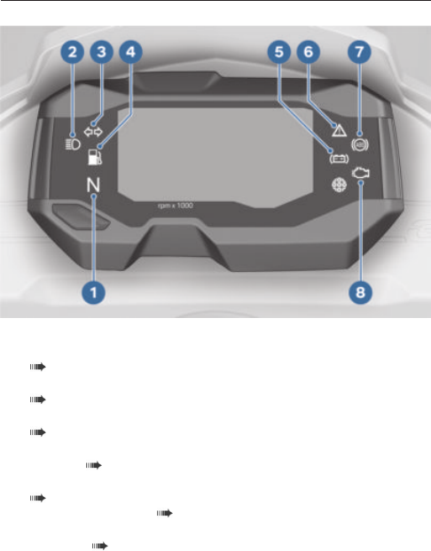
22 STATUS INDICATORS
WARNING AND INDICATOR LIGHTS
1 Neutral indicator light
2 High beam indicator light
( 36)
3 Turn signal indicator light
( 37)
4 Fuel reserve indicator light
( 29)
5 Warning light for vehicle
voltage ( 26)
6 General warning light
( 24)
7 ABS warning light ( 28)
8 Warning light, drive mal-
function ( 27)


24 STATUS INDICATORS
WARNING INDICATORS
Mode of presentation
Warnings are indicated by the
corresponding warning lights.
If two or more warnings occur
at the same time, all the ap-
propriate warning lights and
warning symbols appear.
The possible warnings are lis-
ted on the next pages.
Warnings that do not have
warning lights of their own are
indicated by a warning sym-
bol 1 appearing in the multi-
function display in combination
with 'General' warning light 2.
Depending on how urgent the
warning is, the general warning
light will either light up or flash
red or yellow.

25
Warnings, overview
Indicator and
warning lights
Display text Meaning
lights up. Vehicle voltage is
too low ( 26)
flashes red.
is displayed.
Coolant tempe-
rature too high
( 26)
lights up
yellow.
is displayed. Engine in emer-
gency-operation
mode ( 26)
lights up
yellow.
flashes.
Engine warning
( 27)
lights up.
Drive malfunction
( 27)
lights up
yellow.
flashes. Serious drive mal-
function ( 28)
flashes.
flashes. ABS self-dia-
gnosis not com-
pleted ( 28)
lights up.
ABS fault ( 28)
lights up. Fuel down to re-
serve ( 29)
lights up
yellow.
SERVICE is dis-
played constantly.
Service appoint-
ment has passed
( 29)

26 STATUS INDICATORS
Vehicle voltage is too low
lights up.
WARNING
Failure of the vehicle sys-
tems
Risk of accident
Do not continue your jour-
ney.
Possible cause:
Battery is faulty.
Have the fault rectified as
quickly as possible by a spe-
cialist workshop, preferably
an authorised BMW Motorrad
dealer.
Coolant temperature too high
flashes red.
is displayed.
ATTENTION
Riding with overheated en-
gine
Engine damage
Compliance with the inform-
ation set out below is essen-
tial.
Possible cause:
The coolant level is too low.
Check the coolant level
( 82).
If the coolant level is too low:
Top up the coolant ( 83).
Possible cause:
The radiator is dirty.
Clean radiator ( 118).
Possible cause:
The fan or fan control is faulty.
Have the fault rectified as
quickly as possible by a spe-
cialist workshop, preferably
an authorised BMW Motorrad
dealer.
Possible cause:
The coolant circuit is faulty.
If possible, allow the engine
to cool down.
Only ride in partial load range.
If the coolant temperature
is often too high, have the
fault rectified as soon as pos-
sible by a specialist work-
shop, preferably an authorised
BMW Motorrad dealer.
Engine in emergency-
operation mode
lights up yellow.
is displayed.

27
WARNING
Unusual ride characterist-
ics when engine running in
emergency-operation mode
Risk of accident
Avoid accelerating sharply
and overtaking.
Possible cause:
The engine control unit has
diagnosed a fault which im-
pairs the engine performance
or throttle response. The en-
gine is in emergency-operation
mode. In exceptional cases, the
engine stops and refuses to
start.
Have the fault rectified as
quickly as possible by a spe-
cialist workshop, preferably
an authorised BMW Motorrad
dealer.
It is possible to continue rid-
ing, however the engine per-
formance and engine speed
range may be impaired and
not function as normal.
Engine warning
lights up yellow.
flashes.
WARNING
Engine damage when run-
ning in emergency-operation
mode
Risk of accident
Ride slowly, avoid accelerat-
ing sharply and overtaking.
If possible, have the vehicle
picked up and have the
fault rectified by a specialist
workshop, preferably an
authorised BMW Motorrad
Retailer.
Possible cause:
The engine control unit has
diagnosed a fault which may
cause severe secondary faults.
The engine is in emergency-op-
eration mode.
Avoid high load and rpm
ranges if possible.
Have the fault rectified as
quickly as possible by a spe-
cialist workshop, preferably
an authorised BMW Motorrad
dealer.
It is possible to continue to
ride but not recommended.
Drive malfunction
lights up.

28 STATUS INDICATORS
Possible cause:
The engine control unit has
diagnosed a fault that affects
pollutant emissions and/or re-
duces power.
Have the fault rectified
by a specialist workshop,
preferably an authorised
BMW Motorrad retailer.
You can continue riding; pol-
lutant emissions are higher
than the threshold values.
Serious drive malfunction
lights up yellow.
flashes.
flashes.
Possible cause:
The engine control unit has dia-
gnosed a fault that can lead to
damage to the exhaust system.
Have the fault rectified as
quickly as possible by a spe-
cialist workshop, preferably an
authorised BMW Motorrad re-
tailer.
It is possible to continue to
ride but not recommended.
ABS self-diagnosis not
completed
flashes.
Possible cause:
ABS self-diagnosis not
completed
The ABS function is not
available, because self-
diagnosis did not complete.
(The motorcycle has to reach
a defined minimum speed
for the wheel sensors to be
checked: min 5 km/h)
Pull away slowly. Bear in
mind that the ABS function
is not available until self-
diagnosis has completed.
ABS fault
lights up.
Possible cause:
The ABS control unit has de-
tected a fault. The ABS func-
tion is not available or the func-
tionality is subject to certain
restrictions.
You can continue to ride the
vehicle, but make due pro-
vision for the fact that the
ABS function is not avail-
able or is only conditionally
available. Please refer to the
more detailed information on
situations that may lead to an
ABS fault ( 67).
Have the fault rectified as
quickly as possible by a spe-
cialist workshop, preferably

29
an authorised BMW Motorrad
dealer.
Fuel down to reserve
lights up.
WARNING
Irregular engine operation or
engine shutdown due to lack
of fuel
Risk of accident, damage to
catalytic converter
Do not run the fuel tank dry.
Possible cause:
The fuel has all been used up;
only the fuel reserve remains.
Fuel reserve
approx. 1 l
Refuelling ( 59).
Service appointment has
passed
lights up yellow.
SERVICE is displayed con-
stantly.
Possible cause:
The driving performance or the
date indicate that servicing is
due.
Have your motorcycle ser-
viced regularly by a special-
ist workshop, preferably an
authorised BMW Motorrad
dealer.
The motorcycle remains op-
erationally safe and is suitably
road-safe.
The value of the motorcycle
is preserved to the greatest
possible extent.
SERVICE DISPLAY
Remaining distance until
service is due and service due
date
When a service is due
within 1000 km, the word
SERVICE 1 and countdown
distance 2 are displayed and
the distance counts down
in steps of 100 km. This
information appears briefly
after the Pre-Ride-Check
completes.

30 STATUS INDICATORS
When the next service is due
within a month, the word
SERVICE 1 and service due
date 3 are displayed.
When the next service is due
on account of both the distance
covered and the service due
date, the word SERVICE 1,
countdown distance 2 and
service due date 3 are dis-
played.
SERVICE displayed constantly
If the service due date has
passed or the service distance
is exceeded, SERVICE 1 is
displayed constantly whenever
the vehicle is in use.
FUEL RESERVE
Range
Range readout RANGE 1 in-
dicates how far you can ride 2
with the fuel remaining in the
tank. This distance is calculated
on the basis of average con-
sumption and the quantity of
fuel on board.

31
When the motorcycle is
propped on its side stand
the slight angle of inclination
means that the sensor
cannot register the fuel level
correctly. This is the reason
why the range is recalculated
only when the side stand is in
the retracted position.
The range reading appears
automatically on the multi-
function display when fuel is
down to the reserve level.
After a refuelling stop, range
is recalculated if the amount
of fuel in the tank is greater
than the reserve quantity.
The calculated range is only
an approximate figure.
REV. COUNTER
1 Unit for engine speed
display:
1000 revolutions per
minute
2 Low engine speed range
3 Engine speed display seg-
ments
4 High engine speed range
5 rpm redline warning
( 56).

OPERATION
04


34 OPERATION
IGNITION
Keys
You receive 2 vehicle keys.
Ignition switch/steering lock,
fuel filler cap lock and seat lock
are all operated with the same
key.
Engaging steering lock
ATTENTION
Handlebars turned in wrong
direction when motorcycle
propped on side stand
Risk of damage to parts if
vehicle topples
On level ground, always turn
the handlebars to the left to
set the steering lock.
In all other cases it is the lie
of the ground that determ-
ines the direction in which
the handlebars should be
turned.
If the camber of the roadway
permits, turn the handlebars
all the way to the left.
Push the ignition key 1 into
the steering lock and turn to
the LOCK position, moving
the handlebars slightly as you
do this.
Ignition, lights and all function
circuits are switched off.
Handlebars are locked.
Vehicle key can be removed.
Switching on ignition
Insert the ignition key 1 into
the ignition steering lock and
turn it to the ON position.
Side lights, low-beam head-
light and all function circuits
are switched on.
Engine can be started.

35
Pre-Ride-Check is performed.
( 54)
ABS self-diagnosis is per-
formed ( 55)
Switching off ignition
Turn the ignition key 1 to
the OFF position.
Handlebars (steering lock) are
not locked.
Vehicle key can be removed.
Emergency-off switch (kill
switch)
A = Operation mode
B = Emergency-off (en-
gine is switched off)
Emergency-off or operation
mode
WARNING
Operation of the kill switch
while riding
Risk of fall due to rear wheel
locking
Do not operate the kill
switch when riding.
Push emergency-off switch 1
forward as the easiest way of
killing the engine.
Push emergency-off switch 1
back so that the engine can
be started.
LIGHTS
Low-beam headlight and
sidelights
The side lights switch on auto-
matically when the ignition is
switched on.
The low-beam headlight
and the side light drain
the battery. Do not switch the

36 OPERATION
ignition on for longer than ab-
solutely necessary.
The low-beam headlight
switches on automatically
under the following conditions:
When the engine is started.
If the vehicle is pushed while
the ignition is on.
When the engine is not
running you can switch on
the lights by switching on the
ignition and either switching
on the high-beam headlight or
operating the headlight flasher.
with daytime riding light
OE
In daytime the daytime riding
light can be switched on as an
alternative to the low-beam
headlight.
High-beam headlight,
operating
Push switch 1 forward.
The high beam is switched
on.
High beam indicator light
lights up.
Move switch 1 to the centre
position.
The blue high beam indicator
light goes out.
The low-beam headlight is
switched on.
Using daytime riding light
with daytime riding light
OE
WARNING
Switching on the daytime
riding light in the dark.
Risk of accident
Do not use the daytime rid-
ing light in the dark.
By comparison with the
low-beam headlight, the
daytime running light makes
the vehicle more visible to on-
coming traffic. This improves
daytime visibility.
Push switch 1 back.

37
Daytime riding light is
switched on.
Move switch 1 to the centre
position.
The low-beam headlight is
switched on.
Headlight flasher, operating
Press button 1.
The high-beam headlight is
switched on until you release
the button.
TURN INDICATORS
Operating the turn indicators
Switch on the ignition ( 34).
Push switch 1 to the left.
The left turn indicator is
switched on.
The turn indicator telltale
light flashes.
Push switch 1 to the right.
The right turn indicator is
switched on.
The turn indicator telltale
light flashes.
Centre switch 1 to cancel the
turn indicators.

38 OPERATION
MULTIFUNCTION DISPLAY
Selecting display
Requirement
The vehicle is at a standstill.
Switch on the ignition.
The on-board computer read-
ings appear on the display.
Repeatedly short-press but-
ton 1 until the desired value is
displayed.
Possible displays:
Total distance travelled: ODO
Trip distance 1: TRIP1
Trip distance 2: TRIP2
Coolant temperature: ENGIN
Range: RANGE
Average fuel consumption:
CONS1
Current fuel consumption:
CONSA
Average speed: SPEED
Date: DATE
Settings: SETUP

39
DATE AND TIME
Setting clock
Select the display ( 38).
SETUP 2 is displayed.
Long-press button 1.
Hours number 3 flashes.
Press button 1 briefly to in-
crease the hour 3.
Press and hold button 1 once
the desired hour has been set.
Minutes number 4 flashes.
Press button 1 briefly to in-
crease the minutes.
Press and hold button 1 once
the desired minute has been
set.
The time has not yet been
saved.
Set the date ( 39).
Setting date
Requirement
The clock has been set.
Press button 1 briefly to in-
crease the date 7.
Press and hold button 1 once
the desired date has been set.
Month 6 flashes.
Press button 1 briefly to in-
crease the month 6.
Press and hold button 1 once
the desired month has been
set.
Year 5 flashes.
Press button 1 briefly to in-
crease the year.
Press and hold button 1 once
the desired year has been set.
The time and date settings
have been saved.
RESETTING TRIP DISTANCE
Select the display ( 38).
The trip distance 2 to be re-
set has been selected.
TRIP1 or TRIP2 appears on
the display.

40 OPERATION
Press button 1 and hold it
down until value 3 is reset.
RESETTING THE AVERAGE
VALUES
Select the display ( 38).
The average value 2 to be re-
set has been selected.
CONSI or SPEED appears on
the display.
Press button 1 and hold it
down until value 3 is reset.
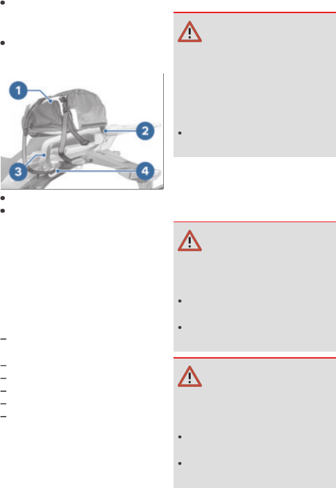
SEAT
Removing seat
Make sure the ground is level
and firm and place the motor-
cycle on its stand.
Press down on the rear part
of seat 2 to relieve the strain
on the lock and at the same
time unlock the seat lock by
turning ignition key 1 clock-
wise.
Lift the seat at the rear and
remove.
Lay the seat on a clean sur-
face.

41
Installing seat
Engage seat 1 with mount 3
centred in battery tray 4.
Position detent pin 2 and
push it into the lock.

ADJUSTMENT
05


44 ADJUSTMENT
MIRRORS
Adjusting mirrors
Turn the mirror to the desired
position.
Adjusting mirror arm
Push protective cap 1 up the
mirror arm to expose the
threaded fastener.
Loosen lock nut 2.
Turn the mirror arm to the
appropriate position.
Tighten the locknut to the
specified tightening torque,
while holding the mirror arm
to ensure that it does not
move out of position.
Right mirror (lock nut)
to adapter
22 Nm (Left-hand thread)
Left mirror (lock nut) to
adapter
22 Nm
Push protective cap 1 over
the threaded fastener.
HEADLIGHT
Adjusting headlight for
driving on left/driving on right
This motorcycle has a symmet-
ric-beam low-beam headlight.
If the motorcycle is ridden in
a country where the oppos-
ite rule of the road applies, its
symmetric low-beam headlight
means that no measures are
necessary to prevent the head-
light beam from dazzling on-
coming traffic.
Headlight beam throw and
spring preload
Headlight beam throw is
generally kept constant when
spring preload is adjusted to
suit load. Headlight beam
throw is set correctly ex-works.
If there are doubts about
the correct headlight
beam throw, have the setting
checked by a specialist work-

45
shop, preferably an authorised
BMW Motorrad dealer.
Adjusting headlight beam
throw
Requirement
Even with spring preload
correctly adjusted, oncoming
traffic is dazzled if the motor-
cycle is heavily loaded.
Loosen bolt 1.
Swivel the headlight to adjust
beam throw.
Tighten screw 1 while holding
the headlight so that it cannot
move out of position.
When the motorcycle is again
ridden with a lower load:
Have the basic settings of the
headlight restored by a spe-
cialist workshop, best of all by
a BMW Motorrad dealer.
SPRING PRELOAD
Adjustment
Spring preload has to be ad-
justed to suit the weight of
rider, passenger and luggage.
Increase spring preload for
heavier riders, decrease spring
preload for lighter riders.
Adjusting spring preload for
rear wheel
Make sure the ground is level
and firm and place the motor-
cycle on its stand.
Remove screw 2.
Pull frame panel 3 out of the
grommets and remove it.

46 ADJUSTMENT
To increase spring preload,
use the appropriate tool from
the on-board toolkit to turn
adjusting ring 1 in arrow dir-
ection A.
To reduce spring preload, use
the appropriate tool from the
on-board toolkit to turn ad-
justing ring 1 in arrow direc-
tion B.
Basic setting of spring
preload, rear
Stage 1 (One-up riding
without luggage)
Stage 5 (One-up with lug-
gage)
Stage 10 (Two-up and with
luggage)
Engage frame panel 3 in
grommets 4.
Align frame panel 3 with flat
nut 5.
Install frame panel 3 with
screw 2.
BRAKES
Adjusting handbrake lever
WARNING
Relocated brake fluid tank
Air in the brake system
Do not turn the handlebars
or the handlebar fitting on
the handlebar.

47
WARNING
Adjusting the handbrake
lever while riding
Risk of accident
Do not attempt to adjust the
handbrake lever unless the
motorcycle is at a standstill.
Applying light pressure from
behind, turn adjusting screw 1
to the desired position.
The adjusting screw is
easier to turn when the
handbrake lever is pushed for-
ward.
Adjustment options:
From position 1: narrowest
span between handlebar grip
and handbrake lever
To position 4: widest span
between handlebar grip and
handbrake lever
CLUTCH
Adjusting clutch lever
WARNING
Adjusting the clutch lever
while riding
Risk of accident
Adjust the clutch lever only
when the motorcycle is at a
standstill.
Applying light pressure from
behind, turn adjusting screw 1
to the desired position.
The adjusting screw can
be turned more easily if
the clutch lever is pushed for-
ward.
Adjustment options:
From position 1: narrowest
span between handlebar grip
and clutch lever
To position 4: widest span
between handlebar grip and
clutch lever

RIDING
06


50 RIDING
SAFETY INSTRUCTIONS
Rider's equipment
Do not ride without the correct
clothing! Always wear
Helmet
Suit
Gloves
Boots
This applies even to short
journeys, and to every season
of the year. Your authorised
BMW Motorrad retailer will
be happy to advise you on
the correct clothing for every
purpose.
WARNING
Loose textiles, items of lug-
gage or straps snagged by
open rotating parts of the
vehicle (wheels, drive shaft)
Risk of accident
Make sure that loosely worn
or carried textiles cannot be
snagged by openly rotating
parts of the vehicle.
Keep all items of luggage
and straps well clear of
openly rotating parts of the
vehicle.
Loading
WARNING
Handling adversely affected
by overloading and imbal-
anced loads
Risk of falling
Do not exceed the permiss-
ible gross weight and be
sure to comply with the in-
structions on loading.
Set spring preload to suit total
weight.
with topcase
OA
Note the maximum permiss-
ible payload and maximum
permissible speed, see
also the section entitled
"Accessories" ( 109).
Payload of topcase
max 5 kg
with topcase Light
OA
Note the maximum permiss-
ible payload and maximum
permissible speed, see
also the section entitled
"Accessories" ( 111).
Payload of topcase
max 3 kg
51
Make sure that the weight is
uniformly distributed between
right and left.
Stow heavy items at the bot-
tom.
Lash luggage 1 securely.
Pass retaining straps 2
through eyes 4 of luggage
carrier 3 and tighten.
Speed
If you ride at high speed, al-
ways bear in mind that various
boundary conditions can ad-
versely affect the handling of
your motorcycle:
Incorrect adjustment of the
spring system
Imbalanced load
Loose clothing
Insufficient tyre pressure
Poor tyre tread
Etc.
Top speed
DANGER
Maximum speed of the mo-
torcycle is higher than the
permissible maximum rated
speed of the tyres
Risk of accident due to tyre
damage at high speed
Comply with the tyre-spe-
cific speed restrictions.
Risk of poisoning
Exhaust fumes contain carbon
monoxide, which is colourless
and odourless but highly toxic.
WARNING
Exhaust gases adversely af-
fecting health
Risk of asphyxiation
Do not inhale exhaust
fumes.
Do not run the engine in an
enclosed space.
WARNING
Inhalation of harmful va-
pours
Health hazard
Do not inhale vapours from
operating fluid and plastics.
Use the vehicle only out-
doors.

52 RIDING
Risk of burn injury
CAUTION
Engine and exhaust system
become very hot when the
vehicle is in use
Risk of burn injury
When you park the vehicle
make sure that no-one and
no objects can come into
contact with the hot engine
and exhaust system.
Catalytic converter
If misfiring causes unburned
fuel to enter the catalytic con-
verter, there is a danger of
overheating and damage.
For this reason, observe the
following points:
Do not run the fuel tank dry.
Do not remove the spark plug
connector while the engine is
running.
Stop the engine immediately
if it misfires.
Use only unleaded fuel.
Comply with all specified
maintenance intervals.
ATTENTION
Unburned fuel in catalytic
converter
Damage to catalytic converter
Note the points listed for
protection of the catalytic
converter.
Risk of overheating
ATTENTION
Engine running for pro-
longed period with vehicle
at standstill
Overheating due to insuf-
ficient cooling; in extreme
cases vehicle fire
Do not allow the engine to
idle unnecessarily.
Ride away immediately after
starting the engine.

53
Tampering
ATTENTION
Tampering with the motor-
cycle (e.g. engine manage-
ment ECU, throttle valves,
clutch)
Damage to the affected parts,
failure of safety-relevant func-
tions, voiding of warranty
Do not tamper with the
vehicle in any way that could
result in tuned performance.
REGULAR CHECK
Comply with checklist
At regular intervals, use the
checklist below to check your
motorcycle.
Always before riding off
Checking function of brakes
( 76).
Check that the lights and sig-
nalling equipment function.
Checking clutch function
( 81).
Checking tyre tread depth
( 84).
Checking tyre pressure
( 83).
Check that the luggage is se-
cure.
Every 3rd refuelling stop
Check the engine oil level
( 74).
Check the brake pad thick-
ness, front brakes ( 76).
Check the brake pad thick-
ness, rear brakes ( 77).
Check the brake-fluid level,
front brakes ( 78).
Check the brake-fluid level,
rear brakes ( 79).
Check the coolant level
( 82).
Lubricating chain ( 94).
Check the chain tension
( 94).
STARTING
Starting engine
Switch on the ignition.
Pre-Ride-Check is performed.
( 54)
ABS self-diagnosis is per-
formed ( 55)
Select neutral.
Idle mode indicator light
lights up.
Idle mode appears on the
display.
Alternatively: with the trans-
mission in gear, pull the clutch
lever.
You cannot start the mo-
torcycle with the side
stand extended and a gear en-
gaged. The engine will switch

54 RIDING
itself off if you start it with the
gearbox in neutral and then en-
gage a gear before retracting
the side stand.
Keep throttle grip closed
or turn it only slightly.
For a cold engine start and
low temperatures: pull clutch.
Set the emergency-off
switch 1 to Operation.
Switch is in operation
mode.
Press the starter button 2.
The engine starts.
Consult the troubleshooting
chart below if the engine re-
fuses to start. ( 124)
Pre-Ride-Check
The instrument cluster runs
a test of the warning and in-
dicator lights and the display
when the ignition is switched
on. This test is known as the
Pre-Ride-Check. The check is
aborted if you start the engine
before it completes.
Phase 1
"General" warning light 1 lights
up red.
The indicator lights 5 light up.
Display 4 shows the most re-
cently active information con-
figuration.
The rpm redline warning 3
lights up.
The warning lights 2 light up.
Phase 2
'General' warning light 1
changes from red to yellow.
Phase 3
The indicator and warning
lights and the rpm redline
warning go out or assume op-
erational status, as applicable.
The malfunction indicator lamp
(MIL) does not go out until
15 seconds have elapsed.

55
If a service is due, the relevant
information is briefly displayed.
If one of the warning or indic-
ator lights does not show:
WARNING
Faulty warning lights
No indication of malfunctions
Check all the telltale and
warning lights.
Have the fault rectified as
quickly as possible by a spe-
cialist workshop, preferably an
authorised BMW Motorrad re-
tailer.
ABS self-diagnosis
BMW Motorrad ABS performs
self-diagnosis to ensure its op-
erability. Self-diagnosis starts
automatically when you switch
on the ignition.
Phase 1
Test of the diagnosis-compat-
ible system components with
the vehicle at a standstill.
flashes.
Phase 2
Test of the wheel-speed
sensors as the vehicle pulls
away from rest.
flashes.
ABS self-diagnosis completed
The ABS indicator and warn-
ing light goes out.
ABS self-diagnosis not
completed
The ABS function is not
available, because self-
diagnosis did not complete.
(The motorcycle has to reach
a defined minimum speed
for the wheel sensors to be
checked: min 5 km/h)
If an indicator showing an ABS
fault appears when ABS self-
diagnosis completes:
You can continue to ride.
Bear in mind that the ABS
function is not available.
Have the fault rectified as
quickly as possible by a spe-
cialist workshop, preferably
an authorised BMW Motorrad
Retailer.
RUNNING IN
Engine
Until the running-in check,
vary the throttle opening
and engine-speed range
frequently; avoid riding at
constant engine rpm for
prolonged periods.

56 RIDING
Try to do most of your riding
during this initial period on
twisting, fairly hilly roads.
Comply with the rpm limits
for running in.
Running-in speed
<6000 min
-1
(Odometer
reading 0...300 km)
No full load (Odometer read-
ing 0...1000 km)
Note the mileage after which
the running-in check should
be carried out.
Mileage until the run-
ning-in check
500...1200 km
Brake pads
New brake pads have to bed-
ded in before they can achieve
their optimum frictional force.
You can compensate for this
initial reduction in braking effi-
ciency by exerting greater pres-
sure on the levers.
WARNING
New brake pads
Longer stopping distance, risk
of accident
Apply the brakes in good
time.
Tyres
New tyres have a smooth
surface. This must be
roughened by riding in a
restrained manner at various
heel angles until the tyres are
run in. Only once the surface
has been roughened can the
tyres achieve maximum grip.
WARNING
New tyres losing grip on wet
roads and at extreme bank
angles
Risk of accident
Ride carefully and avoid ex-
tremely sharp inclines.
RPM REDLINE WARNING
Requirement
Vehicle not yet in 6th gear,
maximum acceleration
required.
Accelerate.

57
The rpm redline warn-
ing 1 lights up when
the following engine speed is
reached:
>10000 min
-1
Take care not to exceed the
following engine speed:
Maximum engine speed
max 10800 min
-1
Upshift to the next gear.
BRAKES
How can stopping distance be
minimised?
Each time the brakes are ap-
plied, a load distribution shift
takes place with the load shift-
ing forward from the rear to
the front wheel. The sharper
the motorcycle decelerates,
the more load is shifted to the
front wheel. The higher the
wheel load, the more brak-
ing force can be transmitted
without the wheel locking.
In order to achieve the shortest
stopping distance, the front
wheel brake must be pulled
quickly until ABS activates, the
pressure point held and the
rear wheel brake operated at
the same time. This makes
the best possible use of the
dynamic increase in load at the
front wheel. Remember to pull
the clutch at the same time.
BMW Motorrad ABS prevents
the front wheel from locking.
In the "emergency braking situ-
ations" that are trained so fre-
quently, braking force is ap-
plied as rapidly as possible and
with the rider's full force ap-
plied to the brake levers; un-
der these circumstances the
dynamic shift in load distribu-
tion cannot keep pace with the
increase in deceleration and
the tyres cannot transmit the
full braking force to the surface
of the road. In the absence
of load on the wheel the ABS
has to intervene to prevent the
front wheel from locking even
if the brakes are applied only
very lightly. This leads to a re-
duced braking effect.
Descending mountain passes
WARNING
Braking mostly with the rear
brake on mountain descents
Brake fade, destruction of the
brakes due to overheating
Use both front and rear
brakes, and make use of the
engine's braking effect as
well.

58 RIDING
Wet and dirty brakes
Wetness and dirt on the brake
discs and the brake pads di-
minish braking efficiency.
Delayed braking action or poor
braking efficiency must be
reckoned with in the follow-
ing situations:
Riding in the rain or through
puddles of water
After the vehicle has been
washed
Riding on salted or gritted
roads
After work has been carried
on the brakes, due to traces
of oil or grease
Riding on dirt-covered sur-
faces or off-road
WARNING
Wetness and dirt result in
diminished braking effi-
ciency
Risk of accident
Apply the brakes lightly
while riding to remove
wetness and dirt, or
dismount and clean the
brakes.
Think ahead and brake in
good time until full braking
efficiency is restored.
PARKING YOUR
MOTORCYCLE
Side stand
Switch off the engine.
On a gradient, the motorcycle
should always face uphill; se-
lect 1st gear.
ATTENTION
Poor ground underneath the
stand
Risk of damage to parts if
vehicle topples
Always check that the
ground under the stand is
level and firm.
Extend the side stand and
prop the motorcycle on the
stand.
ATTENTION
Additional weight placing
strain on the side stand
Risk of damage to parts if
vehicle topples
Do not sit or lean on the
vehicle while it is propped
on the side stand.
If the camber of the roadway
permits, turn the handlebars
all the way to the left.

59
REFUELLING
Fuel grade
Requirement
For optimum fuel consumption,
fuel has to be sulphur-free or
with the lowest sulphur content
possible.
ATTENTION
Engine operation with
leaded fuel
Damage to catalytic converter
Do not attempt to run the
vehicle on leaded fuel or fuel
with metallic additives (e.g.
manganese or iron).
ATTENTION
Engine operation with eth-
anol E85
Damage to engine and fuel
supply system
Do not attempt to run the
engine on ethanol E85, i.e. a
fuel with an ethanol content
of 85 %, or flex fuel.
Note fuel grade.
Fuel additives clean the
fuel injection system and
the combustion zone. It is ad-
visable to use fuel additives
when the engine is operated
with low-grade fuel or if the
vehicle is to be out of use for
a lengthy period of time. More
information is available from
your authorised BMW Motorrad
retailer.
Recommended fuel
grade
Regular unleaded (max-
imum 15 % ethanol,
E15)
91 ROZ/RON
87 AKI
Pay attention to the following
symbols in the fuel filler cap
and on the fuel pump:
Refuelling
WARNING
Fuel is highly flammable
Risk of fire and explosion
Do not smoke. Never bring
a naked flame near the fuel
tank.
60 RIDING
ATTENTION
Component damage
Component damage caused
by overfilled fuel tank
Overfilling the fuel tank will
cause excess fuel to penet-
rate the carbon canister and
cause component damage.
Fill the fuel tank up to the
lower edge of the filler neck
only.
ATTENTION
Wetting of plastic surfaces
by fuel
Damage to the surfaces (sur-
faces become unsightly or
dull)
Clean plastic surfaces im-
mediately after contact with
fuel.
Make sure the ground is level
and firm and place the motor-
cycle on its side stand.
Open the protective cap 2.
Unlock the cap of the fuel
tank by turning ignition key 1
clockwise in the lock and pop
the cap open.
Refuel with fuel of the grade
stated above; do not fill the
tank past the bottom edge of
filler neck 3. When refuelling
be aware of the divider in the
fuel filler neck and take care,
so that fuel cannot escape.
When refuelling after run-
ning on reserve, make
sure that you top up the tank
to a level above reserve, so that
the new level is detected and

61
the fuel reserve indicator light
is switched off.
The "usable fuel capacity"
specified in the technical
data is the quantity that the
fuel tank could hold if refilled
after it had been run dry and
the engine had cut out due to a
lack of fuel.
Usable fuel capacity
approx. 11.5 l
Fuel reserve
approx. 1 l
Unlock the cap of the fuel
tank by turning ignition key 1
clockwise in the lock and
press the cap down firmly to
close.
Remove the ignition key and
close the protective cap.
SECURING MOTORCYCLE
FOR TRANSPORTATION
Make sure that all compon-
ents that might come into
contact with straps used to
secure the motorcycle are ad-
equately protected against
scratching. Use adhesive tape
or soft cloths, for example, for
this purpose.
ATTENTION
Vehicle topples to side when
being lifted on to stand
Risk of damage to parts if
vehicle topples
Secure the vehicle to pre-
vent it toppling, preferably
with the assistance of a
second person.
Push the motorcycle onto the
transportation flat and hold it
in position: do not place it on
the side stand.

62 RIDING
ATTENTION
Trapping of components
Component damage
Do not trap components
such as brake lines or cable
legs.
At the front, loop a strap over
the bottom fork bridge on
each side.
Pull the straps down and
tight.
Secure the rear tensioning
straps on both sides on the
holders for the rear footrests
and tension them.
Uniformly tighten all the
straps.
The vehicle's springs are com-
pressed.
63

ENGINEERING
DETAILS
07


66 ENGINEERING DETAILS
GENERAL INSTRUCTIONS
To find out more on the sub-
ject of engineering go to:
bmw-motorrad.com/technik
ANTILOCK BRAKING SYSTEM
How does ABS work?
The amount of braking force
that can be transferred to the
road depends on factors that
include the coefficient of fric-
tion of the road surface. Loose
stones, ice and snow or a wet
road all have much lower coef-
ficients of friction than a clean,
dry asphalt surface. The lower
the coefficient of friction, the
longer the braking distance.
If the rider increases braking
pressure to the extent that
braking force exceeds the max-
imum transferable limit, the
wheels start to lock and the
motorcycle loses its directional
stability. A fall is imminent. Be-
fore this situation can occur,
ABS intervenes and adapts
brake pressure to the max-
imum transferable brake force,
so the wheels continue to turn
and driving stability is main-
tained irrespective of the con-
dition of the road surface.
What are the effects of
surface irregularities?
Humps and surface irregular-
ities can cause the wheels to
lose contact temporarily with
the road surface; if this hap-
pens the braking force that
can be transmitted to the road
can drop to zero. If the brakes
are applied under these cir-
cumstances the ABS has to
reduce braking force to en-
sure that directional stability
is maintained when the wheels
regain contact with the road
surface. At this instant the ABS
must assume an extremely low
coefficient of friction, so that
the wheels will continue to ro-
tate under all imaginable cir-
cumstances, because this is
the precondition for ensuring
directional stability. As soon
as is registers the actual cir-
cumstances, the system reacts
instantly and adjusts braking
force accordingly to achieve
optimum braking.
Rear wheel lift
Even under severe braking, a
high level of tyre grip can mean
that the front wheel does not
lock up until very late, if at all.
Consequently, ABS does not
intervene until very late, if at
all. Under these circumstances

67
the rear wheel can lift off the
ground, and the outcome can
be a highsiding situation in
which the motorcycle can flip
over.
WARNING
Rear wheel lift due to severe
braking
Risk of falling
When you brake sharply,
bear in mind that ABS con-
trol cannot always be re-
lied on to prevent the rear
wheel from lifting clear of
the ground.
What is the design baseline
for BMW Motorrad ABS?
Within the limits im-
posed by physics, the
BMW Motorrad ABS ensures
directional stability on any
surface.
At speeds above 4 km/h,
within the limits im-
posed by physics the
BMW Motorrad ABS can
ensure directional stability
on any surface. Limitations
inherent to the design principle
mean that at lower speeds the
BMW Motorrad ABS cannot
provide optimum assistance on
all surfaces.
The system is not optimised
for special requirements that
apply under extreme competit-
ive situations off-road or on the
track.
Special situations
The speeds of the front and
rear wheels are compared
as one means of detecting a
wheel's incipient tendency to
lock. If the system registers
implausible values for a lengthy
period the ABS function is
deactivated for safety reasons
and an ABS fault message
is issued. Self-diagnosis has
to complete before fault
messages can be issued.
In addition to problems with
the BMW Motorrad ABS, ex-
ceptional riding conditions can
lead to a fault message being
issued.
If a fault message should be
triggered due to one of the
above-described driving condi-
tions, the ABS function can be
re-activated by switching the
ignition off and then on again.
Exceptional riding conditions:
Heating up with the motor-
cycle on an auxiliary stand,
in neutral or with a gear en-
gaged.

68 ENGINEERING DETAILS
Rear wheel locked by the
engine brake for a lengthy
period, for example while des-
cending steep gradients.
What significance devolves on
regular maintenance?
WARNING
Brake system not regularly
serviced
Risk of accident
In order to ensure that
the BMW Motorrad ABS
is always maintained in
optimum condition, it is
essential for you to comply
strictly with the specified
inspection intervals.
Safety reserves
The potentially shorter
braking distances which
BMW Motorrad ABS permits
must not be used as an
excuse for careless riding. The
system is primarily a means
of ensuring a safety margin in
genuine emergencies.
WARNING
Braking when cornering
Risk of accident despite ABS
Invariably, the rider bears
responsibility for assessing
road and traffic conditions
and adopting his or her style
of riding accordingly.
Do not take risks that would
negate the additional margin
of safety offered by this sys-
tem.
69

MAINTENANCE
08


72 MAINTENANCE
GENERAL NOTES
The Maintenance chapter de-
scribes straightforward proced-
ures for checking and replacing
certain wear parts.
Special tightening torques are
listed as applicable. The tight-
ening torques for the threaded
fasteners on your motorcycle
are listed in the section entitled
"Technical data".
Further information on main-
tenance and repair work is
available from your authorised
BMW Motorrad retailer in the
form of a DVD.
Some of the work requires
special tools and a thorough
knowledge of the technology
involved. If you are in doubt,
consult a specialist workshop,
preferably your authorised
BMW Motorrad retailer.
TOOLKIT
1 Open-ended spanner
Width across flats 12/13
Adjust the chain tension
( 93).
2 Open-ended spanner
Width across flats 10/16
Adjust the mirror arm
( 44).
Remove the battery
( 99).
3 Hook wrench
Adjust the spring
preload for rear wheel
( 45).
4 Ring spanner
Width across flats 27
Remove the rear wheel
( 89).
Adjust the chain tension
( 93).
5 Extension for hook
wrench and ring spanner
6 Reversible screwdriver
blade with cross head
7 Screwdriver handle
8 Allen key
5 mm

73
8 Adjust headlight beam
throw ( 45).
9 Reserve fuses
Miniature fuses, 7.5 A and
15 A
There are spare fuses in
the fuse box.
FRONT-WHEEL STAND
Installing front-wheel stand
ATTENTION
Use of the BMW Motorrad
front-wheel stand without
accompanying use of centre
stand or auxiliary stand
Risk of damage to parts if
vehicle topples
Place the motorcycle on
its centre stand or another
auxiliary stand before lift-
ing the front wheel with the
BMW Motorrad front-wheel
stand.
Place the motorcycle
on an auxiliary stand;
BMW Motorrad recommends
the BMW Motorrad rear-
wheel stand.
Install the rear-wheel stand
( 73).
See the instructions issued
with the front-wheel stand
for the details of the correct
procedure for installation.
BMW Motorrad offers an aux-
iliary stand suitable for every
vehicle. Your BMW Motorrad
retailer will be happy to help
you with the selection of a
suitable auxiliary stand.
REAR-WHEEL STAND
Installing rear-wheel stand
The description of how to fit
the rear-wheel stand correctly
will be found in the instruc-
tions for the stand.
BMW Motorrad offers an aux-
iliary stand suitable for every

74 MAINTENANCE
vehicle. Your BMW Motorrad
retailer will be happy to help
you with the selection of a
suitable auxiliary stand.
ENGINE OIL
Checking engine oil level
ATTENTION
Misinterpretation of oil level
reading, because oil level is
temperature-dependent (the
higher the temperature, the
higher the oil level)
Engine damage
Check the oil level only after
a lengthy ride or when the
engine is at operating tem-
perature.
Place the motorcycle
on an auxiliary stand;
BMW Motorrad recommends
the BMW Motorrad auxiliary
stand.
Alternatively: Hold the motor-
cycle upright, preferably with
the assistance of another per-
son.
ATTENTION
Vehicle toppling sideways
Risk of damage to parts if
vehicle topples
Secure the vehicle, prefer-
ably with the assistance of
a second person, so that it
cannot topple sideways.
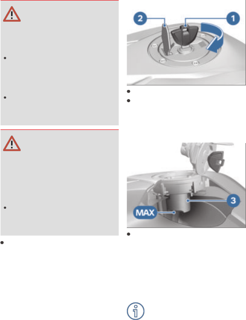
Check the oil level in the
display 1.

75
Engine oil, specified
level
Between MIN and MAX
marks (Engine is at operating
temperature, motorcycle is
upright)
Engine oil, quantity for
topping up
0.18 l (Difference between
MIN and MAX)
If the oil level is below the min-
imum mark MIN:
Top up the engine oil ( 75).
If the oil level is above the max-
imum mark MAX:
Have the oil level corrected
by a specialist workshop,
preferably an authorised
BMW Motorrad retailer.
To protect the environ-
ment, BMW Motorrad re-
commends occasionally check-
ing the engine oil after a jour-
ney of at least 50 km.
Topping up engine oil
Make sure the ground is level
and firm and place the motor-
cycle on its stand.
Wipe the area around the oil
filler opening clean.
Remove cap 1 of the oil filler
opening.
ATTENTION
Use of insufficient engine oil
or too much engine oil
Engine damage
Always make sure that the
oil level is correct.
Top up the engine oil to the
specified level.
Engine oil, quantity for
topping up
0.18 l (Difference between
MIN and MAX)
Check the engine oil level
( 74).
Install cap of oil filler open-
ing 1.

76 MAINTENANCE
BRAKE SYSTEM
Checking function of brakes
Operate the brake lever.
There is a clearly perceptible
pressure point.
Press the footbrake lever.
There is a clearly perceptible
pressure point.
If pressure points are not
clearly perceptible:
ATTENTION
Work on brake system not
in compliance with correct
procedure
Risk to operational reliability
of the brake system
Have all work on the
brake system undertaken
by trained and qualified
specialists.
Have the brakes checked
by a specialist workshop,
preferably an authorised
BMW Motorrad dealer.
Checking brake pad thickness,
front brakes
Make sure the ground is level
and firm and place the motor-
cycle on its stand.
Turn the handlebars all the
way to the right.
Looking from the rear, you
can see brake pads 1.
Visually inspect the brake
pads to ascertain their thick-
ness.
Note wear marks 2.
Brake-pad wear limit,
front
min 1.0 mm (Friction pad
only, without backing plate.
The wear indicators (grooves)
must be clearly visible.)

77
If the wear indicating marks are
no longer visible:
WARNING
Brake-pad thickness less
than permissible minimum
Diminished braking effect,
damage to the brakes
In order to ensure the de-
pendability of the brake
system, do not permit the
brake pads to wear past the
minimum permissible thick-
ness.
Have the brake pads replaced
by a specialist workshop,
preferably an authorised
BMW Motorrad retailer.
BMW Motorrad recommends
installing only genuine brake
pads from BMW Motorrad.
Checking brake pad thickness,
rear brakes
Make sure the ground is level
and firm and place the motor-
cycle on its stand.
Visually inspect the brake
pads to ascertain their thick-
ness. Viewing direction: from
the rear toward brake pads 1.
Note chamfer 2.

78 MAINTENANCE
Brake-pad wear limit,
rear
min 1.0 mm (Friction lining
without carrier plate. The
wear marks must be clearly
visible.)
If the chamfer is no longer vis-
ible:
WARNING
Brake-pad thickness less
than permissible minimum
Diminished braking effect,
damage to the brakes
In order to ensure the de-
pendability of the brake
system, do not permit the
brake pads to wear past the
minimum permissible thick-
ness.
Have the brake pads replaced
by a specialist workshop,
preferably an authorised
BMW Motorrad retailer.
Checking brake-fluid level,
front brakes
WARNING
Not enough brake fluid in
brake fluid reservoir, or con-
taminants in brake fluid
Considerably reduced braking
power due to presence of air,
contaminants or water in the
brake system
Cease operation of the
vehicle immediately and do
not ride it until the fault has
been rectified.
Check the brake-fluid levels
at regular intervals.
Always make sure that the
lid of the brake fluid reser-
voir and the area around the
lid are cleaned before open-
ing.
Make sure that only fresh
brake fluid from a sealed
container is used.
Make sure the ground is level
and firm and hold the motor-
cycle upright.

79
Turn the handlebars to a pos-
ition in which the brake fluid
reservoir is horizontal.
Check the brake fluid level in
inspection glass 1.
Wear of the brake pads
causes the brake fluid
level in the reservoir to sink.
Brake fluid level, front
Brake fluid, DOT4
It is not permissible for the
brake fluid level to be below
the MIN mark. (Brake fluid
reservoir horizontal)
If the brake fluid level drops
below the permitted level:
Have the fault rectified as
quickly as possible by a spe-
cialist workshop, preferably an
authorised BMW Motorrad re-
tailer.
Checking brake-fluid level,
rear brakes
Make sure the ground is level
and firm and hold the motor-
cycle upright.
Remove screw 1.
Pull frame panel 2 out of the
grommets and remove it.

80 MAINTENANCE
Check the brake fluid level in
brake fluid reservoir 3.
Wear of the brake pads
causes the brake fluid
level in the reservoir to sink.
Brake fluid level, rear
Brake fluid, DOT4
It is not permissible for the
brake fluid level to be below
the MIN mark. (Brake fluid
reservoir horizontal)
If the brake fluid level drops
below the permitted level:
WARNING
Not enough brake fluid in
brake fluid reservoir, or con-
taminants in brake fluid
Considerably reduced braking
power due to presence of air,
contaminants or water in the
brake system
Cease operation of the
vehicle immediately and do
not ride it until the fault has
been rectified.
Check the brake-fluid levels
at regular intervals.
Always make sure that the
lid of the brake fluid reser-
voir and the area around the
lid are cleaned before open-
ing.
Make sure that only fresh
brake fluid from a sealed
container is used.
Have the fault rectified as
quickly as possible by a spe-
cialist workshop, preferably an
authorised BMW Motorrad re-
tailer.

81
Engage frame panel 2 in
grommets 4.
Align frame panel 2 with flat
nut 5.
Install frame panel 2 with
screw 1.
CLUTCH
Checking clutch function
Pull the clutch lever.
The clutch must fully disen-
gage. Signs that the clutch is
fully disengaged:
Easy to change gear
Easy to switch to idling
If this is not the case, or there
is a lack of power transmission
after the clutch has engaged:
Have the clutch checked
by a specialist workshop,
preferably an authorised
BMW Motorrad dealer.
Checking clutch-lever play
Remove cover 2.
Pull clutch lever 1 until resist-
ance is perceptible.
In this position, measure
clutch lever play A between
the clutch lever fitting and the
clutch lever.
Clutch-lever play
1...2 mm (on the manual con-
trols, handlebars in straight-
ahead position, with cold en-
gine)
Clutch-lever play is out of toler-
ance:
Adjust the clutch-lever play
( 82).

82 MAINTENANCE
Clutch-lever play is in tolerance:
Install cover 2.
Adjusting clutch-lever play
Disengage cover 4.
Slacken knurled nut 2.
Pull the clutch cable up
slightly to relieve adjusting
sleeve 3.
To increase clutch-lever play:
screw adjusting sleeve 3 into
the handlebar fitting.
To reduce clutch-lever play:
back off adjusting sleeve 3 in
the handlebar fitting.
Lock adjusting sleeve 3 with
knurled nut 2.
Check the clutch-lever play
( 81).
Repeat these steps until
clutch lever play is correct.
Install cover 4.
COOLANT
Checking coolant level
Requirement
The engine is cold.
Hold the motorcycle upright,
preferably with the assistance
of another person.
Check the coolant level in the
coolant expansion tank 1.
Viewing direction: From in
front toward the inside of the
right side panel.

83
Coolant, specified level
Between MIN and MAX
marks on the expansion tank
(Engine is cold, motorcycle is
upright)
If the coolant drops below the
permitted level:
Top up the coolant ( 83).
Topping up coolant
Turn the handlebars all the
way to the left.
Open cap 1 of the coolant
expansion tank.
Top up coolant to specified
level. Use a funnel with filler
adapter or hose.
Coolant full quantity
Antifreeze and corrosion in-
hibitor
150 ml (Difference between
MIN- and MAX-mark)
Check the coolant level
( 82).
When the coolant reaches the
specified level:
Close the cap of the coolant
expansion tank.
TYRES
Checking tyre pressure
WARNING
Incorrect tyre pressure
Impaired handling charac-
teristics of the motorcycle,
shorter useful tyre life
Always check that the tyre
pressures are correct.
WARNING
Tendency of valve inserts to
open by themselves at high
riding speeds
Sudden loss of tyre pressure
Install valve caps fitted with
rubber sealing rings and
tighten firmly.

84 MAINTENANCE
Make sure the ground is level
and firm and place the motor-
cycle on its stand.
Check tyre pressures against
the data below.
Tyre pressure, front
1.7 bar (with cold tyre; one-
up and two-up)
Tyre pressure, rear
1.9 bar (with cold tyre; one-
up and two-up)
If tyre pressure is too low:
Correct tyre pressure.
Checking tyre tread depth
WARNING
Riding with badly worn tyres
Risk of accident due to im-
paired handling
If applicable, have the tyres
changed in good time be-
fore they wear to the min-
imum tread depth permitted
by law.
Place the motorcycle on its
stand on firm, even ground.
Measure the tyre tread depth
in the main tread grooves
with wear marks.
Wear indicators are built
into the main profile
grooves on each tyre. The tyre
is worn out when the tyre tread
has worn down to the level of
the marks. The locations of
the marks are indicated on the
edge of the tyre, e.g. by the
letters TI, TWI or by an arrow.
The tyres fitted on the
vehicle meet the require-
ments of the BIS and the re-
quirements of the Central Mo-
tor Vehicles Rules (CMVR),
1989.
If the tyre tread is worn to min-
imum:
Replace tyre or tyres, as ap-
plicable.
WHEEL RIMS
Checking rims
Make sure the ground is level
and firm and place the motor-
cycle on its stand.
Visually inspect the rims for
defects.
Have any damaged rims in-
spected by a specialist work-
shop and replaced if neces-
sary, preferably by an author-
ised BMW Motorrad dealer.

85
WHEELS
Effect of wheel size on ABS
The wheel sizes are very im-
portant for the ABS. In par-
ticular, the diameter and the
width of a vehicle's wheels are
programmed into the control
unit and are fundamental to
all calculations. Any change
to these dimensions, caused
for example by a switch to
wheels other than the stand-
ard installed ones, can seriously
affect the performance of the
control systems.
The sensor rings are essential
for correct wheel speed detec-
tion; they too must match the
motorcycle's control systems
and consequently cannot be re-
placed.
If you decide that you would
like to fit non-standard
wheels to your motorcycle,
it is very important to con-
sult a specialist workshop
beforehand, preferably an
authorised BMW Motorrad
retailer. In some cases, the
data programmed into the
control units can be changed to
suit the new wheel sizes.
Removing front wheel
Place the motorcycle
on an auxiliary stand.
BMW Motorrad recommends
you use the BMW Motorrad
rear-wheel stand.
Install the rear-wheel stand
( 73).
Lift the front of the motor-
cycle until the front wheel is
clear of the ground, preferably
using a BMW Motorrad front-
wheel stand.
Install the front-wheel stand
( 73).
ATTENTION
Unwanted inward movement
of the brake pads
Component damage on at-
tempt to install the brake cal-
iper or because brake pads
have to be forced apart
Do not operate the brake
with the brake disc
removed.
Push apart the brake pads a
little.
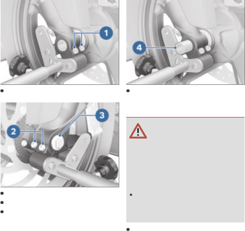
86 MAINTENANCE
Loosen clamping bolts 1.
Remove screw 3.
Loosen clamping bolts 2.
Press quick-release axle
slightly toward the inside, so
as to be better able to grip it
on the right-hand side.
Withdraw quick-release
axle 4, support the front
wheel when doing this.
ATTENTION
Removal of front wheel not
in compliance with correct
procedure
Damage to wheel speed
sensor
Note the wheel-speed
sensor when rolling out the
front wheel.
Set down front wheel and
roll forwards out of the front
suspension. In this process,
take care not to damage the
wheel speed sensor.

87
Remove spacer bush 5 from
the wheel hub.
Installing front wheel
WARNING
Use of a non-standard wheel
Malfunctions in ABS operation
See the information on the
effect of wheel size on the
ABS system at the start of
this chapter.
ATTENTION
Tightening threaded fasten-
ers to incorrect tightening
torque
Damage, or threaded fasten-
ers work loose
Always have the security
of the fasteners checked
by a specialist workshop,
preferably an authorised
BMW Motorrad dealer.
Lubricate the friction face of
spacer bush 5.
Lubricant
Optimoly TA
Insert spacer bush 5, turned
with the collar facing out, into
the wheel hub on the left-
hand side.
ATTENTION
Front wheel installed wrong
way round
Risk of accident
Note direction-of-rotation
arrows on tyre or rim.

88 MAINTENANCE
ATTENTION
Installation of front wheel
not in compliance with cor-
rect procedure
Damage to wheel speed
sensor
Note the wheel-speed
sensor when rolling in the
front wheel.
Roll the front wheel into pos-
ition between the front forks.
In this process, take care not
to damage the wheel speed
sensor.
Lubricate quick-release axle 4.
Lubricant
Optimoly TA
Lift the front wheel slightly
and install quick-release
axle 4.
Remove front-wheel stand
and firmly compress front
forks several times. Do not
operate the brake lever in this
process.
Install the front-wheel stand
( 73).
Install screw 3 and tighten to
specified torque. Counter-
hold quick-release axle on the
right-hand side.
Screw in front-wheel
quick-release axle
50 Nm
Tighten clamping bolts 2
to the specified tightening
torque.

89
Clamping screws in axle
holder
Tightening sequence: Tighten
screws six times in alternate
sequence
19 Nm
Tighten clamping bolts 1
to the specified tightening
torque.
Clamping screws in axle
holder
Tightening sequence: Tighten
screws six times in alternate
sequence
19 Nm
Remove the front-wheel
stand.
WARNING
Brake pads not lying against
the brake disc
Risk of accident due to
delayed braking effect.
Before driving, check that
the brakes respond without
delay.
Operate the brake several
times until the brake pads are
bedded.
Removing rear wheel
Lift the motorcycle, preferably
with a BMW Motorrad rear-
wheel stand.

90 MAINTENANCE
Install the rear-wheel stand
( 73).
Slip wooden chocks or sim-
ilar under the rear wheel to
prevent it from dropping out
after the quick-release axle
has been removed.
Press the brake caliper 1
against the brake disc 2.
Brake piston has been pushed
back.
Remove nut 6, using the ap-
propriate tool from the on-
board toolkit.
Remove washer.
Loosen lock nuts 3 on left and
right.
Tighten adjusting screws 4 on
left and right.
Remove chain tensioner 5 and
push the quick-release axle to
the right as far as it will go.
Remove quick-release axle 8
and remove chain tensioner 7.
Roll the rear wheel as far
forward as possible and
disengage chain 9 from the
sprocket.

91
When rolling the rear wheel
clear of the motorcycle, take
care not to damage wheel-
speed sensor 10.
Roll the rear wheel to the rear
and clear of the swinging arm
and at the same time pull
brake-caliper carrier 11 back
far enough to allow the rear
wheel to clear it.
The sprocket and the
spacer bushes on left and
right are loose fits in the wheel.
Make sure that these parts are
not damaged or get lost on re-
moval.
Installing rear wheel
WARNING
Use of a non-standard wheel
Malfunctions in ABS operation
See the information on the
effect of wheel size on the
ABS system at the start of
this chapter.
ATTENTION
Tightening threaded fasten-
ers to incorrect tightening
torque
Damage, or threaded fasten-
ers work loose
Always have the security
of the fasteners checked
by a specialist workshop,
preferably an authorised
BMW Motorrad dealer.
Roll the rear wheel on the
support into the swinging arm
as far as necessary to permit
the brake-caliper carrier to be
inserted.

92 MAINTENANCE
Set brake-caliper support 1
on guide 2.
When rolling the rear wheel
into position, take care not
to damage wheel-speed
sensor 10.
Roll the rear wheel further
into the swinging arm, while
pushing brake-caliper car-
rier 11 forward at the same
time.
Roll the rear wheel as far for-
ward as possible and loop
chain 9 over the sprocket.
Insert quick-release axle 8 and
chain tensioner 7 into the
swinging arm, brake-caliper
support and rear wheel, inter-
locking the quick-release axle
with the chain tensioner.

93
Insert left-hand chain ten-
sioner 5.
Install nut 6 with its washer,
but do not tighten the nut at
this point.
WARNING
Brake pads not lying against
the brake disc
Risk of accident due to
delayed braking effect.
Before driving, check that
the brakes respond without
delay.
Operate the brake several
times until the brake pads are
bedded.
Adjust the chain tension
( 93).
CHAIN
Adjusting chain tension
Make sure the ground is level
and firm and place the motor-
cycle on its stand.
Slacken nut 6.
Loosen lock nuts 3 on left and
right.
Use adjusting screws 4 on
left and right to adjust chain
tension.
Check the chain tension
( 94).
Make sure that the notch in
the top of chain tensioner 5 is
set to the same scale value on
left and right.
Tighten lock nuts 3 on left
and right to the specified
tightening torque.
Locknut of the final-
drive chain tensioning
screw
19 Nm
Tighten nut 6 to the specified
tightening torque.
Rear quick-release axle
in swinging arm
100 Nm
Once you have tightened the
rear wheel quick-release axle,

94 MAINTENANCE
complete the following tasks
again:
Check the chain tension
( 94).
Checking chain tension
Make sure the ground is level
and firm and place the motor-
cycle on its stand.
Turn the rear wheel until it
reaches the position with the
lowest amount of chain sag.
Use a screwdriver to push
chain 1 up and down at a
point midway between the
pinion and sprocket and
measure chain sag A.
Chain deflection
40...50 mm (Motorcycle with
no weight applied, supported
on its side stand)
If chain deflection is outside
permitted tolerance:
Adjust the chain tension
( 93).
Lubricating chain
ATTENTION
Inadequate cleaning and lub-
rication of the drive chain
Accelerated wear
Clean and lubricate the drive
chain at regular intervals.
Lubricate the drive chain
every third fuel stop.
Lubricate the chain more fre-
quently if the motorcycle is
ridden in wet, dusty or dirty
conditions.
Switch the ignition off and
select neutral.
Clean the drive chain with a
suitable cleaning product, dry
it and apply chain lubricant.
To prolong chain life,
BMW Motorrad recommends
the use of BMW Motorrad
chain lubricant, or:
Lubricant
Chain spray, O-ring compat-
ible
Wipe off excess lubricant.

95
Checking chain wear
Engage 1st gear.
Turn the rear wheel in the
normal direction of travel until
the chain is tensioned.
Determine the length of the
chain underneath the rear
wheel swinging arm above
the middle of 10 rivets in 3
different places.
Permissible chain length
max 144.30 mm (measured
from the centre of 10 rivets,
chain pulled taut)
If the chain has stretched to the
maximum permissible length:
Consult a specialist work-
shop, preferably an authorised
BMW Motorrad retailer.
Check whether a rivet head 1
has twisted out of line.
Rivet heads are parallel to the
chain centreline 2.
Chain riveting is OK.
If one or more rivet heads have
twisted out of line:
Consult a specialist work-
shop, preferably an authorised
BMW Motorrad retailer.
LIGHTING
Replacing LED light sources
WARNING
Vehicle overlooked in traffic
due to failure of the lights
on the vehicle
Safety risk
Always replace a faulty bulb
at the earliest possible op-
portunity. Consult a special-
ist workshop, preferably an
authorised BMW Motorrad
Retailer.

96 MAINTENANCE
All light sources of the vehicle
are LED light sources. The
service life of the LED light
sources is longer than the
presumed vehicle service life.
If an LED light source is faulty
contact a specialist workshop,
preferably an authorised
BMW Motorrad retailer.
CAUTION
JUMP-STARTING
Touching live parts of the
ignition system when the
engine is running
Electric shock
Do not touch parts of the
ignition system when the
engine is running.
ATTENTION
Excessive current flowing
when the motorcycle is
jump-started
Wiring smoulders/ignites or
damage to the on-board elec-
tronics
If the motorcycle has to be
jump-started connect the
leads to the battery termin-
als; never attempt to jump-
start the engine by connect-
ing leads to the on-board
socket.
ATTENTION
Contact between crocodile
clips of jump leads and
vehicle
Risk of short-circuit
Use jump leads fitted with
fully insulated crocodile clips
at both ends.

97
ATTENTION
Jump-starting with a voltage
greater than 12 V
Damage to the on-board
electronics
Make sure that the battery
of the donor vehicle does
not exceed a voltage of
12 V.
When jump-starting the en-
gine, do not disconnect the
battery from the on-board
electrical system.
Remove the seat ( 40).
Run the engine of the donor
vehicle during jump-starting.
Begin by connecting one end
of the red jump lead to the
positive terminal of the dis-
charged battery and the other
end to the positive terminal of
the donor battery.
Then connect one end of the
black jump lead to the neg-
ative terminal of the donor
battery, and the other end to
the negative terminal of the
discharged battery.
Start the engine of the vehicle
with the discharged battery
in the usual way; if the en-
gine does not start, wait a
few minutes before repeat-
ing the attempt in order to
protect the starter motor and
the donor battery.
Allow both engines to run for
a few minutes before discon-
necting the jump leads.
Disconnect the jump lead
from the negative terminal
first, then disconnect the
second lead from the positive
terminal.
Install the seat ( 41).
BATTERY
Maintenance instructions
Correct upkeep, recharging and
storage will prolong the life of
the battery and are essential if
warranty claims are to be con-
sidered.
Compliance with the points
below is important in order to
maximise battery life:
Keep the surface of the bat-
tery clean and dry.
Do not open the battery.
Do not top up with water.
Be sure to read and comply
with the instructions for char-
ging the battery on the fol-
lowing pages.
Do not turn the battery upside
down.

98 MAINTENANCE
ATTENTION
On-board electronics (e.g.
clock) draining connected
battery
Battery is deep-discharged;
this voids the guarantee
Connect a float charger to
the battery if the motorcycle
is to remain out of use for
more than four weeks.
Recharging connected battery
ATTENTION
Charging the battery that is
connected to the vehicle via
the battery terminals
Damage to the on-board
electronics
Disconnect the battery at
the battery terminals before
charging.
Disconnecting battery from
motorcycle ( 98).
Recharging disconnected
battery
Disconnecting battery from
motorcycle ( 98).
Charge the battery using a
suitable charger.
Comply with the operating
instructions of the charger.
Once the battery is fully
charged, disconnect the
charger's terminal clips from
the battery terminals.
The battery has to be re-
charged at regular inter-
vals in the course of a lengthy
period of disuse. See the in-
structions for caring for your
battery. Always fully recharge
the battery before restoring it
to use.
Connecting battery to motor-
cycle ( 99).
Disconnecting battery from
motorcycle
Make sure the ground is level
and firm and place the motor-
cycle on its stand.
Remove the seat ( 40).

99
ATTENTION
Battery not disconnected
in accordance with correct
procedure
Risk of short-circuit
Always proceed in compli-
ance with the specified dis-
connection sequence.
Disconnect negative battery
cable 1 first.
Then push protective cap 3
aside and disconnect positive
battery cable 2.
Connecting battery to
motorcycle
First connect positive battery
cable 2 and cover it with pro-
tective cap 3.
Then connect negative battery
cable 1.
Install the seat ( 41).
Removing battery
Remove the seat ( 40).
Disconnecting battery from
motorcycle ( 98).
Remove screw 1.

100 MAINTENANCE
Unhook retainer 1 on the left
and swing it up.
On the right, disengage the
retainer from battery tray 2.
The retainer is now attached
only to vehicle wiring har-
ness 3.
Push holder 1 complete with
wiring harness 3 to the right
out of the way.
The battery can now be re-
moved.
Lift battery 4 up and out.
Work it back and forth slightly
if it is difficult to remove.
Installing battery
Insert battery 4 into the bat-
tery compartment, positive
terminal on the right in the
forward direction of travel.
Engage the holder on the
right in battery tray 2.
Swing holder 1 down and en-
gage it on the left.
Wiring harness 3 is in the ini-
tial position.
Install screw 1.
Connecting battery to motor-
cycle ( 99).
Install the seat ( 41).
If the vehicle has been
disconnected from the
battery for a significant time,
the current date will have to
be entered in the instrument
cluster to guarantee correct
operation of the service display.
Set the clock ( 39).
Set the date ( 39).

101
FUSES
Replacing fuses
ATTENTION
Jumpering of blown fuses
Risk of short-circuit and fire
Never attempt to jumper a
blown fuse.
Always replace a defective
fuse with a new fuse of the
same amperage.
Switch off the ignition
( 35).
Make sure the ground is level
and firm and place the motor-
cycle on its stand.
Remove the seat ( 40).
Press latch 1.
Open fuse box 2.
Consult the fuse assignment
diagram below and, using the
gripping clamp, replace the
defective fuse.
Fuse assignment ( 101)
Close fuse box 2. Make sure
that lock 1 engages.
If fuse defects recur fre-
quently have the electric
circuits checked by a specialist
workshop, preferably an au-
thorised BMW Motorrad dealer.
Install the seat ( 41).
Fuse assignment
Fuse 1
20 A (Engine control unit)
Fuse 2
7.5 A (Heated grips, instru-
ment cluster, ABS pressure
modulator, engine control
unit, starter relay)
Fuse 3
30 A (Main fuse)
Fuse 4
20 A (ABS pressure modu-
lator)

102 MAINTENANCE
Fuse 5
15 A (Lighting, horn)
Fuse 6
7.5 A (Instrument cluster, dia-
gnosis)
Reserve fuses 7
There are another 3 spare
fuses (7.5 A, 20 A, 30 A) in
the fuse box.
DIAGNOSTIC CONNECTOR
Disengaging diagnostic
socket
CAUTION
Incorrect procedure followed
when loosening the dia-
gnostic connector for the
on-board diagnosis
Motorcycle experiences mal-
functions
Only have the diagnostic
connector loosened by a
specialist workshop or other
authorised persons during
your next BMW Service ap-
pointment.
Have the work performed
by appropriately trained
staff.
Refer to the vehicle manu-
facturer specifications.
Remove the seat ( 40).
Push in locks 1.
Disengage diagnostic
socket 2 from holder 3.
The interface to the diagnosis
and information system
can be connected to the
diagnostic connector 2.
Securing diagnostic socket
Disconnect the interface for
the diagnosis and information
system.
Insert diagnostic socket 2 into
holder 3.
The locks 1 engage.
Install the seat ( 41).
103

ACCESSORIES
09


106 ACCESSORIES
GENERAL NOTES
CAUTION
Use of other-make products
Safety risk
BMW Motorrad cannot ex-
amine or test each product
of outside origin to ensure
that it can be used on or
in connection with BMW
vehicles without constituting
a safety hazard. Country-
specific official authorisa-
tion does not suffice as as-
surance. Tests conducted
by these instances cannot
make provision for all oper-
ating conditions experienced
by BMW vehicles and, con-
sequently, they are not suffi-
cient in some circumstances.
Use only parts and accessor-
ies approved by BMW for
your vehicle.
BMW has conducted extensive
testing of the parts and access-
ory products to establish that
they are safe, functional and
suitable. Consequently, BMW
accepts responsibility for the
products. BMW accepts no li-
ability whatsoever for parts and
accessories that it has not ap-
proved.
All modifications must be in
compliance with legal require-
ments. Make sure that the
vehicle does not infringe the
national road-vehicle construc-
tion and use regulations applic-
able in your country.
Your authorised
BMW Motorrad retailer
can offer expert advice on the
choice of genuine BMW parts,
accessories and other products.
To find out more about ac-
cessories go to:
bmw-motorrad.com/equip-
ment
HEATED HANDLEBAR GRIPS
with heated grips
OA
Operating the heated
handlebar grips
Start the engine.
The heating in the heated
handlebar grips can be
activated only when the engine
is running.
The increase in power
consumption caused by
having the heated handlebar
grips switched on can drain the
battery if you are riding at low
engine speeds.
The handlebar grips have
two-stage heating. Stage
two is for heating the grips
quickly: it is advisable to switch

107
to stage one as soon as the
grips are warm.
Press the rocker switch 1
on the side with two dots to
switch on the high heater out-
put setting.
Press the rocker switch 1
on the side with one dot to
switch on the low heater out-
put setting.
Centre the rocker switch 1 to
switch the heating system off.
POWER SOCKET
with extra socket
OA
Connection of electrical
devices
You can start using electrical
devices connected to the mo-
torcycle's sockets only when
the ignition is switched on.
Cable routing
The cables from the power
sockets to the auxiliary
devices must be routed in
such a way that they do not
impede the rider.
The cable routing should not
restrict the steering angle or
obstruct handling.
The cables must not be
trapped.
TOPCASE
Installing topcase
with topcase
OA
WARNING
Topcase not properly se-
cured
Driving safety is impaired
The topcase must not
wobble and must be
secured free from play.
Pull carry handle 1 up as far
as it will go.

108 ACCESSORIES
Hook the topcase into lug-
gage carrier 4. Make sure
that hooks 2 are securely
seated in corresponding keep-
ers 3.
Push carry handle 1 down un-
til it engages.
Turn the key in the topcase
lock to position 1 and remove
the key.
Opening topcase
with topcase
OA
Turn the key in the topcase
lock to position 1.
Push lock barrel 1 forward.
Release lever 2 pops up.
Pull the release lever all the
way up.
The lid of the topcase opens.
Closing topcase
with topcase
OA

109
Pull release lever 1 up as far
as it will go.
Close the lid of the topcase
and hold it down. Check that
nothing is trapped between
the lid and the case.
The topcase can also be
closed when the lock is in
the LOCK position. In this case,
make sure that the key is not
left inside the topcase.
Push release lever 1 down
until it engages.
Turn the key in the topcase
lock to the LOCK position and
remove the key from the lock.
Removing topcase
with topcase
OA
Turn the key in the topcase
lock to position 1.
The handle pops out.
Pull carry handle 1 up as far
as it will go.
Lift the topcase at the rear
and remove it from the lug-
gage carrier.
Maximum payload and
maximum permissible speed
Note the maximum permissible
payload and the speed limit for
riding with topcase fitted, as
stated on the label inside the
topcase.

110 ACCESSORIES
Contact your authorised
BMW Motorrad dealer if you
cannot find your combination
of vehicle and topcase on the
label.
The values for the combination
described here are as follows:
Maximum speed for rid-
ing with a loaded top-
case
with topcase
OA
or
with topcase Light
OA
max 130 km/h
Payload of topcase
max 5 kg
LIGHT TOPCASE
Installing Light topcase
with topcase Light
OA
WARNING
Topcase not properly se-
cured
Driving safety is impaired
The topcase must not
wobble and must be
secured free from play.
Turn the key until it is vertical
in the lock.
Insert base 5 into slot 4.
Position mount 6 on hook 2.
Make sure that release lever 1
engages and that the topcase
is securely connected to ad-
apter 3.
To lock the release lever, turn
the key until it is horizontal in
the lock and pull it out.
Opening Light topcase
with topcase Light
OA
Turn the key until it is vertical
in the lock.
The release levers are
locked when the key is
in the horizontal position.

111
Push release lever 1 in the
direction of the arrow.
Open topcase lid 2.
Closing Light topcase
with topcase Light
OA
Turn the key until it is vertical
in the lock.
Close topcase lid 1. Check
that nothing is trapped
between lid and case and that
release lever 2 engages.
Turn the key in topcase lock 3
to the horizontal position and
remove the key.
The release levers are locked.
You can neither open the top-
case nor remove it from the
adapter.
Removing Light topcase
with topcase Light
OA
Turn the key until it is vertical
in the lock.
Push release lever 1 in the
direction of the arrow.
Lift the topcase at the rear
and remove it from 2 of ad-
apter 3.
Maximum payload and
maximum speed
with topcase Light
OA
Note the maximum payload
and the maximum permissible
speed.
Maximum speed for rid-
ing with a loaded top-
case
with topcase
OA
or
with topcase Light
OA
max 130 km/h

112 ACCESSORIES
Payload of topcase
max 3 kg
113

CARE
10


116 CARE
CARE PRODUCTS
BMW Motorrad recom-
mends that you use the
cleaning and care products
you can obtain from your
authorised BMW Motorrad
retailer. The substances in
BMW Care Products have
been tested in laboratories
and in practice; they provide
optimised care and protection
for the materials used in your
vehicle.
ATTENTION
Use of unsuitable cleaning
and care products
Damage to vehicle parts
Do not use solvents such
as cellulose thinners, cold
cleaners, fuel or the like,
and do not use cleaning
products that contain alco-
hol.
ATTENTION
Use of strongly acidic or
strongly alkaline cleaning
agents
Damage to vehicle parts
Dilute in accordance with
the dilution ratio stated on
the packaging of the clean-
ing agent.
Do not use strongly acidic
or strongly alkaline cleaning
agents.
WASHING THE VEHICLE
BMW Motorrad recommends
that you use BMW insect re-
mover to soften and wash off
insects and stubborn dirt on
painted parts prior to washing
the motorcycle.
To prevent stains, do not wash
the motorcycle immediately
after it has been exposed to
strong sunlight and do not
wash it in the sun.
Remove dirt from the fork legs
at regular intervals. Make sure
that the vehicle is washed fre-
quently, especially during the
winter months.
To remove road salt, clean the
motorcycle with cold water im-
mediately after every trip.

117
WARNING
Wet brake discs and brake
pads after vehicle wash,
after riding through water
and in rainy conditions
Diminished braking effect,
risk of accident
Apply the brakes in good
time to allow the friction
and heat to dry the brake
discs and brake pads.
ATTENTION
Effect of road salt intensi-
fied by warm water
Corrosion
Use only cold water to wash
off road salt.
ATTENTION
Damage due to high water
pressure from high pressure
cleaners or steam cleaners
Corrosion or short circuit,
damage to labels, seals, hy-
draulic brake system, elec-
trical system and the motor-
cycle seat
Exercise restraint when us-
ing a steam jet or high pres-
sure cleaning equipment.
The case and topcase do
not have any surface coat-
ing. The following care steps
will ensure the best-possible
appearance:
Remove road salt and corrosive
deposits immediately at the
end of the journey with cold
water.
CLEANING EASILY DAMAGED
COMPONENTS
Plastics
ATTENTION
Use of unsuitable cleaning
agents
Damage to plastic surfaces
Do not use cleaning agents
that contain alcohol, solvents
or abrasives.
Do not use insect-remover
pads or cleaning pads with
hard, scouring surfaces.
Trim panel components
Clean trim panel components
with water and BMW Motorrad
solvent cleaner.
Windscreen and lenses made
of plastic
Remove dirt and insects with a
soft sponge and plenty of wa-
ter.
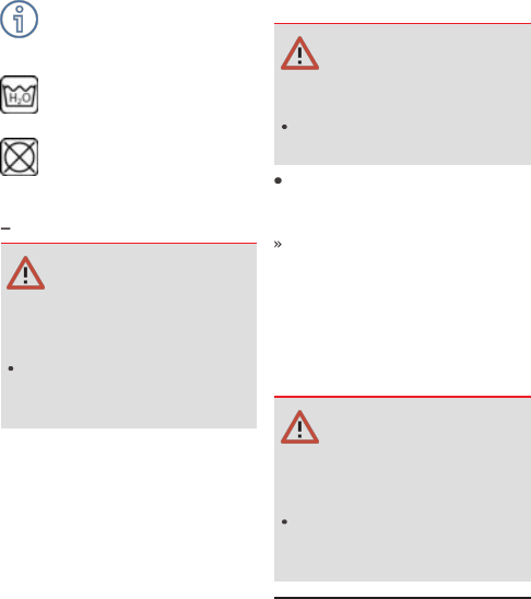
118 CARE
Soften stubborn dirt and
insects by covering the
affected areas with a wet cloth.
Clean with water and
sponge only.
Do not use any chemical
cleaning agents.
Light topcase
with topcase Light
OA
ATTENTION
Use of unsuitable cleaning
and care products
Damage to the surface
Clean the surface using
only water and a microfibre
cloth.
Chrome
Carefully clean chrome sections
with a generous amount
of water and motorcycle
cleaner from the care series
BMW Motorrad Care Products.
This applies especially where
road salt has been in use.
For an additional treatment, use
BMW Motorrad metal polish.
Radiator
ATTENTION
Bending of radiator fins
Damage to radiator fins
Take care not to bend the
radiator fins when cleaning.
Clean radiator regularly. Use a
hose with low water pressure,
for example, to do this.
This prevents the engine from
overheating due to insufficient
cooling.
Rubber
Treat rubber components with
water or BMW rubber-care
products.
ATTENTION
Application of silicone
sprays to rubber seals
Damage to the rubber seals
Do not use silicone sprays
or care products that con-
tain silicon.
CARE OF PAINTWORK
The long-term effects of mater-
ials that are damaging to paint
can be prevented by regular
vehicle washes, particularly if
your vehicle is ridden in areas
susceptible to high levels of air
pollution or natural contamina-

119
tion, for example tree resin or
pollen.
Particularly aggressive mater-
ials, however, should be re-
moved immediately, otherwise
changes to or discolouration
of the paint can result. These
include, for example, spilled
fuel, oil, grease, brake fluid or
bird excrement. For this, we
recommend BMW Motorrad
solvent cleaner followed by
BMW Motorrad gloss polish
for preservation.
Contamination of the paint sur-
face can be seen particularly
clearly after a vehicle wash.
These areas should be cleaned
immediately using benzine or
spirit, applied with a clean cloth
or cotton pad. BMW Motorrad
recommends that tar spots be
removed using BMW tar re-
mover. The paint should then
be preserved in these areas.
VEHICLE PRESERVATION
If water no longer rolls off the
paint, the paint must be pre-
served.
For paint preservation,
BMW Motorrad recommends
the use of BMW Motorrad
gloss polish or agents contain-
ing carnauba wax or synthetic
wax.
LAYING UP THE MOTOR-
CYCLE
Clean the motorcycle.
Refuel the motorcycle.
Fuel additives clean the
fuel injection system and
the combustion zone. It is ad-
visable to use fuel additives
when the engine is operated
with low-grade fuel or if the
vehicle is to be out of use for
a lengthy period of time. More
information is available from
your authorised BMW Motorrad
retailer.
Remove the battery ( 99).
Spray the clutch-lever and
brake-lever pivots and the
centre-stand and side-stand
pivot mounts with a suitable
lubricant.
Coat bright metal and
chrome-plated parts with
an acid-free grease (e.g.
Vaseline).
Stand the motorcycle in a dry
room in such a way that there
is no load on either wheel
(preferably using the front-
wheel and rear-wheel stands
from BMW Motorrad).
121

TECHNICAL DATA
11

124 TECHNICAL DATA
TROUBLESHOOTING CHART
The engine doesn't start.
Possible cause Rectification
Side stand extended and gear
engaged
Retract the side stand.
Kill switch activated Set emergency-off switch to
operation mode ( 35).
Gear engaged and clutch not
disengaged
Operate the clutch or put the
transmission into idle so that
the idle mode indicator light
lights up.
No fuel in tank Refuelling ( 59).
Battery flat Recharging disconnected bat-
tery ( 98).

125
SCREW CONNECTIONS
Front wheel Value Valid
Screw in front-wheel
quick-release axle
M12 x 20 50 Nm
Clamping screws in
axle holder
M8 x 30 Tightening sequence:
Tighten screws six times in
alternate sequence
19 Nm
Rear wheel Value Valid
Locknut of the final-
drive chain tensioning
screw
M8 19 Nm
Rear quick-release
axle in swinging arm
M18 x 1.5 100 Nm
Mirrors Value Valid
Right mirror (lock
nut) to adapter
M10 x 1.25 Left-hand thread, 22 Nm
Left mirror (lock nut)
to adapter
M10 x 1.25 22 Nm

126 TECHNICAL DATA
FUEL
Recommended fuel grade Regular unleaded (max-
imum 15 % ethanol, E15)
91 ROZ/RON
87 AKI
Usable fuel capacity approx. 11.5 l
Fuel reserve approx. 1 l
Fuel consumption 3.3 l/100 km, according to
WMTC
CO2 emission 77 g/km, according to WMTC
Exhaust emissions standard Euro 5
ENGINE OIL
Engine oil, capacity approx. 1.65 l, with filter
change
Specification SAE 5W-40, API SJ /
JASO MA2, Additives (e.g.
molybdenum-based) are
not permissible because
they can attack coated
components of the engine,
BMW Motorrad recommends
BMW Motorrad ADVANTEC
Ultimate oil.
Engine oil, quantity for topping
up
0.18 l, Difference between
MIN and MAX
BMW recommends

127
ENGINE
Engine number location Crankcase, bottom right
Engine type A82A03B
Engine design Water-cooled 1-cylinder 4-
stroke engine with four valves
operated via rocker arms, two
overhead camshafts and coun-
terbalance shaft
Displacement 313 cm
3
Cylinder bore 80 mm
Piston stroke 62.1 mm
Compression ratio 10.9:1
Nominal capacity 25 kW, at engine
speed: 9250 min
-1
Torque 28 Nm, at engine
speed: 7250 min
-1
Maximum engine speed max 10800 min
-1
Idle speed 1600
±100
min
-1
, Engine at
regular operating temperature
CLUTCH
Clutch type Multi-plate oil-bath clutch
Clutch-lever play 1...2 mm, on the manual con-
trols, handlebars in straight-
ahead position, with cold en-
gine

128 TECHNICAL DATA
TRANSMISSION
Type of transmission Claw-shift 6-speed gearbox,
integrated into engine block
Gearbox transmission ratios 3.083, Primary transmission
ratio
1:3.000, 1st gear
1:2.063, 2nd gear
1:1.588, 3rd gear
1:1.286, 4th gear
1:1.095, 5th gear
1:0.955, 6th gear
FINAL DRIVE
Type of final drive Chain drive
Chain deflection 40...50 mm, Motorcycle with
no weight applied, supported
on its side stand
Permissible chain length max 144.30 mm, measured
from the centre of 10 rivets,
chain pulled taut
Final drive, number of teeth
(Pinion / sprocket)
16/40
Secondary transmission ratio 2.500
FRAME
Frame type Tubular spaceframe
Type plate location Frame, left
Position of the vehicle identi-
fication number
Frame, front right at steering
head

129
CHASSIS AND SUSPENSION
Front wheel
Type of front suspension Upside-down telescopic fork
Spring travel, front 180 mm, at wheel
Rear wheel
Type of rear suspension Two-arm aluminium swing
arm
Spring travel, rear 180 mm, at wheel
BRAKES
Front wheel
Type of front brake Single-disc brake, 4-piston ra-
dial brake caliper
Brake-pad material, front Sintered metal
Brake disc thickness, front 5.0 mm, when new
min 4.5 mm, Wear limit
Rear wheel
Type of rear brake 1-piston floating caliper
Brake-pad material, rear Organic material
Brake disc thickness, rear 4.5 mm, when new
min 4 mm, Wear limit
WHEELS AND TYRES
Recommended tyre combina-
tions
Your authorised
BMW Motorrad retailer
will be happy to supply an up-
to-date list of the approved
wheel/tyre combinations, or
you can check the information
posted on the internet at
bmwmotorrad.com/service.
Speed category, front/rear
tyres
h, required at least: 210 km/h

130 TECHNICAL DATA
Front wheel
Front-wheel type Aluminium cast wheel
Front-wheel rim size 2.50" x 19"
Tyre designation, front 110/80 R 19
Load index, front tyre min. 59
Permissible front-wheel imbal-
ance
max 5 g
Rear wheel
Rear-wheel type Aluminium cast wheel
Rear wheel rim size 4.0" x 17"
Tyre designation, rear 150/70 R 17
Load index, rear tyre min. 69
Permissible rear-wheel imbal-
ance
max 5 g
Tyre pressure
Tyre pressure, front 1.7 bar, with cold tyre; one-up
and two-up
Tyre pressure, rear 1.9 bar, with cold tyre; one-up
and two-up
ELECTRICAL SYSTEM
Fuses
Fuse 1 20 A, Engine control unit
Fuse 2 7.5 A, Heated grips, instru-
ment cluster, ABS pressure
modulator, engine control unit,
starter relay
Fuse 3 30 A, Main fuse
Fuse 4 20 A, ABS pressure modulator
Fuse 5 15 A, Lighting, horn
Fuse 6 7.5 A, Instrument cluster, dia-
gnosis

131
Battery
Battery type AGM
Battery rated voltage 12 V
Battery rated capacity 8 Ah
Spark plugs
Spark plugs, manufacturer and
designation
NGK LMAR8J-9E
Lighting
Bulb for low-beam and high-
beam headlight
LED
Bulb for parking light LED
Bulb for tail light/brake light LED
Light source for the number
plate light
LED
Bulbs for turn indicators LED
Bulb for auxiliary headlight LED
DIMENSIONS
Length of motorcycle 2075 mm, over number-plate
carrier
Height of motorcycle 1315 mm, over mirrors, at DIN
unladen weight
1230 mm, without mirrors, at
DIN unladen weight
Width of motorcycle 880 mm, with mirrors
860 mm, without mounted
parts
Height of rider's seat 835 mm, Without rider, at DIN
unladen weight
Rider's inside-leg arc, heel to
heel
1870 mm, Without rider, at
DIN unladen weight

132 TECHNICAL DATA
WEIGHTS
Vehicle kerb weight 175 kg, DIN unladen weight,
ready for road, 90 % load of
fuel, without optional equip-
ment (OE)
Wheel load, front, at unladen
weight
82 kg
Permissible wheel load, front max 120 kg
Wheel load, rear, at unladen
weight
90 kg
Permissible wheel load, rear max 225 kg
Permissible gross vehicle
weight
345 kg
Maximum payload 175.5 kg
PERFORMANCE FIGURES
Top speed 143 km/h
ACCESSORIES
Maximum speed for riding
with a loaded topcase
with topcase
OA
or
with topcase Light
OA
max 130 km/h
Payload of topcase max 5 kg
133

SERVICE
12


136 SERVICE
REPORTING SAFETY-RELEVANT DEFECTS
with Canada export
NV
If you think that your motorcycle has a fault which may cause
an accident, injury or death, you must inform the NHTSA (Na-
tional Highway Traffic Safety Administration) immediately and
BMW of North America, LLC.
If the NHTSA receives other similar complaints, it may open an
investigation. If it finds that a safety defect exists in a group of
vehicles, the NHTSA may order the manufacturer to perform a
recall and remedy campaign. However, the NHTSA cannot be-
come involved in individual problems between you, your retailer,
or BMW of North America, LLC.
You can contact the NHTSA by calling the Vehicle Safety hotline
on 1–888–327–4236 (teletypewriter TTY for the hearing
impaired: 1–800–424–9153) for free, by visiting the website
at http:// www.safercar.gov or by writing to Administrator,
NHTSA, 400 Seventh Street, SW., Washington, DC 20590.
Further information on vehicle safety is available at http://
www.safercar.gov.
Canadian customers who wish to report a safety-related defect
to Transport Canada, Defect Investigations and Recalls can call
the toll-free hotline 1–800–333–0510. You can also obtain other
information about motor vehicle safety from http:// www.tc.gc.ca/
roadsafety.

137
BMW MOTORRAD SERVICE
BMW Motorrad has an extens-
ive network of dealerships in
place to look after you and
your motorcycle in more than
100 countries. Authorised
BMW Motorrad retailers have
the technical information and
the technical expertise to carry
out reliably all maintenance and
repair work on your BMW.
You can locate the nearest au-
thorised BMW Motorrad re-
tailer by visiting our website:
bmw-motorrad.com
WARNING
Maintenance and repair
work not in compliance with
correct procedure
Risk of accident due to con-
sequential damage
BMW Motorrad recom-
mends having work of
this nature carried out on
the vehicle by a specialist
workshop, preferably an
authorised BMW Motorrad
dealer.
In order to help ensure
that your BMW is always
in optimum condition,
BMW Motorrad recommends
compliance with the mainten-
ance intervals specified for your
motorcycle.
Have all maintenance and
repair work carried out
confirmed in the "Service"
chapter in this manual. Evid-
ence of regular maintenance
is essential for generous
treatment of claims submitted
after the warranty period has
expired.
Your authorised
BMW Motorrad retailer
can provide information on
BMW services and the work
undertaken as part of each
service.
BMW MOTORRAD SERVICE
HISTORY
Entries
Maintenance work that has
been carried out is entered in
the proof of maintenance. The
entries are like a Service Book-
let and provide proof of regular
maintenance.
When an entry is made in the
electronic service booklet of
the vehicle, service-relevant
data is saved in the central IT
systems of BMW AG, Munich,
Germany.
If there is a change in vehicle
owner, the data saved in the
electronic service booklet

138 SERVICE
can also be viewed by
the new vehicle owner. A
BMW Motorrad retailer or a
specialist workshop can also
view data that is stored in the
electronic service booklet.
Objection
The vehicle owner can object
to entries being made by the
BMW Motorrad retailer or a
specialist workshop in the elec-
tronic service booklet along
with the corresponding storage
of data in the vehicle and trans-
fer of data to the vehicle man-
ufacturer for the period of time
that they are the vehicle owner.
In this instance, no entry is
made in the electronic service
booklet of the vehicle.
BMW MOTORRAD MOBILITY
SERVICES
As the owner of a new BMW
motorcycle, in the event of a
breakdown you can benefit
from the protection afforded
by the various BMW Motorrad
mobility services (e.g. BMW
Mobile Service, breakdown
service, vehicle recovery
service).
Your authorised
BMW Motorrad dealer
will be happy provide informa-
tion about the mobility services
available to you.
MAINTENANCE WORK
BMW pre-delivery check
Your authorised
BMW Motorrad dealer
conducts the BMW pre-delivery
check before handing over the
vehicle to you.
BMW Running-in check
Mileage until the run-
ning-in check
500...1200 km
BMW Service
The BMW Service is carried out
once a year; the extent of ser-
vicing can vary, depending on
the age of the vehicle and the
distance it has covered. Your
authorised BMW Motorrad
dealer confirms that the service
work has been carried out and
enters the date when the next
service will be due.
Riders who cover long dis-
tances in a year might have
to bring in their vehicles for
service before the next sched-
uled date. It is to allow for
these cases that a maximum
odometer reading is entered
as well in the confirmation of
service. Servicing has to be
brought forward if this odo-
139
meter reading is reached be-
fore the next scheduled date
for the service.
The service-due indicator in
the multifunction display re-
minds you about one month
or 1000 km in advance when
the time for a service is ap-
proaching, on the basis of the
programmed values.
To find out more about service
go to:
bmw-motorrad.com/service
The maintenance tasks neces-
sary for your vehicle are set out
in the maintenance schedule
below:

140 SERVICE
MAINTENANCE SCHEDULE
1 BMW running-in check (in-
cluding oil change)
2 Standard BMW service
3 Engine-oil change, with
filter
4 Replace air filter element
5 Replace spark plug
6 Check valve clearance
7 Oil change in the tele-
scopic forks
8 Replace fuel filters and fuel
hoses
9 Replace intake silencer
hoses for the cylinder head
and tank vent valve
10 Change brake fluid, entire
system
a
annually or every
10000 km (whichever
comes first)
b
for the first time after one
year, then every 2 years
c
every 40000 km or every
4 years (whichever comes
first)

141
MAINTENANCE CONFIRMATIONS
BMW Service standard scope
The repair tasks in the BMW Service standard scope are listed
below. The actual scope of maintenance work applicable for your
vehicle may vary.
Performing vehicle test with BMW Motorrad diagnosis system
Checking coolant level
Checking/adjusting clutch play
Check throttle cable for play
Checking front brake pads and brake discs for wear
Checking rear brake pads and brake disc for wear
Visual inspection of the brake lines, brake hoses and connec-
tions
Checking tyre pressure and tread depth
Checking and lubricating the chain drive
Checking brake-fluid level, front wheel brake
Checking brake-fluid level, rear wheel brake
Checking steering-head bearing
Lubricating side stand
Check lighting and signalling system
Function test, engine start suppression
Final inspection and check for road safety
Setting service-due date and countdown distance with
BMW Motorrad diagnosis system
Checking battery state of charge
Confirming BMW service in on-board literature

142 SERVICE
BMW pre-delivery check
carried out
at
Stamp, signature
BMW Running-in Check
carried out
at
Odometer reading
Next service
at the latest
at
or, when reached earlier
Odometer reading
Stamp, signature

143
BMW Service
carried out
at
Odometer reading
Next service
at the latest
at
or, when reached earlier
Odometer reading
Work performed
Yes No
BMW Service
Oil change, engine, with filter
Checking valve clearance
Renewing air cleaner insert
Oil change in telescopic front forks
Renewing all spark plugs
Replacing fuel filters and fuel hoses (at main-
tenance)
Replace hoses from intake silencer to cyl-
inder head and tank vent valve (at mainten-
ance)
Change brake fluid in entire system
Notes
Stamp, signature

144 SERVICE
BMW Service
carried out
at
Odometer reading
Next service
at the latest
at
or, when reached earlier
Odometer reading
Work performed
Yes No
BMW Service
Oil change, engine, with filter
Checking valve clearance
Renewing air cleaner insert
Oil change in telescopic front forks
Renewing all spark plugs
Replacing fuel filters and fuel hoses (at main-
tenance)
Replace hoses from intake silencer to cyl-
inder head and tank vent valve (at mainten-
ance)
Change brake fluid in entire system
Notes
Stamp, signature

145
BMW Service
carried out
at
Odometer reading
Next service
at the latest
at
or, when reached earlier
Odometer reading
Work performed
Yes No
BMW Service
Oil change, engine, with filter
Checking valve clearance
Renewing air cleaner insert
Oil change in telescopic front forks
Renewing all spark plugs
Replacing fuel filters and fuel hoses (at main-
tenance)
Replace hoses from intake silencer to cyl-
inder head and tank vent valve (at mainten-
ance)
Change brake fluid in entire system
Notes
Stamp, signature

146 SERVICE
BMW Service
carried out
at
Odometer reading
Next service
at the latest
at
or, when reached earlier
Odometer reading
Work performed
Yes No
BMW Service
Oil change, engine, with filter
Checking valve clearance
Renewing air cleaner insert
Oil change in telescopic front forks
Renewing all spark plugs
Replacing fuel filters and fuel hoses (at main-
tenance)
Replace hoses from intake silencer to cyl-
inder head and tank vent valve (at mainten-
ance)
Change brake fluid in entire system
Notes
Stamp, signature

147
BMW Service
carried out
at
Odometer reading
Next service
at the latest
at
or, when reached earlier
Odometer reading
Work performed
Yes No
BMW Service
Oil change, engine, with filter
Checking valve clearance
Renewing air cleaner insert
Oil change in telescopic front forks
Renewing all spark plugs
Replacing fuel filters and fuel hoses (at main-
tenance)
Replace hoses from intake silencer to cyl-
inder head and tank vent valve (at mainten-
ance)
Change brake fluid in entire system
Notes
Stamp, signature

148 SERVICE
BMW Service
carried out
at
Odometer reading
Next service
at the latest
at
or, when reached earlier
Odometer reading
Work performed
Yes No
BMW Service
Oil change, engine, with filter
Checking valve clearance
Renewing air cleaner insert
Oil change in telescopic front forks
Renewing all spark plugs
Replacing fuel filters and fuel hoses (at main-
tenance)
Replace hoses from intake silencer to cyl-
inder head and tank vent valve (at mainten-
ance)
Change brake fluid in entire system
Notes
Stamp, signature

149
BMW Service
carried out
at
Odometer reading
Next service
at the latest
at
or, when reached earlier
Odometer reading
Work performed
Yes No
BMW Service
Oil change, engine, with filter
Checking valve clearance
Renewing air cleaner insert
Oil change in telescopic front forks
Renewing all spark plugs
Replacing fuel filters and fuel hoses (at main-
tenance)
Replace hoses from intake silencer to cyl-
inder head and tank vent valve (at mainten-
ance)
Change brake fluid in entire system
Notes
Stamp, signature

150 SERVICE
BMW Service
carried out
at
Odometer reading
Next service
at the latest
at
or, when reached earlier
Odometer reading
Work performed
Yes No
BMW Service
Oil change, engine, with filter
Checking valve clearance
Renewing air cleaner insert
Oil change in telescopic front forks
Renewing all spark plugs
Replacing fuel filters and fuel hoses (at main-
tenance)
Replace hoses from intake silencer to cyl-
inder head and tank vent valve (at mainten-
ance)
Change brake fluid in entire system
Notes
Stamp, signature

151
BMW Service
carried out
at
Odometer reading
Next service
at the latest
at
or, when reached earlier
Odometer reading
Work performed
Yes No
BMW Service
Oil change, engine, with filter
Checking valve clearance
Renewing air cleaner insert
Oil change in telescopic front forks
Renewing all spark plugs
Replacing fuel filters and fuel hoses (at main-
tenance)
Replace hoses from intake silencer to cyl-
inder head and tank vent valve (at mainten-
ance)
Change brake fluid in entire system
Notes
Stamp, signature

152 SERVICE
BMW Service
carried out
at
Odometer reading
Next service
at the latest
at
or, when reached earlier
Odometer reading
Work performed
Yes No
BMW Service
Oil change, engine, with filter
Checking valve clearance
Renewing air cleaner insert
Oil change in telescopic front forks
Renewing all spark plugs
Replacing fuel filters and fuel hoses (at main-
tenance)
Replace hoses from intake silencer to cyl-
inder head and tank vent valve (at mainten-
ance)
Change brake fluid in entire system
Notes
Stamp, signature

153
BMW Service
carried out
at
Odometer reading
Next service
at the latest
at
or, when reached earlier
Odometer reading
Work performed
Yes No
BMW Service
Oil change, engine, with filter
Checking valve clearance
Renewing air cleaner insert
Oil change in telescopic front forks
Renewing all spark plugs
Replacing fuel filters and fuel hoses (at main-
tenance)
Replace hoses from intake silencer to cyl-
inder head and tank vent valve (at mainten-
ance)
Change brake fluid in entire system
Notes
Stamp, signature

154 SERVICE
BMW Service
carried out
at
Odometer reading
Next service
at the latest
at
or, when reached earlier
Odometer reading
Work performed
Yes No
BMW Service
Oil change, engine, with filter
Checking valve clearance
Renewing air cleaner insert
Oil change in telescopic front forks
Renewing all spark plugs
Replacing fuel filters and fuel hoses (at main-
tenance)
Replace hoses from intake silencer to cyl-
inder head and tank vent valve (at mainten-
ance)
Change brake fluid in entire system
Notes
Stamp, signature

155
SERVICE CONFIRMATIONS
The table is used to verify maintenance and repair work as well
as installed optional accessories and purchased special promo-
tions.
Work performed Odometer
reading
Date

156 SERVICE
Work performed Odometer
reading
Date
157
158 INDEX
A
Abbreviations and symbols, 4
ABS
Engineering details, 66
Indicator and warning
light, 28
Self-diagnosis, 55
Accessories
General notes, 106
Power socket, 107
Topcase, 107, 110
Anti-lock brake system ABS, 57
Average values
Displaying average consump-
tion (CONS1), 38
Displaying average speed
(SPEED), 38
resetting, 40
B
Battery
connecting to motorcycle, 99
disconnecting from
motorcycle, 98
installing, 100
Maintenance instructions, 97
Position on the vehicle, 16
recharging connected
battery, 98
recharging disconnected
battery, 98
removing, 99
Technical data, 131
Vehicle voltage is too low, 26
Beam throw
adjusting, 45
Brake fluid
Checking fluid level, front, 78
Checking fluid level, rear, 79
Reservoir, front, 15
Reservoir, rear, 15
Brake pads
checking front, 76
checking rear, 77
Running in, 56
Brakes
Adjusting handlebar levers, 46
Checking function, 76
Safety instructions, 57
Technical data, 129
C
Care
Care products, 116
Chrome, 118
Paintwork preservation, 119
Plastics, 117
Radiator, 118
Rubber, 118
Trim panel components, 117
Washing the vehicle, 116
Chain
Adjusting tension, 93
Adjustment values, 14
Checking tension, 94
Checking wear, 95
Lubricating, 94
Chassis and suspension
Technical data, 129
Checklist, 53
Clock
adjusting, 39
159
Clutch
Adjusting handlebar levers, 47
Adjusting play, 82
Checking function, 81
Checking play, 81
Technical data, 127
Coolant
Checking fill level, 82
Fill-level indicator, 15
topping up, 83
Warning light for overheat-
ing, 26
Coolant temperature
Displaying (ENGIN), 38
too high, 26
Currency, 5
D
Date
adjusting, 39
Displaying (DATE), 38
Service due date, 29
Daytime riding lights, 36
Diagnostic connector
disengaging, 102
securing, 102
Dimensions
Technical data, 131
Distance recorders
resetting, 39
E
Electrical system
Technical data, 130
Emergency off switch (kill
switch)
Emergency-off, 35
operating, 35
Operation mode, 35
Position on the vehicle, 18
Engine, 27, 28
In emergency operation, 26
parking, 35
Severe fault, 27
starting, 53
Technical data, 127
Engine oil
Checking fill level, 74
Oil filler opening, 14
Technical data, 126
topping up, 74, 75
Equipment, 5
F
Final drive
Technical data, 128
Frame
Technical data, 128
Front-wheel stand
installing, 73
Fuel
Displaying current consump-
tion (CONSA), 38
Filler neck, 15, 59
Fuel grade, 59
refuelling, 59
Technical data, 126
Fuel reserve
Range, 30
Telltale light, 29
Fuel reserve indicator light, 29
Fuses
Position on the vehicle, 16
replacing, 101
Technical data, 130
G
General views
Instrument cluster, 19
Left multifunction switch, 17
Left side of vehicle, 14
160 INDEX
Multifunction display, 23
Right multifunction switch, 18
Right side of vehicle, 15
Underneath the seat, 16
Warning and indicator
lights, 22
H
Headlight
adjusting, 44
Adjusting headlight beam
throw, 45
Adjustment for driving on left/
driving on right, 44
Headlight beam throw and
spring preload, 44
Headlight flasher
operating, 37
Heated handlebar grips
operating, 106
High-beam headlight
switching on, 36
Horn, 17
I
Ignition
switching off, 35
switching on, 34
Indicator lights, 19
Fuel reserve, 29
Overview, 22
Instrument cluster
Overview, 19
Photosensor, 19
Redline warning, 19
Warning and indicator
lights, 19
J
Jump-starting, 96
K
Keys, 34
L
Laying up, 119
Lighting
Replacing LED light
sources, 95
Technical data, 131
Lights
Adjusting headlight, 44
Control, 17
Daytime riding light, 36
Headlight flasher, operat-
ing, 37
High-beam headlight,
operating, 36
Low-beam headlight, 35
Side light, 35
Luggage
Instructions for loading, 50
Luggage carrier, 15
M
Maintenance
general notes, 72
Maintenance intervals, 138
Maintenance schedule, 140
Maintenance confirma-
tions, 141
Mirrors
adjusting, 44
Mobility services, 138
Motorcycle
care, 114
cleaning, 114
lashing, 61
laying up, 119
parking, 58
restoring to use, 120
161
Multifunction display, 19
Overview, 23
Selecting display, 38
Multifunction switch
Overview, left side, 17
Overview, right side, 18
O
Odometer
Displaying (ODO), 38
P
Parking, 58
Performance figures
Technical data, 132
Photosensor, 19
Power socket
Notes on use, 107
Position on the vehicle, 14
Pre-Ride-Check, 54
R
Range
Displaying (RANGE), 38
Rear-wheel stand
installing, 73
Redline warning, 56
Refuelling, 59
Fuel grade, 59
Rev. counter
Rev. counter, 31
Rider's Manual
Position on the vehicle, 16
Running in, 55
S
Safety instructions
for brakes, 57
for riding, 50
Screw connections, 125
Seat
installing, 41
Lock, 14
removing, 40
Service, 137
Display, 29
Reporting safety-relevant
defects, 136
Service history, 137
Service-due indicator, 29
Settings
Displaying (SETUP), 38
Headlight, 44
Mirrors, 44
Spring preload, 45
Spark plugs
Technical data, 131
Speedometer, 23
Spring preload
Adjuster, rear, 14
adjusting, 45
Starting, 53
Control, 18
Steering lock
Locking, 34
T
Technical data
Battery, 131
Brakes, 129
Chassis and suspension, 129
Clutch, 127
Dimensions, 131
Electrical system, 130
Engine, 127
Engine oil, 126
Final drive, 128
Frame, 128
Fuel, 126
Fuses, 130
162 INDEX
General notes, 5
Lighting, 131
Performance figures, 132
Spark plugs, 131
Standards, 5
Transmission, 128
Weights, 132
Wheels and tyres, 129
Toolkit
Contents, 72
Position on the vehicle, 16
Topcase
operating, 107, 110
Torques, 125
Transmission
Technical data, 128
Trim panels
Removing and installing front
trim panel, 45
Trip recorder
Displaying (TRIP1, TRIP2), 38
Troubleshooting chart, 124
Turn indicators
Control, 17
operating, 37
Type plate
Position on the vehicle, 14
Tyres
Checking tread depth, 83, 84
Checking tyre pressure, 83
Pressures, 130
Running in, 56
Technical data, 129
Top speed, 51
Tyre pressures table, 14
V
Vehicle Identification Number
Position on the vehicle, 15
VIN
Vehicle Identification
Number, 15
W
Warning indicator lights, 27, 28
ABS, 28
Coolant temperature, 26
Engine warning, 27
Mode of presentation, 24
Overtemperature, 26
Symbol for engine electron-
ics, 26
Warning light, drive malfunc-
tion, 27, 28
Warning lights, 19
On-board voltage, 26
Overview, 22
Warnings, overview, 25
Weights
Payload table, 14
Technical data, 132
Wheels
Change of size, 85
Checking rims, 84
Installing front wheel, 87
Installing rear wheel, 91
Removing front wheel, 85
Removing rear wheel, 89
Technical data, 129
Details described or illustrated
in this booklet may differ from
the vehicle's actual specific-
ation as purchased, the ac-
cessories fitted or the national-
market specification. No claims
will be entertained as a result
of such discrepancies.
Dimensions, weights, fuel con-
sumption and performance
data are quoted to the custom-
ary tolerances.
The right to modify designs,
equipment and accessories is
reserved.
Errors and omissions excepted.
© 2020 Bayerische Motoren
Werke Aktiengesellschaft
80788 Munich, Germany
Not to be reproduced by any
means whatsoever, wholly or in
part, without the written per-
mission of BMW Motorrad,
After Sales.
Original rider’s manual, printed
in Germany.

Important data for refuelling:
Fuel
Recommended fuel grade
Regular unleaded (max-
imum 15 % ethanol, E15)
91 ROZ/RON
87 AKI
Usable fuel capacity approx. 11.5 l
Fuel reserve approx. 1 l
Tyre pressure
Tyre pressure, front 1.7 bar, with cold tyre; one-up
and two-up
Tyre pressure, rear 1.9 bar, with cold tyre; one-up
and two-up
You can find further information on all aspects
of your vehicle at: bmwmotorrad.com
BMW recommends
Order No.: 01 40 9 830 701
03.2020, 1st edition, 01
*01409830701*
*01409830701*
*01409830701*
