
Missouri University of Science and Technology Missouri University of Science and Technology
Scholars' Mine Scholars' Mine
International Specialty Conference on Cold-
(1975) - 3rd International Specialty Conference
on Cold-Formed Steel Structures
Nov 24th, 12:00 AM
Design Example on Composite Steel Deck Floor Slabs Design Example on Composite Steel Deck Floor Slabs
Thomas J. McCabe
Follow this and additional works at: https://scholarsmine.mst.edu/isccss
Part of the Structural Engineering Commons
Recommended Citation Recommended Citation
McCabe, Thomas J., "Design Example on Composite Steel Deck Floor Slabs" (1975).
International
. 10.
https://scholarsmine.mst.edu/isccss/3iccfss/3iccfss-session3/10
This Article - Conference proceedings is brought to you for free and open access by Scholars' Mine. It has been
accepted for inclusion in International Specialty Conference on Cold-Formed Steel Structures by an authorized
administrator of Scholars' Mine. This work is protected by U. S. Copyright Law. Unauthorized use including
reproduction for redistribution requires the permission of the copyright holder. For more information, please
contact [email protected].

DESIGN
EXAMPLE
ON
COMPOSITE
STEEL
DECK
FLOOR SLABS
by
Thomas
J.
McCabe
1
The
enclosed
example
is
presented
to
demonstrate
the
intent
and
use
of
the
AISI
"Tentative
Recommendations
For
The
Design
of
Composite
Steel
Deck
Slabs,"
and
hereafter
will
be
referred
to
as
the
criteria.
Calculations
utilizing
procedures
prior
to
the
criteria
are
presented
at
the
end
of
the
example.
The
first
page
in
the
Appendix
states
the
given
data
namely:
spans,
loads,
and
fire
rating.
The
fire
rating
dictates
the
minimum
depth
of
concrete
as
per
Underwriters
Laboratories
recommendations.
The
span
and
concrete
dictate
the
steel
deck
size
and
thickness
necessary
to
carry
the
wet
concrete
and
construction
loads.
Selection
of
the
deck
falls
into
the
same
procedure
as
most
design
problems;
"experience",
whether
it
be
yours
or
that
of
a
steel
deck
supplier.
assumed
to
span
three
10
ft.
spans.
The
deck
is
Below
the
given
data,
the
section
properties
for
the
deck
selected
are
given.
These
properties
were
calculated
in
accordance
with
the
"Specification
For
The
Design
of
Cold
Formed
Steel
Structural
Members"
1968
Edition
of
the
American
Iron
and
Steel
Institute.
The
composite
properties
of
the
steel
deck
and
concrete
are
also
given.
They
were
calculated
with
cracked
section
theory
using
the
full
steel
area
of
the
deck.
S+
designates
the
top
of
the
deck
in
compression
and
S-
1
structural
Engineer,
INRYCO,
Inc.,
Milwaukee,
Wisconsin
813

814
THIRD
SPECIALTY CONFERENCE
means
the
bottom
of
the
deck
is
in
compression.
The
AISI
properties
given
assumed
a
minimum
yield
strength
of
33
ksi,
with
a
base
steel
thickness
of
0.042
inches.
The
last
two
properties
given
are
"m"
the
slope,
and
"k"
the
y
intercept
of
the
straight
line
developed
from
laboratory
tests
con-
ducted
in
accordance
with
Chapter
3
of
the
criteria.
The
first
four
steps
calculate
the
dead
load
and
the
maximum
deflection
of
the
steel
deck
as
a
form.
The
maximum
deflection
can-
not
exceed
3/4
inch
or
2/180
whichever
is
smaller;
2.1.2.3
of
the
criteria.
The
ponding
factor
and
deflection
due
to
the
wet
concrete
are
based
upon
the
formulae
described
in
the
A.I.S.C.
Engineering
Journal,
April
1965,
by
J.
Chinn.
Any
rational
method
may
be
used.
The
criteria
states,
"Additional
concrete
dead
load
due
to
deflection
of
the
deck
shall
be
considered
in
calculations."
The
next
five
steps
calculate
the
positive
moments
due
to
dead
load
and
the
construction
loads
specified
in
the
criteria
namely:
20
PSF
uniform
load
or
150
lb.
concentrated
load
on
one
foot
of
deck
width.
The
uniform
load
moment
coefficients
assumed
in
the
calcula-
tions
are
taken
from
the
A.c.I.
Standard
318-71,
Part
4.
The
concen-
trated
load
moment
coefficients
are
for
the
load
in
the
center
of
the
first
span.
The
next
two
steps
check
the
actual
fibre
stress
in
the
deck
for
the
moments
calculated.
The
criteria
states
that
the
stresses
shall
not
exceed
those
permitted
in
the
AISI
specification
for
the
design
of
cold
formed
steel.
The
next
nine
steps
repeat
the
preceding
procedure
to
check
the
deck
stresses
at
the
support,
only
using
the
applicable
moment
co-
efficients
and
S-.

DESICN
EXAMPLE
ON
SLABS
815
The
next
calculation
determines
the
allowable
load
per
web
of
the
deck
using
3.5(a)
(2)
of
the
AISI
Specification.
The
subsequent
three
steps
calculate
the
maximum
actual
load
per
web
due
to
dead
and
construction
loads.
This
completes
the
check
of
the
steel
deck
as
a
form
to
carry
the
construction
loads
and
the
wet
concrete.
The
next
phase
is
to
determine
the
allowable
load
on
the
com-
posite
slab.
Since
adequate
reinforcement
to
allow
the
composite
slab
to
act
as
a
continuous
beam
is
not
present;
the
slab
is
con-
sidered
as
simple
spans
of
ten
feet.
The
ultimate
shear
in
Lb./Ft.
is
determined
using
formula
(7)
of
the
criteria
for
shear-bond
capa-
city.
The
allowable
live
load
is
then
obtained
using
the
load
factors
of
1.7
for
live
load
and
1.4
for
dead
load.
The
live
load
becomes
104
PSF
with
28
PSF
dead
load
applied
to
the
slab.
The
next
step
checks
the
allowable
live
load
for
a
deflection
of
£/360
and
is
338.5
PSF.
The
criteria
states
that
the
moment
of
inertia
used
shall
be
the
average
of
the
full
composite
inertia
and
the
inertia
obtained
from
cracked
section
theory.
If
the
neutral
axis
falls
within
the
deck,
only
the
concrete
above
the
deck
is
considered.
The
criteria
states
that
shrinkage
reinforcement
shall
be
pro-
vided
equal
to
0.001
of
the
area
of
concrete
above
the
steel
deck.
This
amounts
to
6 x
6,
No.
8
wire.
This
completes
the
design
example
per
the
criteria.
The
last
calculations
show
the
allowable
live
load
on
the
slab
using
the
composite
section
properties
cracked
theory.
The
allowable
steel
stress
is
determined
by
deducting
the
dead
load
stress
from
the
minimum
yield
and
multiplying
by
0.6.
The
dead
load
stress
is
found

816
THIRD
SPECIALTY CONFERENCE
by
using
the
section
modulus
to
the
bottom
of
the
steel
deck
when
the
top
of
the
deck
is
in
compression
of
Sb.
The
allowable
concrete
stress
is
0.45
f~-
The
allowable
load
is
157.5
PSF
as
opposed
to
that
of
104
+
28
or
132
PSF
in
the
criteria.
Generally
speaking,
the
criteria
gives
lower
loads
for
long
spans
and
higher
loads
for
short
spans
than
those
computed
by
allowable
stress.
This
is
because
the
ultimate
load
varies
linearly
with
the
shear
span,
which
is
inde-
pendent
of
the
section
properties.

DESIGN
EXAMPLE
ON
SLABS
817
APPENDIX
GIVEN:
(1)
30'
Bays,
10'
Beam
Centers
(2)
Superimposed
Loads
A.
Office
Live
so
PSF
Partition
20
PSF
Ceiling
R
PSF
B.
Corridor
Live
100
PSF
Ceiling
8
PSF
(3)
2
l!our
unprotected
fire
r::tting
USE:
5-1/4"
total
depth
lightHeight
concrete
We
=
110
1b./ft3
Il
=
14
£2:
=
3000
psi
Properties
Per
foot
of_Wiclth:
As
0.687
in
2
+.')
I
0.503
in
4
sh
ST
=43.
443
in
3
l f
m
·-
3438
k
Oo4l7
in
3
-s
0.453
i
Il
3
sc
'lo632
in4
Tc
0 0
:ss
·.a--~-~
d=4.112"
0=5-1/4"
+--Y-s_b_=
~138"
l
_____
.".'(
__
--
0 0
,12
7
. 3
lil
I.
7 •!3
in3
50 8 5
'l
in
4

818
CRITERIA
Find
actual
stress
du-=-
to
de.:ld
load
plt.:s
150.¥
concen-
trated
load
rnoment
Find
pond.ing
raoment
negatiye
Find
dead
load
negat.ive
moment
Total
negative
d!.!ad
load
moment
Find
20/f
uniform
load
negative
moment
Find
1501
con-
cenl:rated
load
negative
moment
find
actual
stress
due
to
dead
load
plus
20/J
uniform
lo3.d
mornent
Find
actual
stress
due
to
dead
load
plus
1501
concen-
trated
load
moment
Find
allowable
web
reaction
Find
load
rer
foot
Find
number
of
••cbs
per
foot.
THIRD
SPECIALTY
CONFERENCE
FOR."HH..A
f = (TPM +
POf)/
+S
DLM
•
Wd
L
2
(l_:J
10
TNM =
PH
+ DLM
CLM (W)
(L2)
(12)/10
PCM
150
L
(12)/10
f = (TNM •
CLM)/-s
f = (TNM +
PO!)/
-s
A.
I.S.
I.
3.
5
V "'
1.1
WL
V =
1.1
WuL
.._
150
C~LCUL~TIOS
(4717.
3600)/.417
19945
<
20000
OK
(2.1.2.2)
PH
(.8)
(110)
(.411)
Ci'fY
P;\f
366
In.
Lb.
DLM •
(40.19)
(10)
2
(12)/10
4823
In.
Lb.
TNM
"'
366
+
4823
5189
In.
Lb.
CLM •
(ZO)
(10)
2
(12)/10
2400
In.
Lb.
PCM
(150)
(10)
(12)/10
1800
ln.
L';).
(5189
+
2400)/.427
!7772
Lbs./lnz
<
20000
f •
(5189
+
1800)/.427
16368
<
20000
N =
2.125
•
50.6
t
~
Pmax::.
(.042)2
[
30S
+
(2.3)
(50.6
- 2
~
.022
(50.6)
-
.Oil
(50.62!
Pmax
643
!.b.
v
"
(I.
1)
(60.
19)
(!
0)
.
662
Lb.
v
(I.
I)
(
40.
19)
(10)
+
ISO
,
592
N
w
24
=
1.5
n;

DESIGN
EXAMPLE
ON
SLABS
819
CRITERIA
I
FOR~fULA
CALCULATIO~
Find
dead
load
I
wd
"
3.
4
As
wd
"
(3.
4)
(.
68
7)
I
+
~
~
+
d1
(w<
CsJ]
•
110
[s.2s
+
2.
12S
(7·9116
-
16~
12
Cs
--rr
-~
.
2.
34
+
37.
85
"
40.
19
Lbs/Ftz
Find
pending
factor
PF
"
WcL
4
(144)
PF
=
110
(I
OJ
4
(144)
I
'J.
Chinn
AISC
El
iT
4
29.
s X
ro
6
(.
S03JiT
4
Eng.
Journal
April
-
196S
PF
"
.110
4
6s
( 4
0.
19
)~__1!_7_2!'1
Find
deflection
due
6s
=
3
w~~~J
=
(
3)
to
uniform
load
(
384)
(
29.
s
X
10
6
)
(.
SD3)
6s
=
.
366
In.
-
Find
total
6T
=6
5
(-
1 1
6T
-
•
366
(~)
deflection
1=--1'1'
(2
.l.
z.
3)
T
=
0.
41
I
in.
Ll180
.
.667
In.
Find
pending
PM
=
h-
we
6-r
L2
PM
=
8
(110)
(.
4111)
('r~Y
rr.omen t
positive
'!TZ
IT
PM
•
333
ln.
Lb.
rind
dead
load
DLM
.
~~
DLM .,
( 4
0.
19)
(1
D)
2
(12
)111
moment
positive
11
"
4
384
In.
Lb.
Total
pOSltl.Ye
TPM
=
PM
+
DLM
TPM •
333
+
4
384
dead
load
moment
.
4717
In.
Lb
.
Find
20
I
con-
CLM
•
(ZO)
L z
(12)
I
11
CLM
"
(ZO)
(l
OJ
2
(12)111
struction
load
positive
moment
.
Z1BZ
ln.
Lb.
Find
150
I
con-
PCM
"
ISO
L
(1Z)
PCM ,.
(1
SO)
(1
0)
(12)
IS
cent
rated
lo:1.d
---,----
positive
moment
PCM ..
3600
ln.
Lb.
Find
actual
stress
f -
(TPM
+ CLM) I (
+S)
f =
( 4
717
+
Z18Z)I.417
du~
to
dead
loJ.d
pI
us
20•
construe-
f
.
16S44
<
zoooo
OK
t
ll)!l
lo
1d
:::d:nent.o.
I
(2.
1.
2.
2)

820
THIRD
SPECIALTY
CONFERENCE
CRITERIA
FOR.'fULA
CALC
ULA
T1
ON
Find
load
per
p
~
v
p
'
662
.
441
Lb.
<
643
OK
web
f[
1.5'
Find
ultimate
Yu
~
~d
[
mA
5
+
12K
YTe:]
vu
.
(.
8)
(4.
112)
~3438)
(.687)
shear
31
.,3)
(10)
+
(12)
(.
38)
VToOo]
vu
.
1080.6
Lb./Ft.
Find
live
load
LL
~
1
[~
1.4
w~
LL
.
l
~2)
(1080.
6)
'
1.4
(28~
for
office
C'T
1.1
10
Corridor
not
LL
.
104.0
Lb./Ft.
2
>
so
critical
Find
allowable
wr.•
live
load
for
L
X
12
.
(
5)
(1
728)
w
.
(43704)
Cic
+
I
f)
£::,.•
L 300"
384£1
(10)
3
!DO"
w
~
43704
I
w
.
(~6~-tr--9.632)
-;:r--
I
.
(lc
+
If)/2
w
.
338.
5
PSF
Check
by
existing
w
•
(::r__:_oLf)
. 6
Sc
w
=(-s3ooo
4
717
)
. 6
(1.
743)
en.
teria
r.s[:z--~-
-:4TI
(1.
s)
(10)
2
w
.
• 3
f'
ST
w
.
157.5
PSF
c
~-y-
I.
w
.
(.
3)
(3000)
[4
3.
443)
100
w
.
391.0
PSF

d
dl
D.L.
f
E
f'
c
DESIGN
EXAMPLE
ON
SLABS
Sn1BOLS
USED
Full
area
of
steel
deck
(in.
2
/ft.)
Cell
spacing
(in.)
Bending
deflection
due
to
wet
concrete
(in.)
Total
deflection
of
deck
due
to
wet
concrete
and
ponding
(in.)
Capacity
reduction
factor
Effective
depth
of
composite
slab
(in.)
Depth
of
steel
deck
(in.)
Dead
load
bending
stress
in
steel
deck
at
the
bottom
fiber
(Lb./in.2)
.Modulus
of
elasticity
of
steel
=
29.
S x
10
6
(Lb./in.
2
)
Minimum
yield
strength
of
deck
(Lb./in.2)
Bending
stress
(Lb./in.Z)
28
day
concrete
compressive
test
cylinder
strength
(Lb./in.2)
.Moment
of
inertia
of
composite
section
based
on
cracked
section
(In.4/ft.
of
width)
Full
moment
o [
inertia
of
composite
section
(ln.4/ft.
of
width)
I
Moment
of
inertia
used
in
deflection
calculations
(In.4/ft.
of
width)
k
Intercept
of
regression
line
L
Length
of
span
ft.
821
LL
Allowable
superimposed
1ive
load
for
service
conditions
CUI'
1-loment
due
to
a
20
!'SF
uniform
construc~tion
load
in
Lbs.
IJL'1
~·inp~~.._'nl
c•
u<.·
to
t:ll
i
f"ul'!l\
dt':1d
1 \):,,1
r,
~-
d,,~,_-1-._
·tnc!
l'P:1L.
r
l'
t
\__'
in
Lhs.
1'1'l
~lament
of
a.clclitional
concrete
cleod
load
due
to
dc[lcc-
tion
o [
the
deck
.in
Lbs.
822
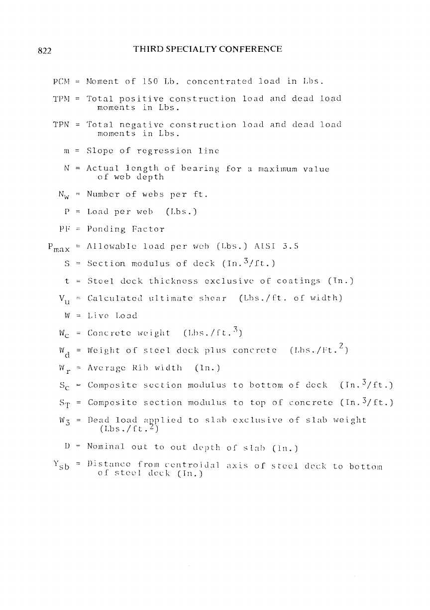
PC:M
TPI>I
TPN
m
N
p
PF
THIRD
SPECIALTY
CONFERENCE
/>lament
of
150
Lb.
concentrated
load
in
Lbs.
Total
positive
construction
load
and
dead
load
moments
in
Lbs.
Total
negative
construction
load
and
dead
load
moments
in
Lbs.
Slope
of
regression
line
Actual
length
of
bearing
for
a
maximum
value
of
web
depth
Number
of
webs
per
ft.
Load
per
web
(Lbs.)
Punding
Factor
Prnax
AlloHable
load
per
\vcb
(Lbs.)
/\lSI
3.5
Section
modulus
of
deck
(Tn.3/ft.)
s
t
Steel
deck
thickness
exclusive
of
coatings
(ln.)
Vu
Calculated
ultimate
shear
(Lhs./ft.
of
width)
W
Live
Load
Concrete
\vcight
(J.hs./ft.
3
)
Weight
of
steel
deck
plus
concrete
(Lhs./H.
2
)
Average
Rib
lvidth
(ln.)
Sc
Composite
section
moLlulus
to
bottom
of
deck
(Tn.
3
/ft.)
ST
Composite
section
modulus
to
top
of
concrete
(Tn.3/ft.)
Dead
load
a~plied
to
slab
exclusive
of
slab
\veight
c
Lb
s . 1 f t .
-)
lJ
Nominal
out
to
out
Llcpth
of
slab
(ln.)
Distance
from
ccntroid:ll
axis
of
o;tecl
deck
to
bottom
of
stcL'l
deck
(Tn.)
