
Operating Instructions
Radar sensor for continuous level
measurement of liquids
VEGAPULS 64
Two-wire 4 … 20 mA/HART
Document ID: 51141

2
Contents
VEGAPULS 64 • Two-wire 4 … 20 mA/HART
51141-EN-210219
Contents
1 About this document ............................................................................................................... 4
1.1 Function ........................................................................................................................... 4
1.2 Target group ..................................................................................................................... 4
1.3 Symbols used................................................................................................................... 4
2 For your safety ......................................................................................................................... 5
2.1 Authorised personnel ....................................................................................................... 5
2.2 Appropriate use ................................................................................................................ 5
2.3 Warning about incorrect use ............................................................................................. 5
2.4 General safety instructions ............................................................................................... 5
2.5 EU conformity ................................................................................................................... 6
2.6 NAMUR recommendations .............................................................................................. 6
2.7 Radio license for Europe .................................................................................................. 6
2.8 Radio license for USA ...................................................................................................... 7
2.9 Radio license for Canada ................................................................................................. 7
2.10 Installation and operation in the USA and Canada ........................................................... 9
2.11 Environmental instructions ............................................................................................... 9
3 Product description ............................................................................................................... 10
3.1 Conguration .................................................................................................................. 10
3.2 Principle of operation...................................................................................................... 11
3.3 Packaging, transport and storage ................................................................................... 11
3.4 Accessories.................................................................................................................... 12
4 Mounting ................................................................................................................................. 14
4.1 General instructions ....................................................................................................... 14
4.2 Mounting versions, plastic horn antenna ........................................................................ 14
4.3 Mounting preparations, mounting strap .......................................................................... 17
4.4 Mounting instructions ..................................................................................................... 18
4.5 Measurement setup - Flow ............................................................................................. 26
5 Connecting to power supply ................................................................................................. 29
5.1 Preparing the connection ............................................................................................... 29
5.2 Connecting ..................................................................................................................... 30
5.3 Wiring plan, single chamber housing.............................................................................. 31
5.4 Wiring plan, double chamber housing ............................................................................ 32
5.5 Wiring plan - version IP66/IP68, 1 bar ............................................................................ 34
5.6 Switch-on phase............................................................................................................. 35
6 Set up with the display and adjustment module ................................................................ 36
6.1 Insert display and adjustment module ............................................................................ 36
6.2 Adjustment system ......................................................................................................... 37
6.3 Measured value indication - Selection of national language ........................................... 38
6.4 Parameter adjustment - Quick setup .............................................................................. 39
6.5 Parameter adjustment - Extended adjustment................................................................ 39
6.6 Saving the parameterisation data ................................................................................... 55
7 Setup with PACTware ............................................................................................................. 56
7.1 Connect the PC .............................................................................................................. 56
7.2 Parameter adjustment with PACTware ............................................................................ 56
7.3 Saving the parameterisation data ................................................................................... 58

3
Contents
VEGAPULS 64 • Two-wire 4 … 20 mA/HART
51141-EN-210219
8 Set up with other systems .................................................................................................... 59
8.1 DD adjustment programs ............................................................................................... 59
8.2 Field Communicator 375, 475 ........................................................................................ 59
9 Diagnosis, asset management and service ........................................................................ 60
9.1 Maintenance .................................................................................................................. 60
9.2 Measured value and event memory ............................................................................... 60
9.3 Asset Management function ........................................................................................... 61
9.4 Rectify faults ................................................................................................................... 64
9.5 Exchanging the electronics module ................................................................................ 68
9.6 Software update ............................................................................................................. 68
9.7 How to proceed if a repair is necessary .......................................................................... 69
10 Dismount................................................................................................................................. 70
10.1 Dismounting steps.......................................................................................................... 70
10.2 Disposal ......................................................................................................................... 70
11 Supplement ............................................................................................................................ 71
11.1 Technical data ................................................................................................................ 71
11.2 Radio astronomy stations ............................................................................................... 84
11.3 Dimensions .................................................................................................................... 84
11.4 Industrial property rights ................................................................................................. 97
11.5 Trademark ...................................................................................................................... 97
Safety instructions for Ex areas
TakenoteoftheExspecicsafetyinstructionsforExapplications.
These instructions are attached as documents to each instrument
with Ex approval and are part of the operating instructions.
Editing status: 2021-02-17

4
1 About this document
VEGAPULS 64 • Two-wire 4 … 20 mA/HART
51141-EN-210219
1 About this document
1.1 Function
This instruction provides all the information you need for mounting,
connection and setup as well as important instructions for mainte-
nance,faultrectication,theexchangeofpartsandthesafetyofthe
user. Please read this information before putting the instrument into
operation and keep this manual accessible in the immediate vicinity
of the device.
1.2 Target group
This operating instructions manual is directed to trained personnel.
Thecontentsofthismanualmustbemadeavailabletothequalied
personnel and implemented.
1.3 Symbols used
Document ID
This symbol on the front page of this instruction refers to the Docu-
ment ID. By entering the Document ID on www.vega.com you will
reach the document download.
Information, note, tip: This symbol indicates helpful additional infor-
mation and tips for successful work.
Note: This symbol indicates notes to prevent failures, malfunctions,
damage to devices or plants.
Caution: Non-observance of the information marked with this symbol
may result in personal injury.
Warning: Non-observance of the information marked with this symbol
may result in serious or fatal personal injury.
Danger: Non-observance of the information marked with this symbol
results in serious or fatal personal injury.
Ex applications
This symbol indicates special instructions for Ex applications.
•
List
The dot set in front indicates a list with no implied sequence.
1 Sequence of actions
Numbers set in front indicate successive steps in a procedure.
Battery disposal
This symbol indicates special information about the disposal of bat-
teries and accumulators.

5
2 For your safety
VEGAPULS 64 • Two-wire 4 … 20 mA/HART
51141-EN-210219
2 For your safety
2.1 Authorised personnel
All operations described in this documentation must be carried out
onlybytrained,qualiedpersonnelauthorisedbytheplantoperator.
During work on and with the device, the required personal protective
equipment must always be worn.
2.2 Appropriate use
VEGAPULS 64 is a sensor for continuous level measurement.
Youcannddetailedinformationabouttheareaofapplicationin
chapter " Product description".
Operational reliability is ensured only if the instrument is properly
usedaccordingtothespecicationsintheoperatinginstructions
manual as well as possible supplementary instructions.
2.3 Warning about incorrect use
Inappropriate or incorrect use of this product can give rise to applica-
tion-specichazards,e.g.vesseloverllthroughincorrectmounting
or adjustment. Damage to property and persons or environmental
contamination can result. Also, the protective characteristics of the
instrument can be impaired.
2.4 General safety instructions
This is a state-of-the-art instrument complying with all prevailing
regulations and directives. The instrument must only be operated in a
technicallyawlessandreliablecondition.Theoperatorisresponsi-
ble for the trouble-free operation of the instrument. When measuring
aggressive or corrosive media that can cause a dangerous situation
if the instrument malfunctions, the operator has to implement suitable
measures to make sure the instrument is functioning properly.
The safety instructions in this operating instructions manual, the na-
tional installation standards as well as the valid safety regulations and
accident prevention rules must be observed by the user.
For safety and warranty reasons, any invasive work on the device
beyond that described in the operating instructions manual may be
carried out only by personnel authorised by the manufacturer. Arbi-
traryconversionsormodicationsareexplicitlyforbidden.Forsafety
reasons,onlytheaccessoryspeciedbythemanufacturermustbe
used.
To avoid any danger, the safety approval markings and safety tips on
the device must also be observed.
The low transmitting power of the radar sensor is far below the inter-
nationally approved limits. No health impairments are to be expected
with intended use. The band range of the measuring frequency can
be found in chapter " Technical data".

6
2 For your safety
VEGAPULS 64 • Two-wire 4 … 20 mA/HART
51141-EN-210219
2.5 EU conformity
ThedevicefullsthelegalrequirementsoftheapplicableEUdirec-
tives.ByaxingtheCEmarking,weconrmtheconformityofthe
instrument with these directives.
The EU conformity declaration can be found on our homepage.
2.6 NAMUR recommendations
NAMUR is the automation technology user association in the process
industry in Germany. The published NAMUR recommendations are
acceptedasthestandardineldinstrumentation.
ThedevicefullstherequirementsofthefollowingNAMURrecom-
mendations:
•
NE 21 – Electromagnetic compatibility of equipment
•
NE 43 – Signal level for fault information from measuring transduc-
ers
•
NE53–Compatibilityofelddevicesanddisplay/adjustment
components
•
NE107–Self-monitoringanddiagnosisofelddevices
For further information see www.namur.de.
2.7 Radio license for Europe
The instrument was tested according to the latest issue of the follow-
ingharmonizedstandards:
•
EN 302372 - Tank Level Probing Radar
•
EN 302729 - Level Probing Radar
It is hence approved for use inside and outside closed vessels in
countries of the EU.
Use is also approved in EFTA countries, provided the respective
standards have been implemented.
For operation inside of closed vessels, points a to f in annex E of
EN302372mustbefullled.
For operation outside of closed vessels, the following conditions must
befullled:
•
The instrument must be stationary mounted and the antenna
directed vertically downward
•
The instrument may only be used outside closed vessels in the
version with G1½ or 1½ NPT thread with integrated horn antenna.
•
The mounting location must be at least 4 km away from radio
astronomy stations, unless special permission was granted by the
responsible national approval authority
•
When installed within 4 to 40 km of a radio astronomy station,
the instrument must not be mounted higher than 15 m above the
ground.
A list of the respective radio astronomy stations can be found in chap-
ter " Appendix" of the operating instructions.

7
2 For your safety
VEGAPULS 64 • Two-wire 4 … 20 mA/HART
51141-EN-210219
2.8 Radio license for USA
This approval is only valid for USA. Hence the following text is only
available in the English language:
This device complies with Part 15 of the FCC Rules. Operation is
subject to the following two conditions:
•
This device may not cause interference, and
•
This device must accept any interference, including interference
that may cause undesired operation of the device
This device is approved for unrestricted use only inside closed, sta-
tionaryvesselsmadeofmetal,reinforcedberglassorconcrete.
For operation outside of closed vessels, the following conditions must
befullled:
•
This device shall be installed and maintained to ensure a verti-
cally downward orientation of the transmit antenna's main beam.
Furthermore, the use of any mechanism that does not allow the
main beam of the transmitter to be mounted vertically downward is
prohibited.
•
Operation of the instrument is only permitted with thread G1½ or
1½ NPT with integrated horn antenna.
•
Thisdeviceshallbeinstalledonlyatxedlocations.TheLPR
device shall not operate while being moved or while inside a mov-
ing container.
•
Hand-held applications are prohibited.
•
Marketing to residential consumers is prohibited.
Changesormodicationsnotexpresslyapprovedbythemanufac-
turer could void the user’s authority to operate this equipment.
2.9 Radio license for Canada
This approval is only valid for Canada. Hence the following texts are
only available in the English/French language:
This device complies with Industry Canada's license-exempt RSS
standard(s). Operation is subject to the following conditions:
•
This device may not cause interference, and
•
This device must accept any interference, including interference
that may cause undesired operation of the device
This device has been approved for both closed containers and open-
air environments with the following limitations:
•
ClosedContainers:Forinstallationsutilizingatiltduringinstalla-
tion: This device is limited to installation in a completely enclosed
containermadeofmetal,reinforcedberglassorconcretetopre-
vent RF emissions, which can otherwise interfere with aeronauti-
cal navigation, the maximum approved tilt angel is 10°.
•
Open Air Environment: For operation outside of closed vessels,
thefollowingconditionmustbefullled:Thisdeviceshallbe
installed and maintained to ensure a vertically downward orienta-
tion of the transmit antenna's main beam. Furthermore, the use of

8
2 For your safety
VEGAPULS 64 • Two-wire 4 … 20 mA/HART
51141-EN-210219
any mechanism that does not allow the main beam of the transmit-
ter to be mounted vertically downward is prohibited.
•
Operation of the instrument outside of closed vessels is only per-
mitted with G1½ or 1½ NPT with integrated horn antenna.
•
The installation of the LPR/TLPR device shall be done by trained
installers, in strict compliance with the manufacturer's instructions.
•
Thisdeviceshallbeinstalledonlyatxedlocations.TheLPR
device shall not operate while being moved or while inside a mov-
ing container.
•
Hand-held applications are prohibited.
•
Marketing to residential consumers is prohibited.
•
The use of this device is on a "no-interference, no-protection"
basis. That is, the user shall accept operations of high-powered
radar in the same frequency band which may interfere with or
damage this device.
•
However, devices found to interfere with primary licensing opera-
tions will be required to be removed at the user's expense.
•
The installer/user of this device shall ensure that it is at least 10 km
from the Dominion Astrophysical Radio Observatory (DRAO) near
Penticton, British Columbia. The coordinates of the DRAO are
latitude49°19′15″Nandlongitude119°37′12″W.Fordevicesnot
meeting this 10 km separation (e.g., those in the Okanagan Valley,
British Columbia,) the installer/user must coordinate with, and
obtain the written concurrence of, the Director of the DRAO before
the equipment can be installed or operated. The Director of the
DRAO may be contacted at 250-497-2300 (tel.)or 250-497-2355
(fax). (Alternatively, the Manager, Regulatory Standards, Industry
Canada, may be contacted.)
Le présent appareil est conforme aux CNR d’Industrie Canada ap-
plicables aux appareils radio exempts de licence. L’exploitation est
autorisée aux conditions suivantes :
•
L’appareil ne doit pas produire de brouillage; et
•
L’utilisateur de l’appareil doit accepter tout brouillage radioélect-
rique subi, même si le brouillage est susceptible d’en compromet-
tre le fonctionnement.
Cet appareil est homologué pour une utilisation dans les cuves fer-
mées et les environnements ouverts avec les restrictions suivantes :
•
Cuves fermées : Pour les installations impliquant une inclinaison
lors de l'installation : cet appareil ne doit être installé que dans une
cuve totalement fermée en métal ou en béton, pour empêcher les
émissions RF susceptibles d'interférer avec la navigation aéronau-
tique. L'angle d'inclinaison maximum autorisé est de 10°.
•
Environnement ouvert : Pour l'utilisation hors des cuves fermées,
la condition suivante doit être remplie : L'appareil doit être installé
et entretenu de manière à garantir une orientation verticale vers
le bas du faisceau principal de l’antenne émettrice. De plus,
l’utilisation de tout mécanisme ne permettant pas l’orientation ver-
ticale vers le bas du faisceau principal de l’émetteur est interdite
•
Il est uniquement autorisé d'utiliser la version d'appareil avec le
letageG1½ou1½NPTenenvironnementsouvertes.

9
2 For your safety
VEGAPULS 64 • Two-wire 4 … 20 mA/HART
51141-EN-210219
•
L’installationd’undispositifLPRouTLPRdoitêtreeectuée
pardesinstallateursqualiés,enpleineconformitéavecles
instructions du fabricant.
•
Cetappareilnedoitêtreinstalléqu'àdesemplacementsxes.
L’appareil LPR ne doit pas être utilisé pendant qu’il est en train
d’être déplacé ou se trouve dans un conteneur en mouvement.
•
Les applications portables sont interdites.
•
La vente à des particuliers est interdite
•
Ce dispositif ne peut être exploité qu'en régime de non-brouillage
et de non-protection, c'est-à-dire que l'utilisateur doit accepter que
des radars de haute puissance de la même bande de fréquences
puissent brouiller ce dispositif ou même l'endommager.
•
D'autre part, les capteurs de niveau qui perturbent une exploita-
tion autorisée par licence de fonctionnement principal doivent être
enlevés aux frais de leur utilisateur.
•
La personne qui installe/utilise ce capteur de niveau doit s'assurer
qu'il se trouve à au moins 10 km de l'Observatoire fédéral de
radioastrophysique (OFR) de Penticton en Colombie-Britannique.
Lescoordonnéesdel'OFRsont:latitudeN49°19′15″,longitude
O119°37′12″.Lapersonnequiinstalle/utiliseundispositifne
pouvant respecter cette distance de 10 km (p. ex. dans la vallée
de l'Okanagan [Colombie-Britannique]) doit se concerter avec le
directeurdel'OFRand’obtenirdesapartuneautorisationécrite
avant que l'équipement ne puisse être installé ou mis en marche.
Le directeur de l'OFR peut être contacté au 250-497-2300 (tél.) ou
au 250-497-2355 (fax). (Le Directeur des Normes réglementaires
d'Industrie Canada peut également être contacté).
2.10 Installation and operation in the USA and
Canada
This information is only valid for USA and Canada. Hence the follow-
ing text is only available in the English language.
Installations in the US shall comply with the relevant requirements of
the National Electrical Code (ANSI/NFPA 70).
Installations in Canada shall comply with the relevant requirements of
the Canadian Electrical Code
A Class 2 power supply unit has to be used for the installation in the
USA and Canada.
2.11 Environmental instructions
Protection of the environment is one of our most important duties.
That is why we have introduced an environment management system
with the goal of continuously improving company environmental pro-
tection.Theenvironmentmanagementsystemiscertiedaccording
to DIN EN ISO 14001.
Pleasehelpusfullthisobligationbyobservingtheenvironmental
instructions in this manual:
•
Chapter " Packaging, transport and storage"
•
Chapter " Disposal"

10
3 Product description
VEGAPULS 64 • Two-wire 4 … 20 mA/HART
51141-EN-210219
3 Product description
3.1 Conguration
The scope of delivery encompasses:
•
VEGAPULS 64 radar sensor
•
Discsprings(angeversionwithencapsulatedantennasystem)
1)
•
Optional accessory
The further scope of delivery encompasses:
•
Documentation
– Quick setup guide VEGAPULS 64
– Instructions for optional instrument features
– Ex-specic"Safety instructions" (with Ex versions)
– Ifnecessary,furthercerticates
Information:
Optional instrument features are also described in this operating
instructions manual. The respective scope of delivery results from the
orderspecication.
This operating instructions manual applies to the following instrument
versions:
•
Hardware version from 1.0.3
•
Software version from 1.3.3
Thetypelabelcontainsthemostimportantdataforidenticationand
use of the instrument:
6
5
4
3
2
1
Fig. 1: Layout of the type label (example)
1 Instrument type, product code
2 Field for approvals
3 Technical data
4 Data matrix code for VEGA Tools app
5 Reminder to observe the instrument documentation
The type label contains the serial number of the instrument. With it
youcanndthefollowinginstrumentdataonourhomepage:
Scope of delivery
Scope of this operating
instructions
Type label
Serial number - Instru-
ment search
1)
Use see chapter "Mounting instructions, sealing to the process"

11
3 Product description
VEGAPULS 64 • Two-wire 4 … 20 mA/HART
51141-EN-210219
•
Product code (HTML)
•
Delivery date (HTML)
•
Order-specicinstrumentfeatures(HTML)
•
Operating instructions and quick setup guide at the time of ship-
ment (PDF)
•
Order-specicsensordataforanelectronicsexchange(XML)
•
Testcerticate(PDF)-optional
Move to " www.vega.com"andenterinthesearcheldtheserial
number of your instrument.
Alternatively, you can access the data via your smartphone:
•
Download the VEGA Tools app from the " Apple App Store" or the
" Google Play Store"
•
Scan the DataMatrix code on the type label of the instrument or
•
Enter the serial number manually in the app
3.2 Principle of operation
VEGAPULS 64 is a radar sensor for continuous level measurement of
liquids.
Thesmallprocessttingsoerparticularadvantagesinsmalltanksor
tight mounting spaces. The very good signal focusing ensures the use
in vessels with many installations such as stirrers and heating spirals.
TheVEGAPULS64isavailablewithdierentantennasystems:
1 2 3
Fig. 2: Antenna systems VEGAPULS 64
1 Thread with integrated horn antenna
2 Plastic horn antenna
3 Flange with encapsulated antenna system
The instrument emits a continuous, frequency-modulated radar signal
throughitsantenna.Theemittedsignalisreectedbythemedium
andreceivedbytheantennaasanechowithmodiedfrequency.The
frequency change is proportional to the distance and is converted into
the level.
3.3 Packaging, transport and storage
Your instrument was protected by packaging during transport. Its
capacity to handle normal loads during transport is assured by a test
based on ISO 4180.
Application area
Functional principle
Packaging

12
3 Product description
VEGAPULS 64 • Two-wire 4 … 20 mA/HART
51141-EN-210219
The packaging consists of environment-friendly, recyclable card-
board. For special versions, PE foam or PE foil is also used. Dispose
of the packaging material via specialised recycling companies.
Transport must be carried out in due consideration of the notes on the
transport packaging. Nonobservance of these instructions can cause
damage to the device.
The delivery must be checked for completeness and possible transit
damage immediately at receipt. Ascertained transit damage or con-
cealed defects must be appropriately dealt with.
Up to the time of installation, the packages must be left closed and
stored according to the orientation and storage markings on the
outside.
Unless otherwise indicated, the packages must be stored only under
the following conditions:
•
Not in the open
•
Dry and dust free
•
Not exposed to corrosive media
•
Protected against solar radiation
•
Avoiding mechanical shock and vibration
•
Storage and transport temperature see chapter " Supplement -
Technical data - Ambient conditions"
•
Relative humidity 20 … 85 %
With instrument weights of more than 18 kg (39.68 lbs) suitable and
approved equipment must be used for lifting and carrying.
3.4 Accessories
The instructions for the listed accessories can be found in the down-
load area on our homepage.
The display and adjustment module is used for measured value indi-
cation, adjustment and diagnosis.
The integrated Bluetooth module (optional) enables wireless adjust-
ment via standard adjustment devices.
The interface adapter VEGACONNECT enables the connection of
communication-capable instruments to the USB interface of a PC.
The VEGADIS 81 is an external display and adjustment unit for VEGA
plics
®
sensors.
The VEGADIS adapter is an accessory part for sensors with double
chamber housings. It enables the connection of VEGADIS 81 to the
sensor housing via an M12 x 1 plug.
Transport
Transport inspection
Storage
Storage and transport
temperature
Lifting and carrying
PLICSCOM
VEGACONNECT
VEGADIS 81
VEGADIS adapter

13
3 Product description
VEGAPULS 64 • Two-wire 4 … 20 mA/HART
51141-EN-210219
VEGADIS 82 is suitable for measured value indication and adjustment
of sensors with HART protocol. It is looped into the 4 … 20 mA/HART
signal cable.
The PLICSMOBILE T81 is an external GSM/GPRS/UMTS radio unit
for transmission of measured values and for remote parameter adjust-
ment of HART sensors.
PLICSMOBILE 81 is an internal GSM/GPRS/UMTS radio unit for
HART sensors for transmitting measured values and for remote
parameterization.
The protective cover protects the sensor housing against soiling and
intense heat from solar radiation.
Screwedangesareavailableindierentversionsaccordingtothe
following standards: DIN 2501, EN 1092-1, BS 10, ASME B 16.5,
JIS B 2210-1984, GOST 12821-80.
Welded sockets are used to connect the sensors to the process.
Threaded adapters are used for adaptation of the sensor with
threadedttingG¾orG1½toexistingweldedsockets.
VEGADIS 82
PLICSMOBILE T81
PLICSMOBILE 81
Protective cover
Flanges
Welded sockets and
adapters

14
4 Mounting
VEGAPULS 64 • Two-wire 4 … 20 mA/HART
51141-EN-210219
4 Mounting
4.1 General instructions
Protect your instrument against moisture ingress through the following
measures:
•
Use a suitable connection cable (see chapter " Connecting to
power supply")
•
Tighten the cable gland or plug connector
•
Lead the connection cable downward in front of the cable entry or
plug connector
This applies mainly to outdoor installations, in areas where high
humidity is expected (e.g. through cleaning processes) and on cooled
or heated vessels.
Note:
Make sure that during installation or maintenance no moisture or dirt
can get inside the instrument.
To maintain the housing protection, make sure that the housing lid is
closed during operation and locked, if necessary.
Note:
For safety reasons, the instrument must only be operated within the
permissibleprocessconditions.Youcannddetailedinformationon
the process conditions in chapter " Technical data" of the operating
instructions or on the type label.
Hence make sure before mounting that all parts of the instrument ex-
posed to the process are suitable for the existing process conditions.
These are mainly:
•
Active measuring component
•
Processtting
•
Process seal
Process conditions in particular are:
•
Process pressure
•
Process temperature
•
Chemical properties of the medium
•
Abrasionandmechanicalinuences
As a standard feature, the VEGAPULS 64 is separate from the pro-
cess through its plastic antenna encapsulation.
Optionally, the instrument is available with a Second Line of Defense
(SLOD), a second process separation. It is located as gas-tight
leadthrough between the process component and the electronics.
This means additional safety against penetration of the medium fron
the process into the instrument.
4.2 Mounting versions, plastic horn antenna
The optional mounting strap allows simple mounting of the instrument
on a wall, ceiling or boom. Especially in the case of open vessels, this
Protection against mois-
ture
Process conditions
Second Line of Defense
Mounting strap

15
4 Mounting
VEGAPULS 64 • Two-wire 4 … 20 mA/HART
51141-EN-210219
isasimpleandeectivewaytoalignthesensortothesurfaceofthe
bulk solid material.
The following versions are available:
•
Length 300 mm
•
Length 170 mm
The instrument is normally mounted vertically with a bracket on the
ceiling.
This allows swivelling the sensor up to 180° for optimal orientation
and rotating for optimal connection.
Fig. 3: Ceiling mounting via the mounting strap with length 300 mm
Asanalternativethestrapmountingiscarriedouthorizontallyor
obliquely.
> 200 mm
(7.87")
Fig. 4: Wall mounting horizontally via the mounting strap with length 170 mm
Mounting strap - Ceiling
mounting
Mounting strap - Wall
mounting

16
4 Mounting
VEGAPULS 64 • Two-wire 4 … 20 mA/HART
51141-EN-210219
Fig. 5: Wall mounting with inclined wall via the mounting strap with length
300 mm
Twoversionsareavailableformountingtheinstrumentonanozzle:
•
Combicompressionange
•
Adapterange
Combicompressionange
Thecombicompressionangeissuitablefordierentvesselanges
DN 80, ASME 3" and JIS 80. It comes not sealed against the radar
sensorandcanthusonlybeusedunpressurized.Itcanberetrotted
oninstrumentswithsinglechamberhousing,retrottingtoadouble
chamber housing is not possible.
1
Fig. 6: Combi compression ange
1 Combi compression ange
Adapterange
TheadapterangeisavailablefromDN100,ASME4"andJIS100.It
is permanently connected with the radar sensor and sealed.
Flange

17
4 Mounting
VEGAPULS 64 • Two-wire 4 … 20 mA/HART
51141-EN-210219
3
1
2
Fig. 7: Adapter ange
1 Connection screw
2 Adapter ange
3 Process seal
4.3 Mounting preparations, mounting strap
The mounting strap is supplied unassembled (optionally) and must be
screwed to the sensor before setup with three hexagon socket screws
M5 x 10 and spring washers. Max. torque, see chapter " Technical
data".Requiredtools:Allenwrenchsize4.
Therearetwodierentvariantsofscrewingthestraptothesensor,
see following illustration:
1 2
Fig. 8: Mounting strap for screwing to the sensor
1 For angle of inclination in steps
2 For angle of inclination, innitely variable
Depending on the selected variant, the sensor can be rotated in the
strap:
•
Single chamber housing
– Angle of inclination in three steps 0°, 90° and 180°
– Angleofinclination180°,innitelyvariable
•
Double chamber housing
– Angle of inclination in two steps 0° and 90°
– Angleofinclination90°,innitelyvariable

18
4 Mounting
VEGAPULS 64 • Two-wire 4 … 20 mA/HART
51141-EN-210219
Fig. 9: Adjustment of the angle of inclination
Fig. 10: Turning by fastening in the centre
4.4 Mounting instructions
Radar sensors for level measurement emit electromagnetic waves.
Thepolarizationisthedirectionoftheelectricalcomponentofthese
waves.
Thepolarizationdirectionismarkedbyanoseonthehousing,see
following drawing:
1
Fig. 11: Position of the polarisation
1 Nose for marking the direction of polarisation
Note:
Whenthehousingisrotated,thedirectionofpolarizationchanges
andhencetheinuenceofthefalseechoonthemeasuredvalue.
Please keep this in mind when mounting or making changes later.
When mounting the device, keep a distance of at least 200 mm
(7.874 in) from the vessel wall. If the device is installed in the center
of dished or round vessel tops, multiple echoes can arise. However,
Polarisation
Installation position

19
4 Mounting
VEGAPULS 64 • Two-wire 4 … 20 mA/HART
51141-EN-210219
these can be suppressed by an appropriate adjustment (see chapter
" Setup").
If you cannot maintain this distance, you should carry out a false
signal suppression during setup. This applies particularly if buildup on
the vessel wall is expected. In such cases, we recommend repeating
the false signal suppression at a later date with existing buildup.
> 200 mm
(7.87
")
Fig. 12: Mounting of the radar sensor on round vessel tops
In vessels with conical bottom it can be advantageous to mount the
device in the centre of the vessel, as measurement is then possible
down to the bottom.
Fig. 13: Mounting of the radar sensor on vessels with conical bottom
The measuring range of VEGAPULS 64 begins physically at the end
of the antenna. The min./max. adjustment, however, begins at the
referenceplane.Thereferenceplaneisdierentdependingonthe
sensor version.
•
Plastic horn antenna: The reference plane is the sealing surface
on the lower edge
•
Thread with integrated horn antenna: The reference plane is
the sealing surface at the bottom of the hexagon
•
Flange with encapsulated antenna system: The reference
planeistheloweredgeoftheangeplating
•
Hygienicttings: The reference plane is the highest contact point
betweensensorprocessttingandweldedsocket
Reference plane

20
4 Mounting
VEGAPULS 64 • Two-wire 4 … 20 mA/HART
51141-EN-210219
The following graphic shows the position of the reference plane with
dierentsensorversions.
2
1
1
1
1
3
4 5
Fig. 14: Position of the reference plane
1 Reference plane
2 Plastic horn antenna
3 Threaded ttings
4 Flange connections
5 Hygienic ttings
Donotmounttheinstrumentsinorabovethellingstream.Makesure
thatyoudetectthemediumsurface,nottheinowingproduct.
Fig. 15: Mounting of the radar sensor with inowing medium
Fornozzlemounting,thenozzleshouldbeasshortaspossibleand
itsendrounded.Thisreducesfalsereectionsfromthenozzle.
With threaded connection, the antenna end should protrude at least
5mm(0.2in)outofthenozzle.
ca. 5 mm
1 2 3
Fig. 16: Recommended socket mounting with dierent versions of VEGAPULS
64
1 Thread with integrated horn antenna
2 Plastic horn antenna
3 Flange with encapsulated antenna system
Inowingmedium
Nozzle

21
4 Mounting
VEGAPULS 64 • Two-wire 4 … 20 mA/HART
51141-EN-210219
Ifthereectivepropertiesofthemediumaregood,youcanmount
VEGAPULS 64 on sockets longer than the antenna. The socket end
should be smooth and burr-free, if possible also rounded.
Note:
Whenmountingonlongernozzles,werecommendcarryingouta
false signal suppression (see chapter " Parameter adjustment").
Youwillndrecommendedvaluesforsocketheightsinthefollowing
illustration or the tables. The values come from typical applications.
Deviating from the proposed dimensions, also longer sockets are
possible, however the local conditions must be taken into account.
1 2 3
d
h
d
h
d
h
Fig. 17: Socket mounting with deviating socket dimensions with dierent ver-
sions of VEGAPULS 64
1 Thread with integrated horn antenna
2 Plastic horn antenna
3 Flange with encapsulated antenna system
Thread with integrated horn antenna
Socket diameter d Socket length h
40 mm 1½" ≤150mm ≤5.9in
50 mm 2" ≤200mm ≤7.9in
80 mm 3" ≤300mm ≤11.8in
100 mm 4" ≤400mm ≤15.8in
150 mm 6" ≤600mm ≤23.6in
Plastic horn antenna
Socket diameter d Socket length h
80 mm 3" ≤400mm ≤15.8in
100 mm 4" ≤500mm ≤19.7in
150 mm 6" ≤800mm ≤31.5in

22
4 Mounting
VEGAPULS 64 • Two-wire 4 … 20 mA/HART
51141-EN-210219
Flange with encapsulated antenna system
Socket diameter d Socket length h
50 mm 2" ≤200mm ≤7.9in
80 mm 3" ≤400mm ≤15.8in
100 mm 4" ≤500mm ≤19.7in
150 mm 6" ≤800mm ≤31.5in
TheVEGAPULS64withangeandencapsulatedantennasystem,
the PTFE washer of the antenna encapsulation serves also as pro-
cess seal.
2
1
Fig. 18: VEGAPULS 64 with ange and encapsulated antenna system
1 PTFE washer
2 Antenna encapsulation
However,PTFE-platedangeshaveapreloadlossovertimeathigh
temperature changes.
Note:
Therefore, use disc springs to compensate for this preload loss during
mounting. They are included in the scope of delivery of the instrument
andareintendedfortheangescrews.
Tosealeectively,thefollowingrequirementsmustbefullled:
1. Makesurethenumberofangescrewscorrespondstothenum-
berofangeholes
2. Use of disc springs as previously described
1
2
Fig. 19: Use of disc springs
1 Disc spring
2 Sealing surface
Sealing to the process

23
4 Mounting
VEGAPULS 64 • Two-wire 4 … 20 mA/HART
51141-EN-210219
3. Tighten screws with the necessary torque (see chapter " Techni-
cal data", " Torques")
2)
Note:
We recommend re-tightening the screws at regular intervals, depend-
ing on process pressure and temperature. Recommended torque, see
chapter " Technical data", " Torques".
The PTFE washer in 8 mm version can be exchanged by the user in
case of wear or damage.
Proceed as follows while dismounting:
1. Dismount and clean the instrument, note chapters " Dismounting
steps" and " Maintenance"
2. Unscrew and remove the PTFE disc by hand, protecting the
thread against dirt.
Fig. 20: VEGAPULS 64 - Loosening the PTFE washer
3. Remove the sealing and clean the sealing groove
4. Insert the supplied new sealing, place the PTFE washer onto the
thread and tighten it manually
5. Mountthesensor,tightentheangescrews(torqueseechapter"
Technical data", " Torques")
Note:
We recommend re-tightening the screws at regular intervals, depend-
ing on process pressure and temperature. Recommended torque, see
chapter " Technical data", " Torques".
PTFE threaded adapters are available for VEGAPULS 64 with thread
G1½ or 1½ NPT. Due to this, only PTFE is in contact with the medium.
Mount the PTFE threaded adapter in the following way:
Exchange,angeplating
Mounting, PTFE threaded
adapter
2)
Thetorquesspeciedinthetechnicaldataonlyapplytotheplatingshown
here in the area of the sealing surface. For plating up to the outer diameter,
the values are for orientation only; the torque values actually required are
application-specic.

24
4 Mounting
VEGAPULS 64 • Two-wire 4 … 20 mA/HART
51141-EN-210219
1
3
2
4
5
*$
*
*$
*
6:
6:
Fig. 21: VEGAPULS 64 with PTFE threaded adapter
1 Sensor
2 O-ring seal (sensor side)
3 PTFE threaded adapter
4 Flat seal (process side)
5 Welded socket
1. RemoveexistingKlingersilatsealonthethreadofVEGAPULS
64
2. Insert the supplied O-ring seal (1) into the threaded adapter
3. Placethesuppliedatseal(4)ontothethreadoftheadapter
Note:
ForthethreadedadapterinNPTversion,thereisnoatsealrequired
on the process side.
4. Screw the threaded adapter on the hexagon into the welded
socket. Torque see chapter " Technical data"
5. Screw VEGAPULS 64 on the hexagon into the threaded adapter.
Torque see chapter " Technical data"
Instruments for a temperature range up to 200 °C have a spacer
fortemperaturedecouplingbetweenprocessttingandelectronics
housing.
Note:
The spacer may only be incorporated up to a maximum of 40 mm into
the vessel insulation. Only then is a reliable temperature decoupling
guaranteed.
Mounting in the vessel
insulation

25
4 Mounting
VEGAPULS 64 • Two-wire 4 … 20 mA/HART
51141-EN-210219
max. 40 mm
(1.57")
1
2
3
Fig. 22: Mounting the instrument on insulated vessels.
1 Electronics housing
2 Spacer
3 Vessel insulation
The mounting location of the radar sensor should be a place where no
otherequipmentorxturescrossthepathoftheradarsignals.
Vessel installations, such as e.g. ladders, limit switches, heating spi-
rals, struts, etc., can cause false echoes and impair the useful echo.
Make sure when planning your measuring point that the radar sensor
has a " clear view" to the measured product.
In case of existing vessel installations, a false signal suppression
should be carried out during setup.
If large vessel installations such as struts or supports cause false
echoes, these can be attenuated through supplementary measures.
Small,inclinedsheetmetalbaesabovetheinstallations"scatter"
theradarsignalsandpreventdirectinterferingreections.
Fig. 23: Cover at, large-area proles with deectors
In liquids, direct the device as perpendicular as possible to the me-
dium surface to achieve optimum measurement results.
Vessel installations
Orientation

26
4 Mounting
VEGAPULS 64 • Two-wire 4 … 20 mA/HART
51141-EN-210219
Fig. 24: Alignment in liquids
If there are agitators in the vessel, a false signal suppression should
be carried out with the agitators in motion. This ensures that the
interferingreectionsfromtheagitatorsaresavedwiththebladesin
dierentpositions.
Fig. 25: Agitators
Throughtheactionoflling,stirringandotherprocessesinthevessel,
compact foams which considerably damp the emitted signals may
form on the medium surface.
If foams lead to measurement errors, you should use the biggest pos-
sible radar antennas or sensors with guided radar.
4.5 Measurement setup - Flow
In general, the following must be observed while mounting the device:
•
Mounting the sensor on the upstream or inlet side
•
Installationinthecentreoftheumeandverticaltotheliquid
surface
•
DistancetotheoverfalloriceorVenturiume
•
Min. distance to the max. height of damming for optimum accu-
racy: 250 mm (9.843 in)
3)
Agitators
Foam generation
Mounting
3)
At smaller distances the measuring accuracy is reduced, see "Technical
data".

27
4 Mounting
VEGAPULS 64 • Two-wire 4 … 20 mA/HART
51141-EN-210219
Everyumegeneratesadierentlevelofbackwaterdependingonits
typeandversion.Thespecicationsofthefollowingumesareavail-
able in the instrument:
Predenedcurves
Aowmeasurementwiththesestandardcurvesisveryeasytoset
up,asnodimensionalinformationoftheumeisrequired.
•
Palmer-Bowlusume(Q=kxh
1.86
)
•
Venturi,trapezoidalweir,rectangularume(Q=kxh
1.5
)
•
V-Notch,triangularoverfall(Q=kxh
2.5
)
Dimensions (ISO standard)
Whenselectingthesecurves,thedimensionsoftheumemustbe
known and entered via the assistant. As a result, the accuracy of the
owmeasurementishigherthanwiththespeciedcurves.
•
Rectangularume(ISO4359)
•
Trapezoidalume(ISO4359)
•
U-shapedume(ISO4359)
•
Triangular overfall thin-walled (ISO 1438)
•
Rectangularumethin-walled(ISO1438)
•
Rectangular weir broad crown (ISO 3846)
Flow formula
Iftheowformulaofyourumeisknown,youshouldselectthisop-
tion,astheaccuracyoftheowmeasurementishighesthere.
•
Flowformula:Q=kxh
exp
Manufacturerdenition
IfyouuseaParshallumefromthemanufacturerISCO,thisoption
mustbeselected.Thisgivesyouahighaccuracyofowmeasure-
mentwitheasyconguration.
Alternatively, you can also take over Q/h table values provided by the
manufacturer here.
•
ISCOParshallume
•
Q/htable(assignmentofheightwithcorrespondingowinatable)
Detailed project planning data can be found at the channel manufac-
turers and in the technical literature.
Thefollowingexamplesserveasanoverviewforowmeasurement.
Flume

28
4 Mounting
VEGAPULS 64 • Two-wire 4 … 20 mA/HART
51141-EN-210219
h
max
≥ 2 x h
max
90°
4
3 ... 4 h
max
90°
2 3
1
Fig. 26: Flow measurement with rectangular ume: h
max.
= max. lling of the
rectangular ume
1 Overfall orice (side view)
2 Upstream water
3 Tailwater
4 Overfall orice (view from tailwater)
2
3 ... 4 x h
max
90°
h
max
1
B
Fig. 27: Flow measurement with Khafagi-Venturi ume: h
max.
= max. lling of the
ume; B = tightest constriction in the ume
1 Position sensor
2 Venturi ume
Rectangular overfall
Khafagi-Venturiume

29
5 Connecting to power supply
VEGAPULS 64 • Two-wire 4 … 20 mA/HART
51141-EN-210219
5 Connecting to power supply
5.1 Preparing the connection
Always keep in mind the following safety instructions:
•
Carryoutelectricalconnectionbytrained,qualiedpersonnel
authorised by the plant operator
•
If overvoltage surges are expected, overvoltage arresters should
be installed
Warning:
Onlyconnectordisconnectinde-energizedstate.
Power supply and current signal are carried on the same two-wire
cable.Theoperatingvoltagecandierdependingontheinstrument
version.
Thedataforpowersupplyarespeciedinchapter"Technical data".
Provide a reliable separation between the supply circuit and the
mains circuits according to DIN EN 61140 VDE 0140-1.
Power the instrument via an energy-limited circuit acc. to IEC 61010-
1, e.g. via Class 2 power supply unit.
Keepinmindthefollowingadditionalfactorsthatinuencetheoperat-
ing voltage:
•
Lower output voltage of the power supply unit under nominal load
(e.g. with a sensor current of 20.5 mA or 22 mA in case of fault)
•
Inuenceofadditionalinstrumentsinthecircuit(seeloadvaluesin
chapter " Technical data")
The instrument is connected with standard two-wire cable without
shielding. If electromagnetic interference is expected which is above
the test values of EN 61326-1 for industrial areas, shielded cable
should be used.
Use cable with round cross section for instruments with housing and
cable gland. Use a cable gland suitable for the cable diameter to
ensurethesealeectofthecablegland(IPprotectionrating).
Shielded cable generally necessary in HART multidrop mode.
Metric threads
In the case of instrument housings with metric thread, the cable
glands are screwed in at the factory. They are sealed with plastic
plugs as transport protection.
Note:
You have to remove these plugs before electrical connection.
NPT thread
In the case of instrument housings with self-sealing NPT threads, it is
not possible to have the cable entries screwed in at the factory. The
free openings for the cable glands are therefore covered with red dust
protection caps as transport protection.
Safety instructions
Voltage supply
Connection cable
Cable glands

30
5 Connecting to power supply
VEGAPULS 64 • Two-wire 4 … 20 mA/HART
51141-EN-210219
Note:
Prior to setup you have to replace these protective caps with ap-
proved cable glands or close the openings with suitable blind plugs.
On plastic housings, the NPT cable gland or the Conduit steel tube
must be screwed into the threaded insert without grease.
Max. torque for all housings, see chapter " Technical data".
If shielded cable is required, the cable screening must be connected
on both ends to ground potential. In the sensor, the cable screening
is connected directly to the internal ground terminal. The ground ter-
minal on the outside of the housing must be connected to the ground
potential (low impedance).
In Ex systems, the grounding is carried out according to the installa-
tion regulations.
In electroplating plants as well as plants for cathodic corrosion protec-
tionitmustbetakenintoaccountthatsignicantpotentialdierences
exist. This can lead to unacceptably high currents in the cable screen
if it is grounded at both ends.
Information:
Themetallicpartsoftheinstrument(processtting,sensor,concen-
tric tube, etc.) are connected with the internal and external ground
terminal on the housing. This connection exists either directly via
the conductive metallic parts or, in case of instruments with external
electronics, via the screen of the special connection cable.
Youcanndspecicationsonthepotentialconnectionsinsidethe
instrument in chapter " Technical data".
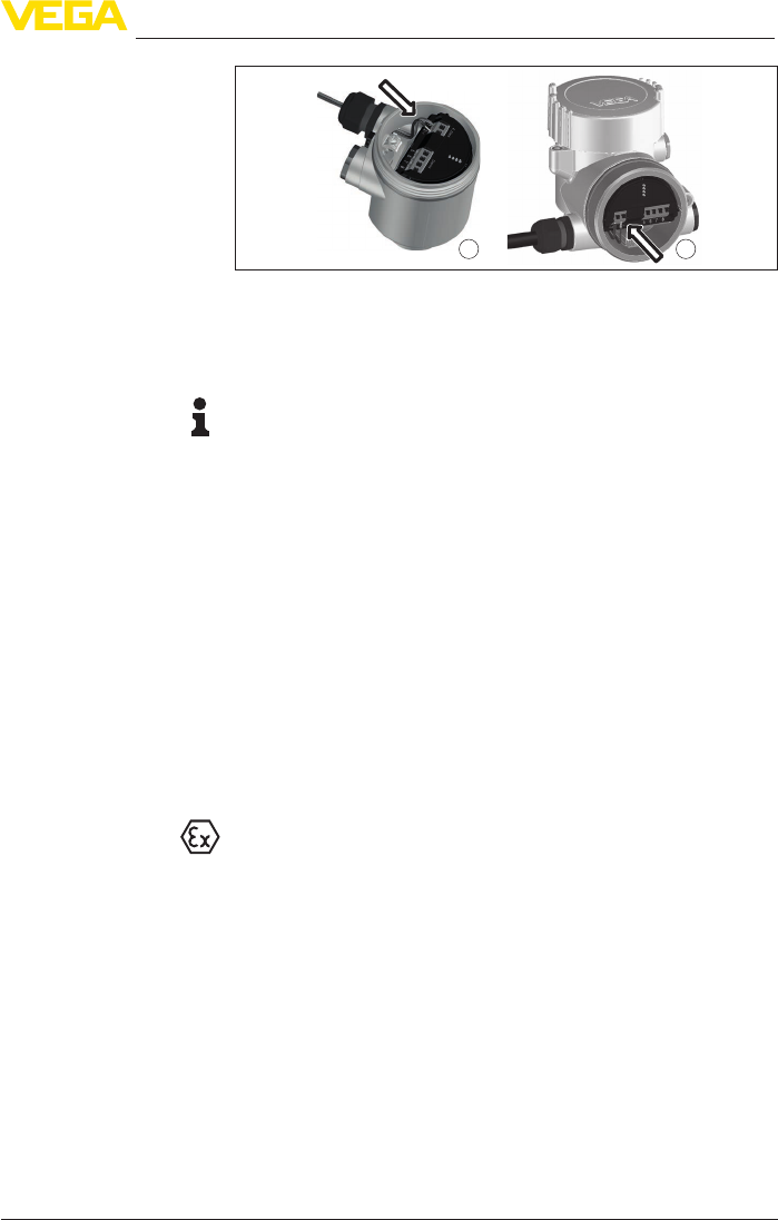
5.2 Connecting
The voltage supply and signal output are connected via the spring-
loaded terminals in the housing.
Connection to the display and adjustment module or to the interface
adapter is carried out via contact pins in the housing.
Information:
The terminal block is pluggable and can be removed from the
electronics. To do this, lift the terminal block with a small screwdriver
and pull it out. When reinserting the terminal block, you should hear it
snap in.
Proceed as follows:
1. Unscrew the housing lid
2. If a display and adjustment module is installed, remove it by turn-
ing it slightly to the left
3. Loosen compression nut of the cable gland and remove blind
plug
4. Remove approx. 10 cm (4 in) of the cable mantle, strip approx.
1 cm (0.4 in) of insulation from the ends of the individual wires
5. Insert the cable into the sensor through the cable entry
Cable screening and
grounding
Connection technology
Connection procedure
31
5 Connecting to power supply
VEGAPULS 64 • Two-wire 4 … 20 mA/HART
51141-EN-210219
1 2
Fig. 28: Connection steps 5 and 6
1 Single chamber housing
2 Double chamber housing
6. Insert the wire ends into the terminals according to the wiring plan
Note:
Solidcoresaswellasexiblecoreswithwireendsleevesareinsert-
eddirectlyintotheterminalopenings.Incaseofexiblecoreswithout
end sleeves, press the terminal from above with a small screwdriver,
the terminal opening is then free. When the screwdriver is released,
the terminal closes again.
7. Check the hold of the wires in the terminals by lightly pulling on
them
8. Connect the shielding to the internal ground terminal, connect the
external ground terminal to potential equalisation
9. Tighten the compression nut of the cable entry gland. The seal
ring must completely encircle the cable
10. Reinsert the display and adjustment module, if one was installed
11. Screw the housing lid back on
Theelectricalconnectionisnished.
5.3 Wiring plan, single chamber housing
The following illustration applies to the non-Ex as well as to the Ex-ia
version.

32
5 Connecting to power supply
VEGAPULS 64 • Two-wire 4 … 20 mA/HART
51141-EN-210219
5
1
2
+
( )
(-)
678
4...20mA
2
3
4
1
Fig. 29: Electronics and connection compartment - single chamber housing
1 Voltage supply, signal output
2 For display and adjustment module or interface adapter
3 For external display and adjustment unit
4 Ground terminal for connection of the cable screening
5.4 Wiring plan, double chamber housing
The following illustrations apply to the non-Ex as well as to the Ex-ia
version.
567
8
4...20mA
1
2
+
( )
(-)
2
1 1
Fig. 30: Electronics compartment - double chamber housing
1 Internal connection to the connection compartment
2 For display and adjustment module or interface adapter
Electronics and connec-
tion compartment
Electronics compartment

33
5 Connecting to power supply
VEGAPULS 64 • Two-wire 4 … 20 mA/HART
51141-EN-210219
5
1
2
+
( )
(-)
678
4...20mADisplay
2
3
4
1
Fig. 31: Connection compartment - double chamber housing
1 Voltage supply, signal output
2 For display and adjustment module or interface adapter
3 For external display and adjustment unit
4 Ground terminal for connection of the cable screening
1
SIM
Status
Send
Off On
1
2
3
+
-
Fig. 32: Connection compartment - Radio module PLICSMOBILE 81
1 Voltage supply
Youcannddetailedinformationforconnectionintheoperating
instructions " PLICSMOBILE".
Inthisconguration,anothersensorisconnectedviatheM12x1
plug and also powered via PLICSMOBILE. The sensors must be
operated in HART multidrop.
1
SIM
Status
Send
Off On
1
2
3
+
-
Fig. 33: Sensor with radio module PLICSMOBILE 81 and M12 x 1 plug
1 M12 x 1 plug connector for connection of another sensor
Connection compartment
Connection compart-
ment - Radio module
PLICSMOBILE 81
Connection compart-
ment - Radio module
PLICSMOBILE 81 and
M12 x 1 plug

34
5 Connecting to power supply
VEGAPULS 64 • Two-wire 4 … 20 mA/HART
51141-EN-210219
41
2
3
Fig. 34: Top view of the plug connector
Contact pin Terminal electronics mod-
ule additional sensor
Function/Polarity
1 Terminal 1 Power supply/Plus (+)
2 - Do not use
3 Terminal 2 Power supply/Minus (-)
4 - Do not use
1
4 5
6
2
7
3
5
1
2
+
-
678
4...20mA
SIM
Status
Send
Off On
1
23
+-
Fig. 35: Connection voltage supply and plics
®
sensor
1 Power supply PLICSMOBILE T81 and connected sensors
2 Sensor connection cable
3 HART sensor from the plics
®
series
4 Brown cable (+) for sensor power supply/HART communication
5 Blue cable (-) for sensor power supply/HART communication
6 Connection of additional HART sensors
7 Unused wires that must be insulated (not present on Ex version)
5.5 Wiring plan - version IP66/IP68, 1 bar
1
2
Fig. 36: Wire assignment in permanently connected connection cable
1 Brown (+) and blue (-) to power supply or to the processing system
2 Shielding
Wiring plan - Radio mod-
ule PLICSMOBILE 81 and
M12 x 1 plug
Connection exam-
ple - Radio module
PLICSMOBILE 81 and
plics
®
sensor via VEGA
sensor connection cable
Wire assignment, con-
nection cable

35
5 Connecting to power supply
VEGAPULS 64 • Two-wire 4 … 20 mA/HART
51141-EN-210219
5.6 Switch-on phase
Afterconnectionofthedevicetopowersupply,thedevicerstcarries
out a self-test:
•
Internal check of the electronics
•
Indication of the status message " F 105 Determine measured
value" on the display or PC
•
Theoutputsignaljumpsbrieytothesetfaultcurrent
Then the actual measured value is output to the signal cable. The
value takes into account settings that have already been carried out,
e.g. default setting.

36
6 Set up with the display and adjustment module
VEGAPULS 64 • Two-wire 4 … 20 mA/HART
51141-EN-210219
6 Set up with the display and adjustment
module
6.1 Insert display and adjustment module
The display and adjustment module can be inserted into the sensor
andremovedagainatanytime.Youcanchooseanyoneoffourdier-
ent positions - each displaced by 90°. It is not necessary to interrupt
the power supply.
Proceed as follows:
1. Unscrew the housing lid
2. Place the display and adjustment module on the electronics in the
desired position and turn it to the right until it snaps in.
3. Screw housing lid with inspection window tightly back on
Disassembly is carried out in reverse order.
The display and adjustment module is powered by the sensor, an ad-
ditional connection is not necessary.
Fig. 37: Installing the display and adjustment module in the electronics compart-
ment of the single chamber housing

37
6 Set up with the display and adjustment module
VEGAPULS 64 • Two-wire 4 … 20 mA/HART
51141-EN-210219
1 2
Fig. 38: Installing the display and adjustment module in the double chamber
housing
1 In the electronics compartment
2 In the connection compartment
Note:
Ifyouintendtoretrottheinstrumentwithadisplayandadjustment
module for continuous measured value indication, a higher lid with an
inspection glass is required.
6.2 Adjustment system
1
2
Fig. 39: Display and adjustment elements
1 LC display
2 Adjustment keys
•
[OK] key:
– Move to the menu overview
– Conrmselectedmenu
– Edit parameter
– Save value
•
[->] key:
– Change measured value presentation
– Select list entry
– Select menu items
– Select editing position
•
[+] key:
Key functions

38
6 Set up with the display and adjustment module
VEGAPULS 64 • Two-wire 4 … 20 mA/HART
51141-EN-210219
– Change value of the parameter
•
[ESC] key:
– Interrupt input
– Jump to next higher menu
The instrument is operated via the four keys of the display and
adjustment module. The individual menu items are shown on the LC
display.Youcanndthefunctionoftheindividualkeysintheprevious
illustration.
With the Bluetooth version of the display and adjustment module you
can also adjust the instrument with the magnetic pen. The pen oper-
ates the four keys of the display and adjustment module right through
the closed lid (with inspection window) of the sensor housing.
1
2
4
3
Fig. 40: Display and adjustment elements - with adjustment via magnetic pen
1 LC display
2 Magnetic pen
3 Adjustment keys
4 Lid with inspection window
When the [+] and [->] keys are pressed quickly, the edited value,
or the cursor, changes one value or position at a time. If the key is
pressed longer than 1 s, the value or position changes continuously.
When the [OK] and [ESC] keys are pressed simultaneously for more
than 5 s, the display returns to the main menu. The menu language is
then switched over to " English".
Approx. 60 minutes after the last pressing of a key, an automatic reset
tomeasuredvalueindicationistriggered.Anyvaluesnotconrmed
with [OK] will not be saved.
6.3 Measured value indication - Selection of
national language
With the [->]keyyoumovebetweenthreedierentindicationmodes.
Intherstview,theselectedmeasuredvalueisdisplayedinlarge
digits.
In the second view, the selected measured value and a respective
bargraph presentation are displayed.
Operating system - Keys
direct
Adjustment system - keys
via magnetic pen
Time functions
Measured value indica-
tion

39
6 Set up with the display and adjustment module
VEGAPULS 64 • Two-wire 4 … 20 mA/HART
51141-EN-210219
In the third view, the selected measured value as well as a second se-
lectable value, e.g. the temperature of the electronics, are displayed.
During the initial setup of an instrument shipped with factory settings,
use the " OK" key to get to the menu " National language".
This menu item is used to select the national language for further pa-
rameter adjustment. You can change the selection via the menu item "
Setup - Display, Menu language".
With the " OK" key you move to the main menu.
6.4 Parameter adjustment - Quick setup
To quickly and easily adapt the sensor to the application, select the
menu item " Quick setup" in the start graphic on the display and
adjustment module.
Select the individual steps with the [->] key.
After the last step, " Quick setup terminated successfully" is displayed
briey.
Information:
The echo curve of setup is stored automatically during the quick
setup.
The return to the measured value indication is carried out through the
[->] or [ESC] keys or automatically after 3 s
Youcannd"Extended adjustment" in the next sub-chapter.
6.5 Parameter adjustment - Extended adjustment
Themainmenuisdividedintovesectionswiththefollowingfunc-
tions:
Setup: Settings, e.g., for measurement loop name, units, application,
adjustment, signal output
Display: Settings, e.g., for language, measured value display, lighting
Selection of national
language
Main menu

40
6 Set up with the display and adjustment module
VEGAPULS 64 • Two-wire 4 … 20 mA/HART
51141-EN-210219
Diagnosis: Information, for example, on device status, peak value,
simulation, echo curve
Additional adjustments: Date/Time, reset, copy function, scaling,
currentoutput,falsesignalsuppression,linearization,HARTmode,
special parameters
Info: Instrument name, hardware and software version, calibration
date, instrument features
In the main menu item " Setup", the individual submenu items should
be selected one after the other and provided with the correct param-
eters to ensure optimum setting of the measurement. The procedure
is described in the following.
Here you can assign a suitable measurement loop name. Push the "
OK" key to start the editing. With the " +" key you change the sign and
with the " ->" key you jump to the next position.
You can enter names with max. 19 characters. The character set
comprises:
•
Capital letters from A … Z
•
Numbers from 0 … 9
•
Special characters + - / _ blanks
In this menu item you select the distance unit and the temperature
unit.
For the distance units you can choose between m, in and ft and for
the temperature units °C, °F and K.
This menu item allows you to adapt the sensor to the measuring
conditions.
Medium
The following options are available:
Setup - Measurement
loop name
Setup - Units
Setup - Application

41
6 Set up with the display and adjustment module
VEGAPULS 64 • Two-wire 4 … 20 mA/HART
51141-EN-210219
Application
The following options are available:
The following features form the basis of the applications:
Storage tank
•
Vessel:
– Large volume
– Uprightcylindrical,horizontalround
•
Process/measurement conditions:
– Condensation
– Smooth medium surface
– High requirements on measurement accuracy
– Slowllingandemptying
•
Properties, sensor:
– Low sensitivity to sporadic false echoes
– Stable and reliable measured values through averaging
– High measurement accuracy
– No short reaction time of the sensor required
Storage tank with product circulation
•
Setup: large-volumed, upright cylindrical, spherical
•
Mediumspeed:slowllingandemptying
•
Installations: small, laterally mounted or large, top mounted stirrer
•
Process/measurement conditions:
– Relatively smooth medium surface
– High requirements on measurement accuracy
– Condensation
– Slight foam generation
– Overllingpossible
•
Properties, sensor:
– Low sensitivity to sporadic false echoes
– Stable and reliable measured values through averaging
– High measurement accuracy, because not set for max. speed
– False signal suppression recommended
Storage tank on ships (Cargo Tank)
•
Mediumspeed:slowllingandemptying
•
Vessel:
– Installations in the bottom section (bracers, heating spirals)
– Highnozzles200…500mm,alsowithlargediameters
•
Process/measurement conditions:
– Condensation, buildup by movement
– Max. requirement on measurement accuracy from 95 %
•
Properties, sensor:
– Low sensitivity to sporadic false echoes
– Stable and reliable measured values through averaging
– High measurement accuracy
– False signal suppression required

42
6 Set up with the display and adjustment module
VEGAPULS 64 • Two-wire 4 … 20 mA/HART
51141-EN-210219
Stirrer vessel (reactor)
•
Vessel:
– Nozzle
– Large agitator blades of metal
– Vortex breakers, heating spirals
•
Process/measurement conditions:
– Condensation, buildup by movement
– Strong vortex generation
– Very agitated surface, foam generation
– Fasttoslowllingandemptying
– Vesselislledandemptiedveryoften
•
Properties, sensor:
– Higher measurement speed through less averaging
– Sporadic false echoes are suppressed
Dosing vessel
•
Setup:allvesselsizespossible
•
Medium speed:
– Fastllingandemptying
– Vesselislledandemptiedveryoften
•
Vessel: tight installation situation
•
Process/measurement conditions:
– Condensation, buildup on the antenna
– Foam generation
•
Properties, sensor:
– Measurementspeedoptimizedbyvirtuallynoaveraging
– Sporadic false echoes are suppressed
– False signal suppression recommended
Plastic tank
•
Process/measurement conditions:
– Condensation on the plastic ceiling
– In outdoor facilities, water and snow on vessel top possible
– Measurement through the vessel top, if appropriate to the
application
•
Properties, sensor:
– False signals outside the vessel are not taken into consideration
– False signal suppression recommended
For operation of the instrument in plastic tanks, certain conditions
mustbefullled(seechapter"Radio licenses" for Europe, USA and
Canada).
Transportable plastic tank
•
Process/measurement conditions:
– Materialandthicknessdierent
– Measured value jump with vessel change
– Measurement through the vessel top, if appropriate to the
application
•
Properties, sensor:
– Quickadaptationtochangingreectionconditionsduetoves-
sel change required
– False signal suppression required

43
6 Set up with the display and adjustment module
VEGAPULS 64 • Two-wire 4 … 20 mA/HART
51141-EN-210219
For operation of the instrument in plastic tanks, certain conditions
mustbefullled(seechapter"Radio licenses" for Europe, USA and
Canada).
Open water (gauge measurement)
•
Process/measurement conditions:
– Slow gauge change
– Extreme damping of output signal due to wave generation
– Ice and condensation on the antenna possible
– Floating debris sporadically on the water surface
•
Properties, sensor:
– Stable and reliable measured values through frequent averag-
ing
– Insensitive in the close range
Openume(owmeasurement)
•
Process/measurement conditions:
– Slow gauge change
– Ice and condensation on the antenna possible
– Smooth water surface
– Exact measurement result required
•
Properties, sensor:
– Stable and reliable measured values through frequent averag-
ing
– Insensitive in the close range
Rain water spillover (weir)
•
Rate of level change: slow level change
•
Process/measurement conditions:
– Ice and condensation on the antenna possible
– Spiders and insects build nests in the antennas
– Turbulent water surface
– Sensoroodingpossible
•
Properties, sensor:
– Stable and reliable measured values through frequent averag-
ing
– Insensitive in the close range
Demonstration
•
Setting for all applications which are not typically level measure-
ment
– Instrument demonstration
– Object recognition/monitoring (additional settings required)
•
Properties, sensor:
– Sensor accepts all measured value changes within the measur-
ing range immediately
– High sensitivity to interference, because virtually no averaging
Vessel shape
Apart from the medium and the application, the vessel form itself can
inuencethemeasurement.Toadaptthesensortothesemeasuring
conditions,thismenuitemoersdierentoptionsforvesselbottom
and ceiling for certain applications.

44
6 Set up with the display and adjustment module
VEGAPULS 64 • Two-wire 4 … 20 mA/HART
51141-EN-210219
Enter the requested parameters via the appropriate keys, save your
settings with [OK] and jump to the next menu item with the [ESC] and
the [->] key.
Vessel height/Measuring range
Through this selection the operating range of the sensor is adapted
to the vessel height, which considerably increases measurement reli-
abilityunderdierentbasicconditions.
The min. adjustment must be carried out independently of this.
Enter the requested parameters via the appropriate keys, save your
settings with [OK] and jump to the next menu item with the [ESC] and
the [->] key.
Caution:
Ifliquidswithdierentdielectricconstantsseparateinthevessel,for
example through condensation, the radar sensor can detect under
certain circumstances only the medium with the higher dielectric
constant. Keep in mind that layer interfaces can cause faulty meas-
urements.
If you want to measure the total height of both liquids reliably, please
contact our service department or use an instrument specially de-
signed for interface measurement.
Since the radar sensor is a distance measuring instrument, it is the
distance from the sensor to the medium surface that is measured. To
indicate the actual level, the measured distance must be assigned to
a certain height percentage.
To perform the adjustment, enter the distance with full and empty ves-
sel, see the following example:
Setup - Adjustment

45
6 Set up with the display and adjustment module
VEGAPULS 64 • Two-wire 4 … 20 mA/HART
51141-EN-210219
100%
0%
0,5 m
(19.68
")
5 m
(196.9
")
2
1
3
Fig. 41: Parameterisation example, Min./max. adjustment
1 Min. level = max. measuring distance
2 Max. level = min. measuring distance
3 Reference plane
If these values are not known, an adjustment with the distances of e.g.
10%and90%ispossible.Startingpointforthesedistancespecica-
tionsisalwaysthesealingsurfaceofthethreadorange.Youcannd
specicationsonthereferenceplaneinchapter"Technical data". The
actual level is calculated on the basis of these settings.
The actual product level during this adjustment is not important,
because the min./max. adjustment is always carried out without
changing the product level. These settings can be made ahead of
time without the instrument having to be installed.
Proceed as follows:
1. Select with [->]themenuitemMax.adjustmentandconrmwith
[OK].
2. Prepare the percentage value for editing with [OK] and set the
cursor to the requested position with [->].
3. Set the requested percentage value with [+] and save with [OK].
The cursor jumps now to the distance value.
Setup - Max. adjustment

46
6 Set up with the display and adjustment module
VEGAPULS 64 • Two-wire 4 … 20 mA/HART
51141-EN-210219
4. Enter the corresponding distance value in meters for the full ves-
sel.
5. Save settings with [OK] and move with [ESC] and [->] to Min.
adjustment.
Proceed as follows:
1. Select with [->] the menu item " Min. adjustment"andconrmwith
[OK].
2. Edit the percentage value with [OK] and set the cursor to the
requested position with [->].
3. Set the requested percentage value with [+] and save with [OK].
The cursor jumps now to the distance value.
4. Enter the suitable distance value in m for empty vessel (e.g. dis-
tance from the sensor to the vessel bottom) corresponding to the
percentage value.
Todampprocess-dependentmeasuredvalueuctuations,setan
integration time of 0 … 999 s in this menu item.
The default setting is a damping of 0 s.
In the menu item " Current output mode" you determine the output
characteristics and reaction of the current output in case of fault.
The default setting is output characteristics 4 … 20 mA, fault mode
< 3.6 mA.
Setup - Min. adjustment
Setup - Damping
Setup - Current output,
mode

47
6 Set up with the display and adjustment module
VEGAPULS 64 • Two-wire 4 … 20 mA/HART
51141-EN-210219
In the menu item " Current output Min./Max.", you determine the reac-
tion of the current output during operation.
The default setting is min. current 3.8 mA and max. current 20.5 mA.
In the menu item " Lock/unlock adjustment" you safeguard the sensor
parametersagainstunauthorizedorunintentionalmodications.
With active PIN, only the following adjustment functions are possible
without entering a PIN:
•
Select menu items and show data
•
Read data from the sensor into the display and adjustment module
Releasing the sensor adjustment is also possible in any menu item by
entering the PIN.
Caution:
With active PIN, adjustment via PACTware/DTM and other systems is
also blocked.
This menu item enables the setting of the requested national lan-
guage.
The following languages are available:
•
German
•
English
•
French
•
Spanish
•
Russian
•
Italian
•
Dutch
•
Portuguese
•
Japanese
•
Chinese
•
Polish
•
Czech
•
Turkish
In the delivery status, the VEGAPULS 64 is set to the ordered national
language.
Setup - Current output
Min./Max.
Lock/unlock setup - Ad-
justment
Display - Menu language

48
6 Set up with the display and adjustment module
VEGAPULS 64 • Two-wire 4 … 20 mA/HART
51141-EN-210219
Inthismenuitemyoucandenethewaymeasuredvaluesareindi-
cated on the display.
The default setting for the displayed value is " Distance".
Inthismenuitemyoudenethenumberofdecimalpositionswith
which the measured value is displayed.
The default setting for the display format is " Automatic".
The display and adjustment module has a backlight for the display. In
thismenuitemyoucanswitchthelightingonoro.Youcanndthe
required operating voltage in chapter " Technical data".
To maintain the function of the device, the lighting is temporarily
switchedoifthepowersupplyisinsucient.
In delivery status, the lighting is switched on.
In this menu item, the device status is displayed.
The min. and max. measured value, the measurement reliability as
well as the min. and max. electronics temperature are stored in the
sensor. The values are displayed in menu item " Peak value" or "
Further peak values".
A reset menu is opened with the [OK] key in the respective peak
value window:
With the [OK] key in the reset menu, the peak values are reset to the
current measured value.
The " Echo curve" shows the signal strength of the echoes over the
measuring range in dB. The signal strength enables an evaluation of
the quality of the measurement.
Display - Displayed value
1 and 2
Display - Display format
Display - Backlight
Diagnostics - Device
status
Diagnosis - Peak value
Diagnosis - Curve indica-
tion

49
6 Set up with the display and adjustment module
VEGAPULS 64 • Two-wire 4 … 20 mA/HART
51141-EN-210219
Theselectedcurveiscontinuouslyupdated.Asubmenuwithzoom
functions is opened with the [OK] key:
•
"X-Zoom":Zoomfunctionforthemeas.distance
•
"Y-Zoom":1,2,5and10xsignalmagnicationin"dB"
•
"Unzoom":Resetthepresentationtothenominalmeasuringrange
withoutmagnication
In this menu item you can simulate measured values via the current
output. This allows the signal path to be tested, e.g. through down-
stream indicating instruments or the input card of the control system.
Select the requested simulation variable and set the requested value.
Caution:
During simulation, the simulated value is output as 4 … 20 mA cur-
rent value and as digital HART signal. The status message within the
context of the asset management function is " Maintenance".
To deactivate the simulation, you have to push the [ESC] key and
conrmthemessage
with the [OK] key.
Information:
The sensor terminates the simulation automatically after 60 minutes.
The function " Setup" allows the echo curve to be saved at the time of
setup.
Information:
This is generally recommended, however, for use of the Asset
Management functions it is absolutely necessary. Saving should be
carried out with a very low level.
The function " Echo curve memory" allows up to ten individual echo
curves to be stored, for example to detect the measurement behav-
iourofthesensorindierentoperatingconditions.
Diagnosis - Simulation
Diagnostics - Echo curve
memory

50
6 Set up with the display and adjustment module
VEGAPULS 64 • Two-wire 4 … 20 mA/HART
51141-EN-210219
With the adjustment software PACTware and the PC, the stored echo
curvescanbedisplayedwithhighresolutionandusedtorecognize
signal changes over time. In addition, the echo curve saved during
setup can also be displayed in the echo curve window and compared
with the current echo curve.
In this menu item, the internal clock of the sensor is set to the request-
ed time and time format. At the time of shipment from factory, the
instrument is set to CET (Central European Time).
During a reset, the parameter settings carried out by the user are
reset to the default values (see below table).
Proceed as follows:
1. Select with [->] under " Additional adjustments" the menu item "
Reset"andconrmwith[OK].
2. Conrmwith[OK] and select the requested reset function with
[->]
3. Conrmwith[OK], for approx. 5 s the message " Resetting" is
displayed, then the selection window appears.
Caution:
For the duration of the reset, the set trouble signal is output via the
current output. Within the context of the asset management function,
the message " Maintenance" is output.
The following reset functions are available:
Delivery status: Restores the parameter settings at the time of ship-
mentfromthefactory,incl.theorder-specicsettings.Anycreated
falsesignalsuppression,user-programmablelinearizationcurveas
Additional settings - Date/
Time
Additional settings -
Reset

51
6 Set up with the display and adjustment module
VEGAPULS 64 • Two-wire 4 … 20 mA/HART
51141-EN-210219
well as measured value and echo curve memory is deleted. The event
andparametermodicationmemoriesremainunaected.
Basic settings: Resets the parameter settings, incl. special param-
eters, to the default values of the respective instrument. Any stored
false signal suppression or user programmable linearisation curve, as
well as the measured value memory, is deleted. Order-related settings
are not taken over into the current parameters after this reset.
The following table shows the scope of the reset function and the
default values of the instrument:
Menu Menu item Default value
Setup Measurement
loop name
Sensor
Units Distance in m
Temperature in °C
Application Medium: Water solution
Application: Storage tank
Vessel top: Dished form
Vessel bottom: Dished form
Vessel height/Measuring range: 30 m
Min. adjustment 30 m
Max. adjustment 0,000 m(d)
Damping 0.0 s
Current output
mode
Output characteristics: 4 … 20 mA
Fault mode: < 3.6 mA ►
Current output,
min./max.
Min. current: 3.8 mA
Max. current: 20.5 mA
Lock/Unlock ad-
justment
Released
PIN: 0000
Display Displayed value 1 Filling height
Displayed value 2 Electronics temperature
Backlight Switched on

52
6 Set up with the display and adjustment module
VEGAPULS 64 • Two-wire 4 … 20 mA/HART
51141-EN-210219
Menu Menu item Default value
Additional adjust-
ments
Date/Time Time format: 24 h
Scalingsize Volume
l
Scaling format 100.00 lin %, 100 l
0.00 lin %, 0 l
Current output 1
and2size
Lin %
Current output 1
and 2 adjustment
100.00 %, 100 l
0.00 %, 0 l
Linearisation Linear
HART mode HART address: 0
Loop current mode: Analogue cur-
rent output
The instrument settings are copied with this function. The following
functions are available:
•
Read from sensor: Read data from sensor and store into the
display and adjustment module
•
Write into sensor: Store data from the display and adjustment
module back into the sensor
The following data or settings for adjustment of the display and ad-
justment module are saved:
•
All data of the menu " Setup" and " Display"
•
The menu items " Reset, Date/Time" in the menu " Additional
settings"
•
Theuser-programmablelinearizationcurve
The copied data are permanently saved in an EEPROM memory in
the display and adjustment module and remain there even in case of
power failure. From there, they can be written into one or more sen-
sors or kept as backup for a possible electronics exchange.
Note:
Before the data are saved in the sensor, a safety check is carried out
to determine if the data match the sensor. In the process the sensor
type of the source data as well as the target sensor are displayed. If
the data do not match, a fault message is outputted or the function is
blocked. The data are saved only after release.
In the menu item " Scaling"youdenethescalingvariableandthe
scaling format for the indication of the level measured value for 0 %
and 100 % on the display, for example as volume in l.
Additional settings - Copy
instrument settings
Additional settings - Scal-
ing

53
6 Set up with the display and adjustment module
VEGAPULS 64 • Two-wire 4 … 20 mA/HART
51141-EN-210219
In menu item " Current output, variable" you specify which measured
variable the current output refers to.
In menu item " Current output, adjustment" you can assign a respec-
tive measured value to the current output.
Thefollowingcircumstancescauseinterferingreectionsandcan
inuencethemeasurement:
•
Highmountingnozzles
•
Vessel internals such as struts
•
Agitators
•
Buildup or welded joints on vessel walls
Note:
A false signal suppression detects, marks and saves these false
signals to ensure that they are ignored in the level measurement.
This should be done with the lowest possible level so that all potential
interferingreectionscanbedetected.
Proceed as follows:
1. Select with [->] the menu item " False signal suppression" and
conrmwith[OK].
2. Conrm3-timeswith[OK] and enter the actual distance from the
sensor to the product surface.
3. All interfering signals in this range are detected by the sensor and
storedafterbeingconrmedwith[OK].
4. All interfering signals in this range are detected by the sensor and
storedafterbeingconrmedwith[OK].
Additional settings - Cur-
rent output (size)
Additional settings - Cur-
rent output (adjustment)
Additional settings - False
signal suppression

54
6 Set up with the display and adjustment module
VEGAPULS 64 • Two-wire 4 … 20 mA/HART
51141-EN-210219
Note:
Check the distance to the medium surface, because if an incorrect
(too large) value is entered, the existing level will be saved as a false
signal. The level would then no longer be detectable in this area.
If a false signal suppression has already been saved in the sensor,
the following menu window appears when selecting " False signal
suppression":
Delete: An already created false signal suppression will be com-
pletely deleted. This is useful if the saved false signal suppression no
longer matches the metrological conditions in the vessel.
Extend: is used to extend an already created false signal suppres-
sion. This is useful if a false signal suppression was carried out with
too high a level and not all false signals could be detected. When
selecting " Extend", the distance to the product surface of the created
false signal suppression is displayed. This value can now be changed
and the false signal suppression can be extended to this range.
Alinearizationisnecessaryforallvesselsinwhichthevesselvolume
doesnotincreaselinearlywiththelevel.Correspondinglinearization
curves are preprogrammed for these vessels. They represent the
correlation between the level percentage and vessel volume. The
linearizationappliestothemeasuredvalueindicationandthecurrent
output.
In this menu item you specify the HART mode and enter the address
for multidrop mode.
In the mode " Fixed current output" up to 63 sensors can be operated
on one two-wire cable (Multidrop operation). An address between 0
and 63 must be assigned to each sensor.
If you select the function " Analogue current output", a 4 … 20 mA
signal is output in multidrop mode.
In the mode " Fixed current (4 mA)"axed4mAsignalisoutput
independently of the actual level.
The default setting is " Analogue current output" and the address "
00".
Additional settings - Lin-
earization
Additional adjustments -
HART mode

55
6 Set up with the display and adjustment module
VEGAPULS 64 • Two-wire 4 … 20 mA/HART
51141-EN-210219
In this menu item you gain access to the protected area where
you can enter special parameters. In exceptional cases, individual
parameterscanbemodiedinordertoadaptthesensortospecial
requirements.
Change the settings of the special parameters only after having con-
tactedourservicesta.
In this menu item the following information of the instrument can be
read out:
•
Instrument name and serial number
•
Hardware and software version
•
Date of the factory calibration as well as the last change via adjust-
ment instruments
•
Sensorcharacteristicssuchasapproval,processtting,seal,
meas. range etc.
6.6 Saving the parameterisation data
We recommended writing down the adjustment data, e.g. in this op-
erating instructions manual, and archiving them afterwards. They are
thus available for multiple use or service purposes.
If the instrument is equipped with a display and adjustment module,
the parameter adjustment data can be saved therein. The procedure
is described in menu item " Copy device settings".
Additional settings - Spe-
cial parameters
Info
On paper
In the display and adjust-
ment module

56
7 Setup with PACTware
VEGAPULS 64 • Two-wire 4 … 20 mA/HART
51141-EN-210219
7 Setup with PACTware
7.1 Connect the PC
3
1
2
Fig. 42: Connection of the PC directly to the sensor via the interface adapter
1 USB cable to the PC
2 Interface adapter VEGACONNECT
3 Sensor
4
1
2
3
Fig. 43: Connecting the PC via HART to the signal cable
1 Sensor
2 HART resistance 250 Ω (optional depending on evaluation)
3 Connection cable with 2 mm pins and terminals
4 Processing system/PLC/Voltage supply
5 Interface adapter, for example VEGACONNECT 4
Note:
With power supply units with integrated HART resistance (internal
resistanceapprox.250Ω),anadditionalexternalresistanceisnot
necessary. This applies, e.g. to the VEGA instruments VEGATRENN
149A, VEGAMET 381, VEGAMET 391. Common Ex separators are
alsousuallyequippedwithasucientcurrentlimitingresistance.In
such cases, the interface adapter can be connected parallel to the
4 … 20 mA cable (dashed line in the previous illustration).
7.2 Parameter adjustment with PACTware
For parameter adjustment of the instrument via a Windows PC, the
congurationsoftwarePACTwareandasuitableinstrumentdriver
Via the interface adapter
directly on the sensor
Via the interface adapter
and HART
Prerequisites

57
7 Setup with PACTware
VEGAPULS 64 • Two-wire 4 … 20 mA/HART
51141-EN-210219
(DTM) according to FDT standard are required. The latest PACTware
version as well as all available DTMs are compiled in a DTM Collec-
tion. The DTMs can also be integrated into other frame applications
according to FDT standard.
Note:
To ensure that all instrument functions are supported, you should
always use the latest DTM Collection. Furthermore, not all described
functionsareincludedinolderrmwareversions.Youcandownload
the latest instrument software from our homepage. A description of
the update procedure is also available in the Internet.
Further setup steps are described in the operating instructions manu-
al " DTM Collection/PACTware" attached to each DTM Collection and
which can also be downloaded from the Internet. Detailed descrip-
tions are available in the online help of PACTware and the DTMs.
Fig. 44: Example of a DTM view
All device DTMs are available as a free-of-charge standard version
and as a full version that must be purchased. In the standard version,
all functions for complete setup are already included. An assistant for
simpleprojectcongurationsimpliestheadjustmentconsiderably.
Saving/printing the project as well as import/export functions are also
part of the standard version.
In the full version there is also an extended print function for complete
project documentation as well as a save function for measured value
and echo curves. In addition, there is a tank calculation program as
well as a multiviewer for display and analysis of the saved measured
value and echo curves.
The standard version is available as a download under
www.vega.com/downloads and " Software". The full version is avail-
able on CD from the agency serving you.
Standard/Full version

58
7 Setup with PACTware
VEGAPULS 64 • Two-wire 4 … 20 mA/HART
51141-EN-210219
7.3 Saving the parameterisation data
We recommend documenting or saving the parameterisation data via
PACTware. That way the data are available for multiple use or service
purposes.

59
8 Set up with other systems
VEGAPULS 64 • Two-wire 4 … 20 mA/HART
51141-EN-210219
8 Set up with other systems
8.1 DD adjustment programs
Device descriptions as Enhanced Device Description (EDD) are
available for DD adjustment programs such as, for example, AMS™
and PDM.
Thelescanbedownloadedatwww.vega.com/downloads under "
Software".
8.2 Field Communicator 375, 475
Device descriptions for the instrument are available as EDD for pa-
rameterisation with Field Communicator 375 or 475.
Integrating the EDD into the Field Communicator 375 or 475 requires
the "Easy Upgrade Utility" software, which is available from the manu-
facturer. This software is updated via the Internet and new EDDs are
automatically accepted into the device catalogue of this software after
they are released by the manufacturer. They can then be transferred
to a Field Communicator.
In the HART communication, the Universal Commands and a part of
the Common Practice Commands are supported.

60
9 Diagnosis, asset management and service
VEGAPULS 64 • Two-wire 4 … 20 mA/HART
51141-EN-210219
9 Diagnosis, asset management and service
9.1 Maintenance
If the device is used properly, no special maintenance is required in
normal operation.
Insomeapplications,buildupontheantennasystemcaninuence
the measuring result. Depending on the sensor and application, take
measures to avoid heavy soiling of the antenna system. If necessary,
clean the antenna system in certain intervals.
The cleaning helps that the type label and markings on the instrument
are visible.
Take note of the following:
•
Use only cleaning agents which do not corrode the housings, type
label and seals
•
Use only cleaning methods corresponding to the housing protec-
tion rating
9.2 Measured value and event memory
The instrument has several memories available for diagnostic pur-
poses. The data remain there even in case of voltage interruption.
Up to 100,000 measured values can be stored in the sensor in a ring
memory. Each entry contains date/time as well as the respective
measured value. Storable values are for example:
•
Distance
•
Filling height
•
Percentage value
•
Lin. percent
•
Scaled
•
Current value
•
Measurement reliability
•
Electronics temperature
When the instrument is shipped, the measured value memory is
active and stores distance, measurement reliability and electronics
temperature every 3 minutes.
The requested values and recording conditions are set via a PC with
PACTware/DTM or the control system with EDD. Data are thus read
out and also reset.
Up to 500 events are automatically stored with a time stamp in the
sensor (non-deletable). Each entry contains date/time, event type,
event description and value. Event types are for example:
•
Modicationofaparameter
•
Switch-onandswitch-otimes
•
Status messages (according to NE 107)
•
Error messages (according to NE 107)
Maintenance
Precaution measures
against buildup
Cleaning
Measured value memory
Event memory

61
9 Diagnosis, asset management and service
VEGAPULS 64 • Two-wire 4 … 20 mA/HART
51141-EN-210219
The data are read out via a PC with PACTware/DTM or the control
system with EDD.
The echo curves are stored with date and time and the corresponding
echo data. The memory is divided into two sections:
Echo curve of the setup: This is used as reference echo curve for
the measurement conditions during setup. Changes in the measure-
ment conditions during operation or buildup on the sensor can thus
berecognized.Theechocurveofthesetupisstoredvia:
•
PC with PACTware/DTM
•
Control system with EDD
•
Display and adjustment module
Further echo curves: Up to 10 echo curves can be stored in a ring
buerinthismemorysection.Additionalechocurvesarestoredvia:
•
PC with PACTware/DTM
•
Control system with EDD
9.3 Asset Management function
The instrument features self-monitoring and diagnostics according
to NE 107 and VDI/VDE 2650. In addition to the status messages in
the following tables there are more detailed error messages available
under the menu item " Diagnostics" via the respective adjustment
module.
The status messages are divided into the following categories:
•
Failure
•
Function check
•
Outofspecication
•
Maintenance required
and explained by pictographs:
41 2 3
Fig. 45: Pictographs of the status messages
1 Failure - red
2 Out of specication - yellow
3 Function check - orange
4 Maintenance required - blue
Failure: Due to a malfunction in the instrument, a fault message is
output.
This status message is always active. It cannot be deactivated by the
user.
Function check: The instrument is being worked on, the measured
value is temporarily invalid (for example during simulation).
This status message is inactive by default.
Echo curve memory
Status messages

62
9 Diagnosis, asset management and service
VEGAPULS 64 • Two-wire 4 … 20 mA/HART
51141-EN-210219
Outofspecication: The measured value is unreliable because an
instrumentspecicationwasexceeded(e.g.electronicstemperature).
This status message is inactive by default.
Maintenance required:Duetoexternalinuences,theinstrument
functionislimited.Themeasurementisaected,butthemeasured
value is still valid. Plan in maintenance for the instrument because a
failure is expected in the near future (e.g. due to buildup).
This status message is inactive by default.
Code
Text message
Cause Rectication DevSpec
State in CMD 48
F013
no measured value
available
Sensor does not detect an echo
during operation
Antenna system dirty or defective
Check or correct installation and/
or parameter settings
Clean or exchange process com-
ponent or antenna
Byte 5, Bit 0 of
Byte 0 … 5
F017
Adjustment span
too small
Adjustmentnotwithinspeci-
cation
Change adjustment according
tothelimitvalues(dierencebe-
tweenmin.andmax.≥10mm)
Byte 5, Bit 1 of
Byte 0 … 5
F025
Error in the lineari-
zationtable
Index markers are not continu-
ously rising, for example illogical
value pairs
Checklinearizationtable
Delete table/Create new
Byte 5, Bit 2 of
Byte 0 … 5
F036
No operable soft-
ware
Failed or interrupted software up-
date
Repeat software update
Check electronics version
Exchanging the electronics
Send instrument for repair
Byte 5, Bit 3 of
Byte 0 … 5
F040
Error in the elec-
tronics
Hardware defect Exchanging the electronics
Send instrument for repair
Byte 5, Bit 4 of
Byte 0 … 5
F080
General software
error
General software error Disconnect operating voltage
briey
Byte 5, Bit 5 of
Byte 0 … 5
F105
Determine meas-
ured value
The instrument is still in the
switch-on phase, the measured
value could not yet be determined
Wait for the end of the switch-on
phase
Duration up to approx. 3 minutes
depending on the version and pa-
rameter settings
Byte 5, Bit 6 of
Byte 0 … 5
F113
Communication
error
EMC interference RemoveEMCinuences Byte 4, Bit 4 of
Byte 0 … 5
F125
Impermissible elec-
tronics temperature
Temperature of the electronics in
thenon-speciedrange
Check ambient temperature
Insulate electronics
Use instrument with higher tem-
perature range
Byte 5, Bit 7 of
Byte 0 … 5
F260
Error in the cali-
bration
Error in the calibration carried out
in the factory
Error in the EEPROM
Exchanging the electronics
Send instrument for repair
Byte 4, Bit 0 of
Byte 0 … 5
Failure

63
9 Diagnosis, asset management and service
VEGAPULS 64 • Two-wire 4 … 20 mA/HART
51141-EN-210219
Code
Text message
Cause Rectication DevSpec
State in CMD 48
F261
Error in the instru-
ment settings
Error during setup
False signal suppression faulty
Error when carrying out a reset
Repeat setup
Carry out a reset
Byte 4, Bit 1 of
Byte 0 … 5
F264
Installation/Setup
error
Adjustment not within the vessel
height/measuring range
Max. measuring range of the in-
strumentnotsucient
Check or correct installation and/
or parameter settings
Use an instrument with bigger
measuring range
Byte 4, Bit 2 of
Byte 0 … 5
F265
Measurement func-
tion disturbed
Sensor no longer carries out a
measurement
Operating voltage too low
Check operating voltage
Carry out a reset
Disconnect operating voltage
briey
Byte 4, Bit 3 of
Byte 0 … 5
F267
No executable sen-
sor software
Sensor cannot start Exchanging the electronics
Send instrument for repair
-
Code
Text message
Cause Rectication DevSpec
State in CMD 48
C700
Simulation active
A simulation is active Finish simulation
Wait for the automatic end after
60 mins.
"Simulation Active"
in"Standardized
Status 0"
Code
Text message
Cause Rectication DevSpec
State in CMD 48
S600
Impermissible elec-
tronics temperature
Temperature of the electronics in
thenon-speciedrange
Check ambient temperature
Insulate electronics
Byte 23, Bit 0 of
Byte 14 … 24
S601
Overlling
Dangerofvesseloverlling Make sure that there is no fur-
therlling
Check level in the vessel
Byte 23, Bit 1 of
Byte 14 … 24
Code
Text message
Cause Rectication DevSpec
State in CMD 48
M500
Error during the re-
set "delivery status"
The data could not be restored
during the reset to delivery status
Repeat reset
LoadXMLlewithsensordatain-
to the sensor
Byte 24, Bit 0 of
Byte 14 … 24
M501
Error in the non-
active linearisation
table
Hardware error EEPROM Exchanging the electronics
Send instrument for repair
Byte 24, Bit 1 of
Byte 14 … 24
Function check
Outofspecication
Maintenance

64
9 Diagnosis, asset management and service
VEGAPULS 64 • Two-wire 4 … 20 mA/HART
51141-EN-210219
Code
Text message
Cause Rectication DevSpec
State in CMD 48
M504
Error at a device in-
terface
Hardware defect Check connections
Exchanging the electronics
Send instrument for repair
Byte 24, Bit 4 of
Byte 14 … 24
M505
No echo available
Sensor does not detect an echo
during operation
Antenna dirty or defective
Clean the antenna
Use a more suitable antenna/
sensor
Remove possible false echoes
Optimizesensorpositionandori-
entation
Byte 24, Bit 5 of
Byte 14 … 24
M506
Installation/Setup
error
Error during setup Check or correct installation and/
or parameter settings
Byte 24, Bit 6 of
Byte 14 … 24
M507
Error in the instru-
ment settings
Error during setup
Error when carrying out a reset
False signal suppression faulty
Carry out reset and repeat setup Byte 24, Bit 7 of
Byte 14 … 24
9.4 Rectify faults
The operator of the system is responsible for taking suitable meas-
ures to rectify faults.
Therstmeasuresare:
•
Evaluation of fault messages
•
Checking the output signal
•
Treatment of measurement errors
A smartphone/tablet with the adjustment app or a PC/notebook with
thesoftwarePACTwareandthesuitableDTMoeryoufurthercom-
prehensive diagnostic possibilities. In many cases, the causes can be
determined in this way and the faults eliminated.
Connect a multimeter in the suitable measuring range according to
the wiring plan. The following table describes possible errors in the
current signal and helps to eliminate them:
Error Cause Rectication
4 … 20 mA signal not stable Fluctuating measured value Set damping
4 … 20 mA signal missing Electrical connection faulty Check connection, correct, if necessary
Voltage supply missing Check cables for breaks; repair if nec-
essary
Operating voltage too low, load resist-
ance too high
Check, adapt if necessary
Current signal greater than
22 mA, less than 3.6 mA
Sensor electronics defective Replace device or send in for repair de-
pending on device version
Reaction when malfunc-
tion occurs
Faultrectication
4 … 20 mA signal

65
9 Diagnosis, asset management and service
VEGAPULS 64 • Two-wire 4 … 20 mA/HART
51141-EN-210219
The below tables show typical examples of application-related meas-
urementerrorswithliquids.Themeasurementerrorsaredierentiated
according to the following:
•
Constant level
•
Filling
•
Emptying
The images in column " Error pattern" show the real level as a broken
line and the level displayed by the sensor as a continuous line.
1
2
Level
time
0
Fig. 46: Display of error images
1 Real level
2 Level displayed by the sensor
Note:
If the output level is constant, the cause could also be the fault setting
of the current output to " Hold value".
If the level is too low, the reason could be a line resistance that is too
high
Measurement error with constant level
Fault description Cause Rectication
Measured value
shows a too low or
too high level
Level
time
0
Min./max. adjustment not correct Adapt min./max. adjustment
Incorrectlinearizationcurve Adaptlinearizationcurve
Installation in a bypass tube or standpipe,
hence running time error (small measure-
ment error close to 100 %/large error close
to 0 %)
Check parameter "Application" with respect
to vessel form, adapt if necessary (bypass,
standpipe, diameter).
Measured value
jumps towards 0 %
Level
time
0
Multiple echo (vessel top, medium surface)
with amplitude higher than the level echo.
Check parameter "Application", especially
vessel top, type of medium, dished bottom,
high dielectric constant, and adapt if nec-
essary.
Treatment of measure-
ment errors with liquids

66
9 Diagnosis, asset management and service
VEGAPULS 64 • Two-wire 4 … 20 mA/HART
51141-EN-210219
Fault description Cause Rectication
Measured val-
ue jumps towards
100 %
Level
time
0
Due to the process, the amplitude of the lev-
el echo sinks
A false signal suppression was not car-
ried out
Carry out a false signal suppression
Amplitude or position of a false signal has
changed (e.g. condensation, buildup); false
signal suppression no longer matches ac-
tual conditions.
Determine the reason for the changed false
signals, carry out false signal suppression,
e.g. with condensation.
Measurementerrorduringlling
Fault description Cause Rectication
Measured value re-
mains unchanged
duringlling
Level
time
0
False signals in the close range too big or
level echo too small
Strong foam or vortex generation
Max. adjustment not correct
Eliminate false signals in the close range
Check measurement situation: Antenna
mustprotrudeoutofthenozzle,installations
Remove contamination on the antenna
In case of interferences due to installations
in the close range: Change polarisation di-
rection
Create a new false signal suppression
Adapt max. adjustment
Measured value re-
mains in the area of
the bottom during
lling
Level
time
0
Echo from the tank bottom larger than the
level echo, for example, with products with
ε
r
< 2.5 oil-based, solvents
Check parameters Medium, Vessel height
and Floor form, adapt if necessary
Measured value re-
mains momentarily
unchanged during
llingandthenjumps
to the correct level
Level
time
0
Turbulence on the medium surface, quick
lling
Check parameters, change if necessary,
e.g. in dosing vessel, reactor
Measured value
jumps towards 0 %
duringlling
Level
time
0
Amplitude of a multiple echo (vessel top
- medium surface) is larger than the lev-
el echo.
Check parameter "Application", especially
vessel top, type of medium, dished bottom,
high dielectric constant, and adapt if nec-
essary.
The level echo cannot be distinguished from
the false signal at a false signal position
(jumps to multiple echo).
In case of interferences due to installations
in the close range: Change polarisation di-
rection
Chose a more suitable installation position

67
9 Diagnosis, asset management and service
VEGAPULS 64 • Two-wire 4 … 20 mA/HART
51141-EN-210219
Fault description Cause Rectication
Measured val-
ue jumps towards
100%duringlling
Level
time
0
Due to strong turbulence and foam genera-
tionduringlling,theamplitudeofthelevel
echo sinks. Measured value jumps to false
signal.
Carry out a false signal suppression
Measured value
jumps sporadically to
100%duringlling
Level
time
0
Varying condensation or contamination on
the antenna.
Carry out a false signal suppression or
increase false signal suppression with con-
densation/contamination in the close range
by editing.
Measured value
jumpsto≥100%or
0 m distance
Level
time
0
Level echo is no longer detected at close
range due to foam generation or interfer-
ence signals at close range.
Check measuring point: Antenna should
protrude out of the threaded mounting sock-
et,possiblefalseechoesthroughange
socket.
Remove contamination on the antenna
Use a sensor with a more suitable antenna
Measurement error during emptying
Fault description Cause Rectication
Measured value re-
mains unchanged in
the close range dur-
ing emptying
Level
time
0
False signal larger than the level echo
Level echo too small
Eliminate false signal in the close range.
Check: Antenna must protrude from the
nozzle.
Remove contamination on the antenna
In case of interferences due to installations
in the close range: Change polarisation di-
rection
After eliminating the false signals, the false
signal suppression must be deleted. Carry
out a new false signal suppression.
Measured value
jumps towards 0 %
during emptying
Level
time
0
Echo from the tank bottom larger than the
level echo, for example, with products with
ε
r
< 2.5 oil-based, solvents
Check parameters Medium type, Vessel
height and Floor form, adapt if necessary
Measured value
jumps sporadically
towards 100 % dur-
ing emptying
Level
time
0
Varying condensation or contamination on
the antenna
Carry out false signal suppression or in-
crease false signal suppression in the close
range by editing.
With bulk solids, use radar sensor with
purging air connection.

68
9 Diagnosis, asset management and service
VEGAPULS 64 • Two-wire 4 … 20 mA/HART
51141-EN-210219
Depending on the reason for the fault and the measures taken, the
steps described in chapter " Setup" must be carried out again or must
be checked for plausibility and completeness.
Should these measures not be successful, please call in urgent cases
the VEGA service hotline under the phone no. +49 1805 858550.
The hotline is also available outside normal working hours, seven
days a week around the clock.
Sinceweoerthisserviceworldwide,thesupportisprovidedin
English. The service itself is free of charge, the only costs involved are
the normal call charges.
9.5 Exchanging the electronics module
If the electronics module is defective, it can be replaced by the user.
In Ex applications, only instruments and electronics modules with ap-
propriate Ex approval may be used.
If there is no electronics module available on site, the electronics
module can be ordered through the agency serving you. The electron-
icsmodulesareadaptedtotherespectivesensoranddierinsignal
output or voltage supply.
The new electronics module must be loaded with the default settings
of the sensor. These are the options:
•
In the factory
•
Or on site by the user
In both cases, the serial number of the sensor is needed. The serial
numbers are stated on the type label of the instrument, on the inside
of the housing as well as on the delivery note.
Whenloadingonsite,theorderdatamustrstbedownloadedfrom
the Internet (see operating instructions " Electronics module").
Caution:
Allapplication-specicsettingsmustbeenteredagain.That'swhyyou
have to carry out a fresh setup after exchanging the electronics.
Ifyousavedtheparametersettingsduringtherstsetupofthesen-
sor, you can transfer them to the replacement electronics module. A
fresh setup is then not necessary.
9.6 Software update
The following components are required to update the instrument
software:
•
Instrument
•
Voltage supply
•
Interface adapter VEGACONNECT
•
PC with PACTware
•
Currentinstrumentsoftwareasle
Youcanndthecurrentinstrumentsoftwareaswellasdetailed
information on the procedure in the download area of our homepage:
www.vega.com.
Reaction after fault recti-
cation
24 hour service hotline

69
9 Diagnosis, asset management and service
VEGAPULS 64 • Two-wire 4 … 20 mA/HART
51141-EN-210219
Youcanndinformationabouttheinstallationinthedownloadle.
Caution:
Instruments with approvals can be bound to certain software versions.
Thereforemakesurethattheapprovalisstilleectiveafterasoftware
update is carried out.
Youcannddetailedinformationinthedownloadareaat
www.vega.com.
9.7 How to proceed if a repair is necessary
Youcanndaninstrumentreturnformaswellasdetailedinformation
about the procedure in the download area of our homepage. By doing
this you help us carry out the repair quickly and without having to call
back for needed information.
In case of repair, proceed as follows:
•
Printandlloutoneformperinstrument
•
Clean the instrument and pack it damage-proof
•
Attach the completed form and, if need be, also a safety data
sheet outside on the packaging
•
Ask the agency serving you to get the address for the return ship-
ment.Youcanndtheagencyonourhomepage.

70
10 Dismount
VEGAPULS 64 • Two-wire 4 … 20 mA/HART
51141-EN-210219
10 Dismount
10.1 Dismounting steps
Warning:
Before dismounting, be aware of dangerous process conditions such
as e.g. pressure in the vessel or pipeline, high temperatures, cor-
rosive or toxic media etc.
Take note of chapters " Mounting" and " Connecting to voltage sup-
ply" and carry out the listed steps in reverse order.
10.2 Disposal
The instrument consists of materials which can be recycled by spe-
cialised recycling companies. We use recyclable materials and have
designed the electronics to be easily separable.
WEEE directive
The instrument does not fall in the scope of the EU WEEE directive.
Article 2 of this Directive exempts electrical and electronic equipment
from this requirement if it is part of another instrument that does not
fall in the scope of the Directive. These include stationary industrial
plants.
Pass the instrument directly on to a specialised recycling company
and do not use the municipal collecting points.
If you have no way to dispose of the old instrument properly, please
contact us concerning return and disposal.

71
11 Supplement
VEGAPULS 64 • Two-wire 4 … 20 mA/HART
51141-EN-210219
11 Supplement
11.1 Technical data
Note for approved instruments
The technical data in the respective safety instructions which are included in delivery are valid for
approvedinstruments(e.g.withExapproval).Thesedatacandierfromthedatalistedherein,for
example regarding the process conditions or the voltage supply.
All approval documents can be downloaded from our homepage.
Materials and weights
Materials, wetted parts
Plastic horn antenna
Ʋ Adapterange PP-GF30 black
Ʋ Seal,adapterange FKM (COG VI500), EPDM (COG AP310)
Ʋ Focussing lense PP
Thread with integrated antenna
Ʋ Processtting 316L
Ʋ Antenna PEEK
Ʋ Seal, antenna system FKM, FFKM
Ʋ Process seal Klingersil C-4400
Flange with encapsulated antenna system
Ʋ Flange plating, antenna encapsulation PTFE
Hygienicttingwithencapsulatedantennasystem
Ʋ Hygienic antenna encapsulation PTFE
Ʋ Surface roughness of the antenna
encapsulation
R
a
< 0.8 µm
Ʋ Additional process seal with certain
hygienicttings
FKM-FDA,EPDM-FDA,Kalrez6230
Rinsing connection
Ʋ Flushing ring PP-GFK
Ʋ O-ring seal, rinsing connection FKM (SHS FPM 70C3 GLT), EPDM (COG AP310)
Ʋ Reuxvalve 316 Ti
Ʋ Sealing,reuxvalve FKM (SHS FPM 70C3 GLT), EPDM (COG AP310)
Materials, non-wetted parts
Mounting parts
Ʋ Antenna cone with plastic horn
antenna
PBT-GF 30
Ʋ Compressionange PP-GF30 black
Ʋ Mounting strap 316L
Ʋ Fixing screws, mounting strap 316L
Ʋ Fixingscrews,adapterange 304

72
11 Supplement
VEGAPULS 64 • Two-wire 4 … 20 mA/HART
51141-EN-210219
Housing
Ʋ Plastic housing Plastic PBT (Polyester)
Ʋ Aluminium die-cast housing Aluminium die-casting AlSi10Mg, powder-coated (Basis:
Polyester)
Ʋ Stainless steel housing 316L
Ʋ Cable gland PA, stainless steel, brass
Ʋ Sealing, cable gland NBR
Ʋ Blind plug, cable gland PA
Ʋ Inspection window housing cover Polycarbonate (UL-746-C listed), glass
4)
Ʋ Ground terminal 316L
Weights
Ʋ Instrument (depending on housing,
processttingandantenna)
approx. 2 … 17.2 kg (4.409 … 37.92 lbs)
Torques
Max. torque, thread with integrated horn antenna
Ʋ G¾ 30 Nm (22.13 lbf ft)
Ʋ G1½ 200 Nm (147.5 lbf ft)
Ʋ G1½ (with PTFE threaded adapter) 5 Nm (3.688 lbf ft)
Max. torque, plastic horn antenna
Ʋ Mounting screws, mounting strap on
sensor housing
4 Nm (2.950 lbf ft)
Ʋ Flangescrews,compressionange
DN 80
5 Nm (3.689 lbf ft)
Ʋ Terminalscrews,adapterange-
antenna
2.5 Nm (1.844 lbf ft)
Ʋ Flangescrews,adapterangeDN100 7 Nm (5.163 lbf ft)
Torque,angewithencapsulatedantennasystem
Ʋ Requiredtorqueoftheangescrews
forstandardanges
60 Nm (44.25 lbf ft)
Ʋ Recommended torque for tightening
theangescrewsofstandardanges
60 … 100 Nm (44.25 … 73.76 lbf ft)
Max.torque,hygienicttings
Ʋ Flange screws DRD connection 20 Nm (14.75 lbf ft)
Max. torque for NPT cable glands and Conduit tubes
Ʋ Plastic housing 10 Nm (7.376 lbf ft)
Ʋ Aluminium/Stainless steel housing 50 Nm (36.88 lbf ft)
4)
Glass with Aluminium and stainless steel precision casting and Ex d housing

73
11 Supplement
VEGAPULS 64 • Two-wire 4 … 20 mA/HART
51141-EN-210219
Input variable
Measured variable The measured quantity is the distance between the end
of the sensor antenna and the medium surface. The
reference plane for the measurement and the usable
measuring range are dependent on the antenna system.
2
1
3
2
1
3
Fig. 47: Data of the input variable
1 Reference plane (depending on the antenna system)
2 Measured variable, max. measuring range
3 Utilisable measuring range (depending on the antenna system)
Max. measuring range 30 m (98.43 ft)
Recommended measuring range (depending on the antenna system)
Ʋ Thread with integrated horn antenna
¾"
up to 10 m (32.81 ft)
Ʋ Thread with integrated horn antenna
1½"
up to 20 m (65.62 ft)
Ʋ Plastic horn antenna up to 30 m (98.43 ft)
Ʋ Flange,hygienicttingwithencapsu-
latedantennasystem≥DN50,2"
up to 25 m (82.02 ft)
Ʋ Flange,hygienicttingwithencapsu-
latedantennasystem≥DN80,3"
up to 30 m (98.43 ft)
Output variable
Output signal 4 … 20 mA/HART
Range of the output signal 3.8 … 20.5 mA/HART (default setting)
Signal resolution 0.3 µA
Resolution, digital 1 mm (0.039 in)
Fault signal, current output (adjustable) ≤3.6mA,≥21mA,lastvalidmeasuredvalue
Max. output current 22 mA
Starting current ≤3.6mA;≤10mAfor5msafterswitchingon
Load See load resistance under Power supply
Damping (63 % of the input variable),
adjustable
0 … 999 s

74
11 Supplement
VEGAPULS 64 • Two-wire 4 … 20 mA/HART
51141-EN-210219
HART output values
5)
Ʋ PV (Primary Value) Lin. percent
Ʋ SV (Secondary Value) Distance
Ʋ TV (Third Value) Measurement reliability
Ʋ QV (Fourth Value) Electronics temperature
FullledHARTspecication 7.0
Further information on Manufacturer ID,
Device ID, Device Revision
See website of FieldComm Group
Deviation (according to DIN EN 60770-1)
Process reference conditions according to DIN EN 61298-1
Ʋ Temperature +18 … +30 °C (+64 … +86 °F)
Ʋ Relative humidity 45 … 75 %
Ʋ Air pressure 860 … 1060 mbar/86 … 106 kPa (12.5 … 15.4 psig)
Installation reference conditions
Ʋ Min. distance to internal installations > 200 mm (7.874 in)
Ʋ Reector Flatplatereector
Ʋ Falsereections Biggest false signal, 20 dB smaller than the useful signal
Deviation with liquids
6)
≤1mm(meas.distance>0.25m/0.8202ft)
Non-repeatability
7)
≤1mm
Deviation with bulk solids The values depend to a great extent on the application.
Bindingspecicationsarethusnotpossible.
0,25 m (0.8202 ft)
10 mm (0.3937 in)
- 10 mm (- 0.3937 in)
1 mm (0.039 in)
- 1 mm (- 0.039 in)
0
1
2
3
Fig. 48: Deviation under reference conditions (example: thread with integrated horn antenna, applies accordingly
to all versions)
8)
1 Reference plane
2 Antenna edge
3 Recommended measuring range
5)
The values for SV, TV and QV can be assigned as required.
6)
Incaseofdeviationsfromreferenceconditions,theosetduetoinstallationcanbeupto±4mm.Thisoset
can be compensated by the adjustment.
7)
Already included in the meas. deviation
8)
Incaseofdeviationsfromreferenceconditions,theosetduetoinstallationcanbeupto±4mm.Thisoset
can be compensated by the adjustment.
75
11 Supplement
VEGAPULS 64 • Two-wire 4 … 20 mA/HART
51141-EN-210219
Variablesinuencingmeasurementaccuracy
9)
Specicationsapplytothedigitalmeasuredvalue
Temperature drift - Digital output < 3 mm/10 K, max. 10 mm
Specicationsapplyalsotothecurrentoutput
Temperature drift - Current output < 0.03 %/10 K or max. 0.3 % relating to the 16.7 mA
span
Deviation in the current output due to
digital/analogue conversion
< 15 µA
Additional deviation through electromagnetic interference
Ʋ According to NAMUR NE 21 < 80 µA
Ʋ According to EN 61326-1 None
Ʋ According to IACS E10 (shipbuilding)/
IEC 60945
< 250 µA
Characteristics and performance data
Measuring frequency W-band(80GHztechnology)
Measuring cycle time approx.
10)
700 ms
Step response time
11)
≤3s
Beam angle
12)
Version Size Beam angle
Plastic horn antenna DN 80 3°
Thread with integrated horn antenna G¾,¾NPT 14°
G1½, 1½ NPT 7°
Flange with encapsulated antenna system ≥DN50,2" 6°
≥DN80,3" 3°
Hygienicttings ≥DN50,2" 6°
≥DN80,3½" 3°
Emitted HF power (depending on the parameter setting)
13)
Ʋ Average spectral transmission power
density
-3dBm/MHzEIRP
Ʋ Max. spectral transmission power
density
+34dBm/50MHzEIRP
Ʋ Max. power density at a distance of
1 m
< 3 µW/cm²
9)
Determination of the temperature drift acc. to the limit point method
10)
With operating voltage U
B
≥24VDC
11)
Timespanafterasuddendistancechangefrom1mto5muntiltheoutputsignalreaches90%ofthenal
valueforthersttime(IEC61298-2).ValidwithoperatingvoltageU
B
≥24VDC
12)
Outsidethespeciedbeamangle,theenergyleveloftheradarsignalis50%(-3dB)less.
13)
EIRP: Equivalent Isotropic Radiated Power.

76
11 Supplement
VEGAPULS 64 • Two-wire 4 … 20 mA/HART
51141-EN-210219
Ambient conditions
Ambient, storage and transport tempera-
ture
-40 … +80 °C (-40 … +176 °F)
Process conditions
Fortheprocessconditions,pleasealsonotethespecicationsonthetypelabel.Thelowestvalue
(amount) always applies.
Process temperature
Version Material Seal Process temperature (measured on the
processtting)
Plastic horn antenna,
all versions
-40 … +80 °C (-40 … +176 °F)
Thread with integrat-
ed horn antenna
PEEK FKM (SHS FPM
70C3 GLT)
-40 … +130 °C (-40 … +266 °F)
-40 … +200 °C (-40 … +392 °F)
FFKM(Kalrez6230) -15 … +130 °C (5 … +266 °F)
-15 … +200 °C (5 … +392 °F)
FFKM(Kalrez6375) -20 … +130 °C (-4 … +266 °F)
-20 … +200 °C (-4 … +392 °F)
Flange with encap-
sulated antenna
system
PTFE and PTFE
8 mm
PTFE -40 … +130 °C (-40 … +266 °F)
-40 … +200 °C (-40 … +392 °F)
-196 … +200 °C (-320.8 … +392 °F)
PFA PFA -40 … +130 °C (-40 … +266 °F)
-40 … +200 °C (-40 … +392 °F)
Hygienicttingwith
encapsulated anten-
na system
PTFE PTFE (with Clamp
connection)
-40 … +130 °C (-40 … +266 °F)
-40 … +200 °C (-40 … +392 °F)
FKM (A+P 75.5/
VA/75F)
-20 … +130 °C (-4 … +266 °F)
EPDM (A+P 70.10-
02)
-40 … +130 °C (-40 … +266 °F)
FFKM(Kalrez6230) -15 … +130 °C (5 … +266 °F)
SIP process temperature(SIP=Sterilizationinplace)
Appliestoinstrumentscongurationssuitableforvapour,i.e.angeorhygienicttingwithencapsu-
lated antenna system.
Vapourstraticationupto2h +150 °C (+302 °F)
Derating, ambient temperature

77
11 Supplement
VEGAPULS 64 • Two-wire 4 … 20 mA/HART
51141-EN-210219
1
/
2
3
4
A
B
0°C / 32°F
-40°C / -40°F
80°C / 176°F
42°C / 108°F
50°C / 122°F
65°C / 149°F
130°C
266°F
100°C
212°F
50°C
122°F
80°C
176°F
-40°C
-40°F
Fig. 49: Derating, ambient temperature, thread G¾ and G1½ with integrated horn antenna up to +130 °C (+266 °F)
A Ambient temperature
B Process temperature
1 Aluminium housing
2 Plastic housing
3 Stainless steel housing (precision casting)
4 Stainless steel housing (electropolished)
0°C / 32°F
-40°C / -40°F
80°C / 176°F
53°C / 127°F
56°C / 133°F
48°C / 118°F
64°C / 147°F
200°C
392°F
150°C
302°F
100°C
212°F
50°C
122°F
80°C
176°F
-40°C
-40°F
1
2
3
4
A
B
Fig. 50: Derating, ambient temperature, thread G¾ and G1½ with integrated horn antenna up to +200 °C (+392 °F)
A Ambient temperature
B Process temperature
1 Aluminium housing
2 Plastic housing
3 Stainless steel housing (precision casting)
4 Stainless steel housing (electropolished)

78
11 Supplement
VEGAPULS 64 • Two-wire 4 … 20 mA/HART
51141-EN-210219
1
2
0 °C
(32 °F)
-40 °C
(-104 °F)
80 °C
(176 °F)
80 °C
(176 °F)
-40 °C
(-104 °F)
Fig. 51: Derating, ambient temperature, plastic horn antenna
1 Ambient temperature
2 Process temperature
1
2/
3
4
A
B
0°C / 32°F
-40°C / -40°F
80°C / 176°F
58°C / 136°F
62°C / 144°F
66°C / 151°F
130°C
266°F
100°C
212°F
50°C
122°F
80°C
176°F
-40°C
-40°F
Fig. 52: Derating, ambient temperature, ange DN 50/2" and DN 80/3" with encapsulated antenna system up to
+130 °C (+266 °F)
A Ambient temperature
B Process temperature
1 Aluminium housing
2 Plastic housing
3 Stainless steel housing (precision casting)
4 Stainless steel housing (electropolished)

79
11 Supplement
VEGAPULS 64 • Two-wire 4 … 20 mA/HART
51141-EN-210219
0°C / 32°F
-40°C / -40°F
80°C / 176°F
57°C / 135°F
60°C / 140°F
52°C / 126°F
67°C / 159°F
200°C
392°F
150°C
302°F
100°C
212°F
50°C
122°F
80°C
176°F
-40°C
-40°F
1
2
3
4
A
B
Fig. 53: Derating, ambient temperature, ange DN 50/2" and DN 80/3" with encapsulated antenna system up to
+200 °C (+392 °F)
A Ambient temperature
B Process temperature
1 Aluminium housing
2 Plastic housing
3 Stainless steel housing (precision casting)
4 Stainless steel housing (electropolished)
0°C / 32°F
-20°C / -4°F
80°C / 176°F
57°C / 135°F
60°C / 140°F
52°C / 126°F
67°C / 159°F
200°C
392°F
150°C
302°F
100°C
212°F
50°C
122°F
80°C
176°F
-196°C
-320.8°F
1
2
3
4
A
B
Fig. 54: Derating, ambient temperature, ange DN 50/2" and DN 80/3" with encapsulated antenna system up to
-196 … +200 °C (-320.8 … +392 °F)
A Ambient temperature
B Process temperature
1 Aluminium housing
2 Plastic housing
3 Stainless steel housing (precision casting)
4 Stainless steel housing (electropolished)
Process pressure

80
11 Supplement
VEGAPULS 64 • Two-wire 4 … 20 mA/HART
51141-EN-210219
Processtting Version Process pressure
Plastic horn antenna Compressionange -1 … 2 bar (-100 … 200 kPa/-14.5 … 29.1 psig)
Adapterange -1 … 1 bar (-100 … 100 kPa/-14.5 … 14.5 psig)
Thread with integrated
horn antenna
-1 … 20 bar (-100 … 2000 kPa/-14.5 … 290.1 psig)
Flange with encapsulated
antenna system
PN 6 -1 … 6 bar (-100 … 600 kPa/-14.5 … 87 psig)
PN 16 (300 lb)
-1 … 16 bar (-100 … 1600 kPa/-14.5 … 232 psig)PN 40 (600 lb)
PN 64 (900 lb)
PN 40 (600 lb)
Version -196 … +200 °C (-
320.8 … +392 °F)
-1 … 25 bar (-100 … 2500 kPa/-14.5 … 362.6 psig)
PN 64 (900 lb)
Version -196 … +200 °C (-
320.8 … +392 °F)
Hygienicttingwithencap-
sulated antenna system
SMS -1 … 6 bar (-100 … 600 kPa/-14.5 … 87 psig)
Varivent
Clamp 3", 3½", 4"
-1 … 10 bar (-100 … 1000 kPa/-14.5 … 145 psig)
Remaininghygienicttings -1 … 16 bar (-100 … 1600 kPa/-14.5 … 232 psig)
Vesselpressurerelatingtotheange
nominal pressure stage
see supplementary instructions manual " Flanges ac-
cording to DIN-EN-ASME-JIS"
Mechanical stress
Vibration resistance - Plastic horn antenna
Ʋ Withadapterange 2gat5…200HzaccordingtoEN60068-2-6(vibration
with resonance)
Ʋ with mounting strap 1gat5…200HzaccordingtoEN60068-2-6(vibration
with resonance)
Vibration resistance - Thread with
integratedhornantenna,angewith
encapsulated antenna system
4gat5…200HzaccordingtoEN60068-2-6(vibration
with resonance)
Shock resistance 100 g, 6 ms according to EN 60068-2-27 (mechanical
shock)
Data on rinsing air connection
Max. permissible pressure 6 bar (87.02 psig)
Air volume, depending on pressure (recommended range)
Plastic horn antenna Air volume
Pressure Withoutreuxvalve Withreuxvalve
0.2 bar (2.9 psig) 3.3 m
3
/h -
0.4 bar (5.8 psig) 5 m
3
/h -
0.6 bar (8.7 psig) 6 m
3
/h 1 m
3
/h
0.8 bar (11.6 psig) - 2.1 m
3
/h

81
11 Supplement
VEGAPULS 64 • Two-wire 4 … 20 mA/HART
51141-EN-210219
Plastic horn antenna Air volume
Pressure Withoutreuxvalve Withreuxvalve
1 bar (14.5 psig) - 3 m
3
/h
1.2 bar (17.4 psig) - 3.5 m
3
/h
1.4 bar (20.3 psig) - 4.2 m
3
/h
1.6 bar (23.2 psig) - 4.4 m
3
/h
1.8 bar (20.3 psig) - 4.8 m
3
/h
2 bar (23.2 psig) - 5.1 m
3
/h
Connection
Ʋ Thread G⅛
Reuxvalve-(optional,isabsolutelynecessaryforExapplications)
Ʋ Material 316Ti
Ʋ Thread G⅛
Ʋ Seal FKM (SHS FPM 70C3 GLT), EPDM (COG AP310)
Ʋ For connection G⅛
Ʋ Opening pressure 0.5 bar (7.25 psig)
Ʋ Nominal pressure stage PN 250
Electromechanical data - version IP66/IP67 and IP66/IP68 (0.2 bar)
Options of the cable entry
Ʋ Cable entry M20 x 1.5; ½ NPT
Ʋ Cable gland M20 x 1.5; ½ NPT (cable ø see below table)
Ʋ Blind plug M20 x 1.5; ½ NPT
Ʋ Closing cap ½ NPT
Material ca-
ble gland
Material seal
insert
Cable diameter
4.5 … 8.5 mm 5 … 9 mm 6 … 12 mm 7 … 12 mm 10 … 14 mm
PA NBR – ● ● – ●
Brass, nickel-
plated
NBR
● ● ● – –
Stainless
steel
NBR
– ● ● – ●
Wire cross-section (spring-loaded terminals)
Ʋ Massive wire, stranded wire 0.2 … 2.5 mm² (AWG 24 … 14)
Ʋ Stranded wire with end sleeve 0.2 … 1.5 mm² (AWG 24 … 16)
Electromechanical data - version IP66/IP68 (1 bar)
Options of the cable entry
Ʋ Cable gland with integrated connec-
tion cable
M20 x 1.5 (cable ø 5 … 9 mm)
Ʋ Cable entry ½ NPT

82
11 Supplement
VEGAPULS 64 • Two-wire 4 … 20 mA/HART
51141-EN-210219
Ʋ Blind plug M20 x 1.5; ½ NPT
Connection cable
Ʋ Wire cross-section 0.5 mm² (AWG 20)
Ʋ Wire resistance <0.036Ω/m
Ʋ Tensile strength < 1200 N (270 lbf)
Ʋ Standard length 5 m (16.4 ft)
Ʋ Max. length 180 m (590.6 ft)
Ʋ Min. bending radius (at 25 °C/77 °F) 25 mm (0.984 in)
Ʋ Diameter approx. 8 mm (0.315 in)
Ʋ Colour - Non-Ex version Black
Ʋ Colour - Ex-version Blue
Interface to the external display and adjustment unit
Data transmission Digital (I²C-Bus)
Connection cable Four-wire
Sensor version Conguration,connectioncable
Max. cable length Shielded
4 … 20 mA/HART 50 m ●
Integrated clock
Date format Day.Month.Year
Time format 12 h/24 h
Timezone,factorysetting CET
Max. rate deviation 10.5 min/year
Additional output parameter - Electronics temperature
Range -40 … +85 °C (-40 … +185 °F)
Resolution < 0.1 K
Deviation ±3K
Output of the temperature values
Ʋ Indication Via the display and adjustment module
Ʋ Output Via the respective output signal
Voltage supply
Operating voltage U
B
12 … 35 V DC
Operating voltage U
B
with lighting
switched on
18 … 35 V DC
Reverse voltage protection Integrated
Permissible residual ripple
Ʋ for 12 V < U
B
< 18 V ≤0.7V
e
(16…400Hz)
Ʋ for 18 V < U
B
< 35 V ≤1V
e
(16…400Hz)

83
11 Supplement
VEGAPULS 64 • Two-wire 4 … 20 mA/HART
51141-EN-210219
Load resistor
Ʋ Calculation (U
B
- U
min
)/0.022 A
Ʋ Example - U
B
=24VDC (24V-12V)/0.022A=545Ω
Voltage supply – sensor with integrated PLICSMOBILE 81
Operating voltage
14)
9.6 … 32 V DC
Power consumption
15)
Ʋ Power saving mode (9 V/12 V) 0.18 mW/0.3 mW
Ʋ Power saving mode (24 V/32 V) 1.8 mW/3.7 mW
Ʋ Permanent operation 1.1 W
Ʋ Peak power (measured value trans-
mission)
11 W
Power requirement
16)
Ʋ Measurement cycle incl. transmission 15 mWh
Sensor power supply
Ʋ O-loadvoltage 31 V
Ʋ Max. current 80 mA
Potential connections and electrical separating measures in the instrument
Electronics Notnon-oating
Reference voltage
17)
500 V AC
Conductive connection Betweengroundterminalandmetallicprocesstting
Electrical protective measures
Housing material Version Protection acc. to
IEC 60529
Protection acc. to NEMA
Plastic Single chamber IP66/IP67 Type4X
Double chamber IP66/IP67 Type4X
Aluminium Single chamber IP66/IP68 (0.2 bar)
IP68 (1 bar)
Type 6P
-
Double chamber IP66/IP68 (0.2 bar)
IP68 (1 bar)
Type 6P
-
Stainless steel (electro-pol-
ished)
Single chamber IP66/IP68 (0.2 bar) Type 6P
IP69K Type 6P
14)
When the instrument is powered by an external voltage supply, make sure the voltage supply unit has a suf-
cientcurrentcarryingcapacity.Withavoltagesupply<9.6V,currentpeaksofupto2Amustbeexpected.
15)
ThelistedpowerspecicationsincludethevoltagesupplyofaHARTsensorwith20mA.
16)
The listed energy requirement includes the voltage supply of a HART sensor (VEGAPULS 61 with 4 mA
(multidrop mode) and 12 V operating voltage.
17)
Galvanic separation between electronics and metal housing parts

84
11 Supplement
VEGAPULS 64 • Two-wire 4 … 20 mA/HART
51141-EN-210219
Housing material Version Protection acc. to
IEC 60529
Protection acc. to NEMA
Stainless steel (precision
casting)
Single chamber IP66/IP68 (0.2 bar)
IP68 (1 bar)
Type 6P
-
Double chamber IP66/IP68 (0.2 bar)
IP68 (1 bar)
Type 6P
-
Connection of the feeding power supply
unit
Networks of overvoltage category III
Altitude above sea level
Ʋ by default up to 2000 m (6562 ft)
Ʋ with connected overvoltage protection up to 5000 m (16404 ft)
Pollutiondegree(withfullledhousing
protection)
4
Protection rating (IEC 61010-1) III
11.2 Radio astronomy stations
Certain restrictions on the use of VEGAPULS 64 outside closed vessels result from the radio
license.Youcanndtheserestrictionsinchapter"Radio license for Europe". Some of these restric-
tions have to do radio astronomy stations. The following table states the geographic positions of
radio astronomy stations in Europe:
Country Name of the Station Geographic Latitude Geographic Longitude
Finland Metsähovi 60°13'04'' N 24°23'37'' E
France Plateau de Bure 44°38'01'' N 05°54'26'' E
Germany Eelsberg 50°31'32'' N 06°53'00'' E
Italy Sardinia 39°29'50" N 09°14'40" E
Spain Yebes 40°31'27" N 03°05'22" W
Pico Veleta 37°03'58" N 03°23'34" W
Sweden Onsala 57°23’45" N 11°55’35" E
11.3 Dimensions
The following dimensional drawings represent only an extract of all possible versions. Detailed
dimensional drawings can be downloaded at www.vega.com/downloads under " Drawings".

85
11 Supplement
VEGAPULS 64 • Two-wire 4 … 20 mA/HART
51141-EN-210219
Plastic housing
~ 69 mm
(2.72")
ø 79 mm
(3.11")
112 mm
(4.41")
M20x1,5/
½ NPT
~ 84 mm
(3.31")
M16x1,5
112 mm
(4.41")
M20x1,5/
½ NPT
1
2
ø 79 mm
(3.11")
Fig. 55: Housing versions in protection IP66/IP67 (with integrated display and adjustment module the housing is
9 mm/0.35 in higher)
1 Plastic single chamber
2 Plastic double chamber
Aluminium housing
21
ø 86 mm
(3.39")
~ 116 mm
(4.57")
120 mm
(4.72")
M20x1,5
M20x1,5/
½ NPT
~ 87 mm
(3.43")
M16x1,5
ø 86 mm
(3.39")
120 mm
(4.72")
M20x1,5/
½ NPT
Fig. 56: Housing versions with protection rating IP66/IP68 (0.2 bar), (with integrated display and adjustment mod-
ule the housing is 18 mm/0.71 in higher)
1 Aluminium - single chamber
2 Aluminium - double chamber

86
11 Supplement
VEGAPULS 64 • Two-wire 4 … 20 mA/HART
51141-EN-210219
Aluminium housing with protection rating IP66/IP68, 1 bar
120 mm
(4.72")
~ 150 mm
(5.91")
ø 86 mm
(3.39")
M20x1,5
M20x1,5
1
Fig. 57: Housing version with protection rating IP66/IP68 (1 bar), (with integrated display and adjustment module
the housing is 18 mm/0.71 in higher)
1 Aluminium - single chamber
Stainless steel housing
~ 69 mm
(2.72")
ø 79 mm
(3.11")
117 mm
(4.61")
M20x1,5/
½ NPT
~ 59 mm
(2.32")
ø 80 mm
(3.15")
112 mm
(4.41")
M20x1,5/
½ NPT
~ 87 mm
(3.43")
ø 86 mm
(3.39")
120 mm
(4.72")
M20x1,5/
½ NPT
M16x1,5
321
Fig. 58: Housing versions with protection rating IP66/IP68 (0.2 bar), (with integrated display and adjustment mod-
ule the housing is 18 mm/0.71 in higher)
1 Stainless steel single chamber (electropolished)
2 Stainless steel single chamber (precision casting)
3 Stainless steel double chamber housing (precision casting)
4 Stainless steel single chamber (electropolished) IP69K

87
11 Supplement
VEGAPULS 64 • Two-wire 4 … 20 mA/HART
51141-EN-210219
Stainless steel housing with protection rating IP66/IP68, 1 bar
117 mm (4.61")
120 mm (4.72")
~ 103 mm
(4.06")
~ 105 mm (4.13")
ø 77 mm
(3.03")
116 mm (4.57")
~ 150 mm (5.91")
ø 84 mm (3.31")
ø 84 mm
(3.31")
M20x1,5
M20x1,5/
½ NPT
M16x1,5
2
3
M20x1,5M20x1,5
1
Fig. 59: Housing version with protection rating IP66/IP68 (1 bar), (with integrated display and adjustment module
the housing is 18 mm/0.71 in higher)
1 Stainless steel single chamber (precision casting)
VEGAPULS64,plastichornantennawithcompressionange
126 mm
(4.96")
10,5 mm
(0.41")
19 mm
(0.75")
ø 75 mm
(2.95")
ø 115 mm
(4.53")
ø 156 mm
(6.14")
ø 200 mm
(7.87")
ø 21 mm
(0.83")
ø 107 mm
(4.21")
1
Fig. 60: Radar sensor with compression ange suitable for 3" 150 lbs, DN 80 PN 16
1 Compression ange

88
11 Supplement
VEGAPULS 64 • Two-wire 4 … 20 mA/HART
51141-EN-210219
VEGAPULS64,plastichornantennawithcompressionangeandrinsingconnection
126 mm
(4.96")
14,7 mm
(0.58")
10,5 mm
(0.41")
26,5 mm
(1.04")
19 mm
(0.75")
ø 75 mm
(2.95")
ø 156 mm
(6.14")
ø 200 mm
(7.87")
ø 21 mm
(0.83")
ø 107 mm
(4.21")
1
2
3
Fig. 61: Radar sensor with compression ange and rinsing connection suitable for 3" 150 lbs, DN 80 PN 16
1 Compression ange
2 Reux valve
3 Rinsing connection

89
11 Supplement
VEGAPULS 64 • Two-wire 4 … 20 mA/HART
51141-EN-210219
VEGAPULS64,plastichornantennawithadapterange
2
1
144 mm
(5.67")
36,5 mm
(1.44")
20 mm
(0.79")
17,5 mm
(0.69")
ø 75 mm
(2.95")
ø 98 mm
(3.86")
ø 180 mm
(7.09")
ø 220 mm
(8.66")
Fig. 62: Radar sensor with adapter ange DN 100 PN 6
1 Adapter ange
2 Process seal

90
11 Supplement
VEGAPULS 64 • Two-wire 4 … 20 mA/HART
51141-EN-210219
VEGAPULS64,plastichornantennamitadapterangeundrinsingconnection
3
21
170 mm
(6.69")
62,5 mm
(2.46")
20 mm
(0.79")
34,7 mm
(1.37")
ø 75 mm
(2.95")
ø 98 mm
(3.86")
ø 180 mm
(7.09")
ø 220 mm
(8.66")
Fig. 63: VEGAPULS 64, adapter ange and rinsing connection DN 100 PN 6
1 Rinsing air connection
2 Reux valve
3 Adapter ange

91
11 Supplement
VEGAPULS 64 • Two-wire 4 … 20 mA/HART
51141-EN-210219
VEGAPULS 64, plastic horn antenna with mounting strap
125 mm
(4.92")
2,5 mm
(0.10")
ø 75 mm
(2.95")
ø 107 mm
(4.21")
ø 115 mm
(4.53")
300 mm
(11.81")
19 mm
(0.75")
98 mm
(3.86")
6 mm
(0.24")
8,5 mm
(0.34")
9 mm
(0.35")
85 mm
(3.35")
12 mm
(0.47")
9 mm
(0.35")
12 mm
(0.47")
170 mm
(6.69")
Fig. 64: VEGAPULS 64, plastic horn antenna, mounting strap in 170 or 300 mm length

92
11 Supplement
VEGAPULS 64 • Two-wire 4 … 20 mA/HART
51141-EN-210219
VEGAPULS 64, thread with integrated horn antenna
TA
25 mm
(0.98")
61 mm
(2.40")
ø 24 mm
(0.94")
SW 36 mm
(1.42")
G¾
TB
25 mm
(0.98")
61 mm
(2.40")
ø 24 mm
(0.94")
SW 36 mm
(1.42")
¾ NPT
G1½
101 mm
(3.98")
33 mm
(1.31")
ø 42,5 mm
(1.67")
ø 42,5 mm
(1.67")
1½ NPT
SW 55 mm
(2.17")
101 mm
(3.98")
33 mm
(1.31")
SW 55 mm
(2.17")
TC TD
Fig. 65: VEGAPULS 64, thread with integrated horn antenna
TA G¾ (DIN 3852-E)
TB ¾ NPT (ASME B1.20.1)
TC G1½ (DIN 3852-A)
TD 1½ NPT (ASME B1.20.1)

93
11 Supplement
VEGAPULS 64 • Two-wire 4 … 20 mA/HART
51141-EN-210219
VEGAPULS64,angewithencapsulatedantennasystem
21
141 mm
(5.55")
89 mm
(3.50")
19 mm
(0.75")
4 mm / 8mm
(0.16" / 0.32")
20 mm
(0.79")
3 mm
(0.12")
ø45 mm
(1.77")
ø102 mm
(4.02")
19 mm
(0.75")
24 mm
(0.94")
Fig. 66: VEGAPULS 64, encapsulated antenna system DN 50 PN 40
1 Version up to 130 °C (266 °F)
2 Version up to 200 °C (392 °F)
181 mm
(7.13")
129 mm
(5.08")
32 mm
(1.25")
3 mm
(0.12")
24 mm
(0.94")
ø75 mm
(2.95")
ø138 mm
(5.43")
32 mm
(1.25")
21
4 mm / 8 mm
(0.16" / 0.32")
28 mm
(1.10")
Fig. 67: VEGAPULS 64, encapsulated antenna system DN 80 PN 40
1 Version up to 130 °C (266 °F)
2 Version up to 200 °C (392 °F)

94
11 Supplement
VEGAPULS 64 • Two-wire 4 … 20 mA/HART
51141-EN-210219
VEGAPULS64,hygienicttingwithencapsulatedantennasystem1
CA
68,5 mm
(2.70")
16,5 mm
(0.65")
ø 40 mm
(1.57")
ø 51,6 mm
(2.03")
ø 43,8 mm
(1.73")
ø 64 mm
(2.52")
95,6 mm
(3.76")
32 mm
(1.25")
ø 40 mm
(1.57")
ø 89,8 mm
(3.53")
ø 79 mm
(3.12")
ø 106 mm
(4.17")
19 mm
(0.75")
69,9 mm
(2.75")
ø 45 mm
(1.77")
ø 68,5 mm
(2.70")
Rd 110x1/6
Rd 78x1/6
ø 40 mm
(1.57")
32 mm
(1.25")
97 mm
(3.82")
ø 75 mm
(2.95")
ø 99 mm
(3.91")
ø 40 mm
(1.57")
CE
RA RD
Fig. 68: VEGAPULS 64, hygienic tting with encapsulated antenna system
CA Clamp 2" PN 16 (DIN 32676, ISO 2852)
CE Clamp 3½" PN 16 (DIN 32676, ISO 2852)
RA Slotted nut DN 50 PN 16 (DIN 11851)
RD Slotted nut DN 100 PN 16 (DIN 11851)

95
11 Supplement
VEGAPULS 64 • Two-wire 4 … 20 mA/HART
51141-EN-210219
VEGAPULS64,hygienicttingwithencapsulatedantennasystem2
SA
19 mm
(0.75")
70 mm
(2.76")
ø 45 mm
(1.77")
ø 65 mm
(2.56")
Rd 70 x 1/6
Q1
19 mm
(0.75")
70 mm
(2.76")
ø 45 mm
(1.77")
ø 40 mm
(1.57")
ø 40 mm
(1.57")
ø 40 mm
(1.57")
ø 65 mm
(2.56")
58 mm
(2.30")
31 mm
(1.23")
ø 50 mm
(1.97")
ø 40 mm
(1.57")
53 mm
(2.09")
36 mm
(1.41")
ø 50 mm
(1.97")
ø 90 mm
(3.54")
VA QB
Fig. 69: VEGAPULS 64, hygienic tting with encapsulated antenna system
SA SMS DN 51
Q1 DRD
VA Varivent Form F DN 25
QB NeumoBiocontrol

96
11 Supplement
VEGAPULS 64 • Two-wire 4 … 20 mA/HART
51141-EN-210219
VEGAPULS64,hygienicttingwithencapsulatedantennasystem3
LA
19 mm
(0.75")
69 mm
(2.72")
23 mm
(0.91")
ø 52 mm
(2.03")
ø 40 mm
(1.57")
19 mm
(0.75")
69 mm
(2.72")
39 mm
(1.54")
ø 52 mm
(2.03")
ø 40 mm
(1.57")
ø 90 mm
(3.54")
LB
DC
72 mm
(2.83")
85 mm
(3.35")
ø 44 mm
(1.73")
ø 40 mm
(1.57")
ø 67 mm
(2.64")
72 mm
(2.83")
85 mm
(3.35")
ø 44 mm
(1.73")
ø 40 mm
(1.57")
ø 85 mm
(3.35")
DD
Fig. 70: VEGAPULS 64, hygienic tting with encapsulated antenna system
LA Hygienic connection with compression nut F 40 PN 16
LB Hygienic tting with tension ange DN 32 PN 16
DC Collar socket DN 50 Form A (DIN 11864-1)
DD Collar socket DN 65 Form A (DIN 11864-1)

97
11 Supplement
VEGAPULS 64 • Two-wire 4 … 20 mA/HART
51141-EN-210219
11.4 Industrial property rights
VEGA product lines are global protected by industrial property rights. Further information see
www.vega.com.
VEGA Produktfamilien sind weltweit geschützt durch gewerbliche Schutzrechte.
Nähere Informationen unter www.vega.com.
Les lignes de produits VEGA sont globalement protégées par des droits de propriété intellec-
tuelle. Pour plus d'informations, on pourra se référer au site www.vega.com.
VEGA lineas de productos están protegidas por los derechos en el campo de la propiedad indus-
trial. Para mayor información revise la pagina web www.vega.com.
Линии продукции фирмы ВЕГА защищаются по всему миру правами на интеллектуальную
собственность. Дальнейшую информацию смотрите на сайте www.vega.com.
VEGA系列产品在全球享有知识产权保护。
进一步信息请参见网站< www.vega.com。
11.5 Trademark
All the brands as well as trade and company names used are property of their lawful proprietor/
originator.

98
Notes
VEGAPULS 64 • Two-wire 4 … 20 mA/HART
51141-EN-210219

99
Notes
VEGAPULS 64 • Two-wire 4 … 20 mA/HART
51141-EN-210219

Printing date:
VEGA Grieshaber KG
Am Hohenstein 113
77761 Schiltach
Germany
51141-EN-210219
All statements concerning scope of delivery, application, practical use and operat-
ing conditions of the sensors and processing systems correspond to the information
available at the time of printing.
Subject to change without prior notice
© VEGA Grieshaber KG, Schiltach/Germany 2021
Phone +49 7836 50-0
E-mail: [email protected]
www.vega.com
