
Copyright American Association of State Highway and Transportation Officials
Provided by IHS under license with AASHTO
Licensee=Purdue University/5923082001
Not for Resale, 06/14/2012 21:55:46 MDT
No reproduction or networking permitted without license from IHS
--`,`,`,``,`,``,`````,```,`,```,-`-`,,`,,`,`,,`---

© 2012 by the American Association of State Highway and Transportation Officials.
All rights reserved. Duplication is a violation of applicable law.
Copyright American Association of State Highway and Transportation Officials
Provided by IHS under license with AASHTO
Licensee=Purdue University/5923082001
Not for Resale, 06/14/2012 21:55:46 MDT
No reproduction or networking permitted without license from IHS
--`,`,`,``,`,``,`````,```,`,```,-`-`,,`,,`,`,,`---

American Association of State Highway and Transportation Officials
444 North Capitol Street, NW, Suite 249
Washington, DC 20001
202-624-5800 phone 202-624-5806 fax
www.transportation.org
© 2012 by the American Association of State Highway and Transportation Ocials. All rights reserved.
Duplication is a violation of applicable law.
Front cover photographs courtesy of Alaska DOT, Carole Reichardt (Iowa DOT), and the Alliance for
Biking and Walking. Back cover photograph courtesy of Patricia Little.
Publication Code: GBF-4 • ISBN: 978-1-56051-527-2
© 2012 by the American Association of State Highway and Transportation Officials.
All rights reserved. Duplication is a violation of applicable law.
Copyright American Association of State Highway and Transportation Officials
Provided by IHS under license with AASHTO
Licensee=Purdue University/5923082001
Not for Resale, 06/14/2012 21:55:46 MDT
No reproduction or networking permitted without license from IHS
--`,`,`,``,`,``,`````,```,`,```,-`-`,,`,,`,`,,`---

i
Executive Committee
2011–2012
Ocers
President: Kirk Steudle, P.E., MICHIGAN
Vice President: Michael P. Lewis, RHODE ISLAND
Secretary/Treasurer: Carlos Braceras, UTAH
Regional Representatives
REGION I Beverley K. Swaim-Staley, MARYLAND
James P. Redeker, CONNECTICUT
REGION II Robert St. Onge, SOUTH CAROLINA
Eugene Conti, NORTH CAROLINA
REGION III Kevin Keith, MISSOURI
Mark Gottlieb, WISCONSIN
REGION IV Francis G. Ziegler P.E., NORTH DAKOTA
John Cox, WYOMING
Non-Voting Members
Executive Director: John Horsley, AASHTO
Immediate Past President: Susan Martinovich, P.E., NEVADA
© 2012 by the American Association of State Highway and Transportation Officials.
All rights reserved. Duplication is a violation of applicable law.
Copyright American Association of State Highway and Transportation Officials
Provided by IHS under license with AASHTO
Licensee=Purdue University/5923082001
Not for Resale, 06/14/2012 21:55:46 MDT
No reproduction or networking permitted without license from IHS
--`,`,`,``,`,``,`````,```,`,```,-`-`,,`,,`,`,,`---

ii
Technical Committee on Geometric Design
Ocers
Je Jones, Tennessee, Chair
James Rosenow, Minnesota, Vice Chair
Brooke Struve, FHWA, Secretary
Members
Kent Belleque OREGON
James O. Brewer KANSAS
Rick Bruce OHIO
Marshall Elizer AMERICAN PUBLIC WORKS ASSOCIATION
Mark A. Leiferman SOUTH DAKOTA
Donald A. Lyford NEW HAMPSHIRE
Deanna Maield IOWA
Eric Marabello MARYLAND
Reza Maleki PORT AUTHORITY OF NEW YORK AND NEW JERSEY
Joe Ruer NATIONAL ASSOCIATION OF COUNTY ENGINEERS
Brent Story GEORGIA
Bart rasher VIRGINIA
Max Valerio NEW MEXICO
Ted Watson NEBRASKA
Stanley Wood MASSACHUSETTS
Reza Amini OKLAHOMA
Ray Derr TRANSPORTATION RESEARCH BOARD
Robert Wunderlich NATIONAL LEAGUE OF CITIES
© 2012 by the American Association of State Highway and Transportation Officials.
All rights reserved. Duplication is a violation of applicable law.
Copyright American Association of State Highway and Transportation Officials
Provided by IHS under license with AASHTO
Licensee=Purdue University/5923082001
Not for Resale, 06/14/2012 21:55:46 MDT
No reproduction or networking permitted without license from IHS
--`,`,`,``,`,``,`````,```,`,```,-`-`,,`,,`,`,,`---

iii
Highway Subcommittee On Design
Barry Schoch, Pennsylvania, Chair
Richard Land, California, Vice Chair
David A. Nichol, FHWA, Secretary
Keith M. Platte, AASHTO, Sta Liaison
ALABAMA William Adams, Rex Bush, Carey Kelley
ALASKA Mark Neidhold, Robert A. Campbell
ARIZONA VACANT
ARKANSAS Michael Fugett, Phillip L. McConnell
CALIFORNIA Terry L. Abbott, Kevin Hanley
COLORADO Jerey Wassenaar
CONNECTICUT James H. Norman, Timothy M. Wilson,
Will Britnell
DELAWARE ad McIlvain, Mark Tudor
DISTRICT OF COLUMBIA Muhammad Khalid, Dawit Muluneh
FLORIDA David O’Hagan, Frank Sullivan
GEORGIA Russell McMurry, Brent Story, G. Andy Casey
HAWAII Julius Fronda
IDAHO Loren D. omas, Monica Crider
ILLINOIS Scott E. Stitt
INDIANA Je Clanton, Merril E. Dougherty, John E. Wright
IOWA Michael J. Kennerly, David L. Little, Deanna Maield
KANSAS James O. Brewer, Rod Lacy
KENTUCKY Keith Caudill, Bradley S. Eldridge, Je D. Jasper
LOUISIANA Nicholas Kalivoda, III, Chad Winchester
MAINE Bradford P. Foley, Heath Cowan
MARYLAND Kirk G. McClelland
MASSACHUSETTS Stanley Wood, Jr.
MICHIGAN Bradley C. Wieferich
MINNESOTA John M. Chiglo, Mike Ginnaty
MISSISSIPPI John M. Reese, Amy Mood, Richard Pittman
MISSOURI David B. Nichols, Kathryn P. Harvey
MONTANA Paul R. Ferry, Lesly Tribelhorn
© 2012 by the American Association of State Highway and Transportation Officials.
All rights reserved. Duplication is a violation of applicable law.
Copyright American Association of State Highway and Transportation Officials
Provided by IHS under license with AASHTO
Licensee=Purdue University/5923082001
Not for Resale, 06/14/2012 21:55:46 MDT
No reproduction or networking permitted without license from IHS
--`,`,`,``,`,``,`````,```,`,```,-`-`,,`,,`,`,,`---

iv
NEBRASKA James J. Knott, Ted Watson
NEVADA Paul Frost, Kristena Shigenaga
NEW HAMPSHIRE William Oldenburg
NEW JERSEY Richard Jae, Richard Dunne
NEW MEXICO Gabriela Contreras-Apodaca
NEW YORK Daniel D’Angelo, Richard Lee
NORTH CAROLINA Deborah M. Barbour, Jay A. Bennett, Art McMillan
NORTH DAKOTA Roger Weigel
OHIO Dirk Gross, James Young
OKLAHOMA Tim Tegeler
OREGON David Joe Polly, Steven R. Lindland
PENNSYLVANIA Wayne Willey
PUERTO RICO Luis Santos, José E. Santana-Pimentel
RHODE ISLAND Robert Smith
SOUTH CAROLINA Rob Bedenbaugh, Mark Lester, Mitchell D. Metts
SOUTH DAKOTA Mark A. Leiferman
TENNESSEE Je C. Jones, Carolyn Stonecipher
TEXAS Mark A. Marek
UTAH Lisa Wilson, Fred Doerhing, George Lukes
VERMONT Kevin Marshia, Jesse Devlin
VIRGINIA Robert H. Cary, Mohammad Mirshahi,
Barton A. rasher
WASHINGTON Pasco Bakotich, Terry L. Berends, Nancy Boyd
WEST VIRGINIA Jason C. Foster, Dee Begley
WISCONSIN Jerry H. Zogg
WYOMING Tony Laird, Sandra Pecenka, Andrea Allen
ASSOCIATE MEMBER—Bridge, Port, and Toll
NJ TUR NPIKE AUTHORITY J. Lawrence Williams
PORT AUTHORITY OF NY AND NJ Scott D. Murrell
ASSOCIATE MEMBER—Federal
USDA FOREST SERVICE Ellen G. LaFayette
© 2012 by the American Association of State Highway and Transportation Officials.
All rights reserved. Duplication is a violation of applicable law.
Copyright American Association of State Highway and Transportation Officials
Provided by IHS under license with AASHTO
Licensee=Purdue University/5923082001
Not for Resale, 06/14/2012 21:55:46 MDT
No reproduction or networking permitted without license from IHS
--`,`,`,``,`,``,`````,```,`,```,-`-`,,`,,`,`,,`---

v
ASSOCIATE MEMBER—International
ALBERTA Moh Lali
BRITISH COLUMBIA Richard Voyer
KOREA Chan-Su “Chris” Reem
ONTARIO Joe Bucik
SASKATCHEWAN Sukhy Kent
© 2012 by the American Association of State Highway and Transportation Officials.
All rights reserved. Duplication is a violation of applicable law.
Copyright American Association of State Highway and Transportation Officials
Provided by IHS under license with AASHTO
Licensee=Purdue University/5923082001
Not for Resale, 06/14/2012 21:55:46 MDT
No reproduction or networking permitted without license from IHS
--`,`,`,``,`,``,`````,```,`,```,-`-`,,`,,`,`,,`---

vii
Table of Contents
Chapter 1: Introduction ......................................................................................... 1-1
1.1 Design Imperative ............................................................................................. 1-1
1.2 Purpose.............................................................................................................. 1-1
1.3 Scope ................................................................................................................. 1-2
1.4 Denitions ........................................................................................................ 1-2
Chapter 2: Bicycle Planning ................................................................................ 2-1
2.1 Background ....................................................................................................... 2-1
2.2 Why Planning for Bicycling is Important ......................................................... 2-1
2.3 Factors Inuencing Bicycling Behavior .............................................................. 2-2
2.3.1 Trip Purpose ...................................................................................................... 2-2
2.3.2 Level of User Skill and Comfort ........................................................................ 2-4
2.4 Types of Transportation Planning Processes ....................................................... 2-6
2.4.1 Comprehensive Transportation Plans ................................................................. 2-6
2.4.2 Bicycle Master Plans .......................................................................................... 2-6
2.4.3 Transportation Impact/Trac Studies ................................................................ 2-11
2.4.4 Small-Area and Corridor-Level Planning ........................................................... 2-12
2.4.5 Project Level Planning—Approvals .................................................................... 2-12
2.5 Planning Bicycle Transportation Networks ........................................................ 2-12
2.5.1 Deciding Where Improvements Are Needed ...................................................... 2-12
2.5.2 Practical (Opportunistic) Approach to Network Planning ................................. 2-14
2.5.3 Waynding for Bicycles ..................................................................................... 2-20
2.6 Technical Analysis Tools at Support Bicycle Planning ................................... 2-21
2.6.1 Data Collection and Flow Analysis .................................................................... 2-21
2.6.2 Quality of Service (or Level of Service) Tools .................................................... 2-22
2.6.3 Safety Analysis .................................................................................................. 2-23
2.6.4 GIS-Based Data Collection/Network Planning .................................................. 2-24
2.6.5 Bicycle Travel Demand Analysis ......................................................................... 2-25
2.6.6 Cost-Benet Analysis ......................................................................................... 2-26
2.6.7 Key Role of Public Input in the Process ............................................................. 2-26
2.7 Integrating Bicycle Facilities with Transit ........................................................... 2-27
© 2012 by the American Association of State Highway and Transportation Officials.
All rights reserved. Duplication is a violation of applicable law.
Copyright American Association of State Highway and Transportation Officials
Provided by IHS under license with AASHTO
Licensee=Purdue University/5923082001
Not for Resale, 06/14/2012 21:55:46 MDT
No reproduction or networking permitted without license from IHS
--`,`,`,``,`,``,`````,```,`,```,-`-`,,`,,`,`,,`---

viii
Chapter 3: Bicycle Operation and Safety ....................................................... 3-1
3.1 Introduction ...................................................................................................... 3-1
3.2 Design Vehicle .................................................................................................. 3-1
3.3 Trac Principles for Bicyclists ........................................................................... 3-4
3.4 Causes of Bicycle Crashes .................................................................................. 3-6
3.4.1 Bicyclist Crash Studies ....................................................................................... 3-8
3.4.2 Overall Findings ................................................................................................ 3-8
3.4.3 Contributing Causes of Bicyclist-Motor Vehicle Crashes and
Recommended Countermeasures ....................................................................... 3-9
Chapter 4: Design of On-Road Facilities ........................................................ 4-1
4.1 Introduction ...................................................................................................... 4-1
4.2 Elements of Design ............................................................................................ 4-1
4.3 Shared Lanes...................................................................................................... 4-2
4.3.1 Shared Lanes on Major Roadways (Wide Curb/Outside Lanes) ......................... 4-3
4.3.2 Signs for Shared Roadways ................................................................................ 4-3
4.4 Marked Shared Lanes ........................................................................................ 4-4
4.5 Paved Shoulders ................................................................................................. 4-7
4.5.1 Shoulder Bypass Lanes ....................................................................................... 4-8
4.5.2 Rumble Strips .................................................................................................... 4-9
4.6 Bicycle Lanes ..................................................................................................... 4-11
4.6.1 General Considerations ..................................................................................... 4-11
4.6.2 Bicycle Lanes on Two-Way Streets ...................................................................... 4-12
4.6.3 Bicycle Lanes on One-Way Streets ..................................................................... 4-12
4.6.4 Bicycle Lane Widths .......................................................................................... 4-14
4.6.5 Bicycle Lanes and On-Street Parking ................................................................. 4-16
4.7 Bicycle Lane Markings and Signs ....................................................................... 4-17
4.7.1 Bicycle Lane Lines ............................................................................................. 4-17
4.7.2 Bicycle Lane Markings ....................................................................................... 4-18
4.7.3 Bicycle Lane Signs ............................................................................................. 4-21
4.8 Bicycle Lanes at Intersections ............................................................................. 4-22
4.8.1 Right Turn Considerations ................................................................................ 4-23
4.8.2 Left Turn Considerations ................................................................................... 4-26
4.9 Retrotting Bicycle Facilities on Existing Streets and Highways ........................ 4-28
4.9.1 Retrotting Bicycle Facilities By Widening the Roadway ................................... 4-28
4.9.2 Retrotting Bicycle Facilities Without Roadway Widening ................................ 4-29
4.10 Bicycle Boulevards ............................................................................................. 4-33
4.11 Bicycle Guide Signs/Waynding ........................................................................ 4-34
4.12 Other Roadway Design Considerations ............................................................. 4-38
© 2012 by the American Association of State Highway and Transportation Officials.
All rights reserved. Duplication is a violation of applicable law.
Copyright American Association of State Highway and Transportation Officials
Provided by IHS under license with AASHTO
Licensee=Purdue University/5923082001
Not for Resale, 06/14/2012 21:55:46 MDT
No reproduction or networking permitted without license from IHS
--`,`,`,``,`,``,`````,```,`,```,-`-`,,`,,`,`,,`---

ix
4.12.1 Railroad Grade Crossings .................................................................................. 4-38
4.12.2. Obstruction Markings ....................................................................................... 4-40
4.12.3 Bridges, Viaducts, and Tunnels .......................................................................... 4-41
4.12.4 Trac Signals .................................................................................................... 4-43
4.12.5 Detection for Bicycles at Trac Signals .............................................................. 4-47
4.12.6 Bicycles and Trac Calming ............................................................................. 4-51
4.12.7 Bicycles and Trac Management ...................................................................... 4-53
4.12.8 Drainage Grates and Utility Covers ................................................................... 4-55
4.12.9 Bicycle Travel on Freeways ................................................................................. 4-56
4.12.10 Bicycle Travel rough Interchange Areas .......................................................... 4-57
4.12.11 Bicycle Travel at Roundabouts ........................................................................... 4-63
Chapter 5: Design of Shared Use Paths ......................................................... 5-1
5.1 Introduction ...................................................................................................... 5-1
5.1.1 Accessibility Requirements for Shared Use Paths ................................................ 5-2
5.2 Elements of Design ............................................................................................ 5-2
5.2.1 Width and Clearance ......................................................................................... 5-3
5.2.2 Shared Use Paths Adjacent to Roadways (Sidepaths) .......................................... 5-8
5.2.3 Shared Use with Mopeds, Motorcycles, Snowmobiles, and Horses .................... 5-11
5.2.4 Design Speed ..................................................................................................... 5-12
5.2.5 Horizontal Alignment ........................................................................................ 5-13
5.2.6 Cross Slope ........................................................................................................ 5-15
5.2.7 Grade ................................................................................................................ 5-16
5.2.8 Stopping Sight Distance .................................................................................... 5-17
5.2.9 Surface Structure ............................................................................................... 5-25
5.2.10 Bridges and Underpasses .................................................................................... 5-26
5.2.11 Drainage ............................................................................................................ 5-28
5.2.12 Lighting ............................................................................................................. 5-29
5.3 Shared Use Path Roadway–Intersection Design ................................................. 5-30
5.3.1 Shared Use Path Crossing Types ........................................................................ 5-30
5.3.2 Design of Mid-Block Crossings ......................................................................... 5-31
5.3.3 Examples of Mid-Block Intersection Controls ................................................... 5-38
5.3.4 Sidepath Intersection Design Considerations ..................................................... 5-42
5.3.5 Other Intersection Treatments ........................................................................... 5-45
5.3.6 Additional Bicycle Crossing Considerations ....................................................... 5-49
5.4 Pavement Markings, Signs, and Signals .............................................................. 5-50
5.4.1 Pavement Markings ........................................................................................... 5-50
5.4.2 Signs .................................................................................................................. 5-52
5.4.3 Signalized and Active Warning Crossings ........................................................... 5-54
© 2012 by the American Association of State Highway and Transportation Officials.
All rights reserved. Duplication is a violation of applicable law.
Copyright American Association of State Highway and Transportation Officials
Provided by IHS under license with AASHTO
Licensee=Purdue University/5923082001
Not for Resale, 06/14/2012 21:55:46 MDT
No reproduction or networking permitted without license from IHS
--`,`,`,``,`,``,`````,```,`,```,-`-`,,`,,`,`,,`---

x
Chapter 6: Bicycle Parking Facilities ................................................................ 6-1
6.1 Introduction ...................................................................................................... 6-1
6.2 Planning for Bicycle Parking .............................................................................. 6-1
6.3 Short-Term Bicycle Parking Facilities ................................................................. 6-2
6.3.1 Site Design ........................................................................................................ 6-3
6.3.2 Rack Design ...................................................................................................... 6-3
6.3.3 Considerations for Special Types of Racks .......................................................... 6-4
6.4 Long-Term Bicycle Parking Facilities ................................................................. 6-4
Chapter 7: Maintenance and Operations ...................................................... 7-1
7.1 Introduction ...................................................................................................... 7-1
7.2 Recommended Maintenance Programs and Activities ....................................... 7-1
7.2.1 Sweeping ........................................................................................................... 7-2
7.2.2 Surface Repairs .................................................................................................. 7-2
7.2.3 Pavement Overlays ............................................................................................ 7-3
7.2.4 Vegetation ......................................................................................................... 7-3
7.2.5 Trac Signal Detectors ...................................................................................... 7-4
7.2.6 Signs and Markings ........................................................................................... 7-4
7.2.7 Drainage Improvements .................................................................................... 7-4
7.2.8 Chip Sealing ...................................................................................................... 7-5
7.2.9 Patching Activities ............................................................................................. 7-5
7.2.10 Utility Cuts ....................................................................................................... 7-5
7.2.11 Snow Clearance ................................................................................................. 7-6
7.3 Operating Bikeways in Work Zones................................................................... 7-6
7.3.1 Rural Highway Construction ............................................................................. 7-7
7.3.2 Urban Roadway Construction ........................................................................... 7-7
Index .......................................................................................................................... I-1
© 2012 by the American Association of State Highway and Transportation Officials.
All rights reserved. Duplication is a violation of applicable law.
Copyright American Association of State Highway and Transportation Officials
Provided by IHS under license with AASHTO
Licensee=Purdue University/5923082001
Not for Resale, 06/14/2012 21:55:46 MDT
No reproduction or networking permitted without license from IHS
--`,`,`,``,`,``,`````,```,`,```,-`-`,,`,,`,`,,`---

xi
List of Figures
Chapter 2
Figure 2-1 Typical Waynding Signs ......................................................................2-20
Chapter 3
Figure 3-1 Bicyclist Operating Space ...................................................................... 3-2
Figure 3-2 Typical Bicyle Dimensions ....................................................................3-3
Figure 3-3 Common Maneuvers for Bicyclists Turning Left at an Intersection .......3-7
Chapter 4
Figure 4-1 “Share e Road” Sign Assembly ..........................................................4-3
Figure 4-2 Bicycles “May Use Full Lane” Sign ........................................................ 4-3
Figure 4-3 “Wrong Way—Ride With Trac” Sign Assembly .................................4-4
Figure 4-4 Shared-Lane Marking ...........................................................................4-5
Figure 4-5 Typical Shared-Lane Marking Cross Section on Street with Parking ...... 4-6
Figure 4-6 Typical Shared-Lane Marking Cross Section on Street with No
On-Street Parking .................................................................................4-6
Figure 4-7 Shoulder Bypass Lane .........................................................................4-8
Figure 4-8 Rumble Strips .......................................................................................4-9
Figure 4-9 Rumble Strip Design Parameters ........................................................... 4-10
Figure 4-10 Example of Paved Shoulder Designated as Bicycle Lane ........................4-11
Figure 4-11 Shared-Lane Marking and Bike Lane on Steep Street ............................4-12
Figure 4-12 Typical Markings for One-Way Street Designed for Two-Way
Bicycle Travel .......................................................................................4-13
Figure 4-13 Typical Bike Lane Cross Sections ..........................................................4-15
Figure 4-14 Example of Bike Lane Adjacent to Parallel Parking ..............................4-16
Figure 4-15 Example of Bike Lane Adjacent to Back-in Diagonal Parking................4-17
Figure 4-16 Typical Bike Lane Pavement Markings ..................................................4-19
Figure 4-17 Bike Lane Symbol Markings .................................................................4-20
Figure 4-18 Example of Symbol Placement to Avoid Premature Wear ...................... 4-21
Figure 4-19 Bike Lane Sign ......................................................................................4-22
Figure 4-20 Examples of Bike Lanes Approaching Right-Turn-Only Lanes
(With and Without Parking) .................................................................4-24
© 2012 by the American Association of State Highway and Transportation Officials.
All rights reserved. Duplication is a violation of applicable law.
Copyright American Association of State Highway and Transportation Officials
Provided by IHS under license with AASHTO
Licensee=Purdue University/5923082001
Not for Resale, 06/14/2012 21:55:46 MDT
No reproduction or networking permitted without license from IHS
--`,`,`,``,`,``,`````,```,`,```,-`-`,,`,,`,`,,`---

xii
Figure 4-21 Example of Bike Lane with rough Lane Transitioning to
Right-Turn-Only Lane .......................................................................... 4-25
Figure 4-22 Example of Bike Left-Turn-Only Lane ..................................................4-27
Figure 4-23 Example of Road Diet ...........................................................................4-31
Figure 4-24 Road Diet—Before and After ................................................................4-32
Figure 4-25 D11 Series Bicycle Route Signs .............................................................4-34
Figure 4-26 Waynding Signs ..................................................................................4-35
Figure 4-27 Typical Bicycle Guide Signage Layout ...................................................4-37
Figure 4-28 Correction for Skewed Railroad Grade Crossing—Separate Pathway ....4-39
Figure 4-29 Correction for Skewed Railroad Grade Crossing—Widened Shoulder ..4-40
Figure 4-30 Obstruction Marking ............................................................................ 4-41
Figure 4-31 Diagonal Quadrupole Loop Detector ...................................................4-48
Figure 4-32 Conventional Quadrupole Loop Detector ............................................4-48
Figure 4-33 Typical Bicycle Detector Pavement Marking .......................................4-49
Figure 4-34 Bicycle Detector Pavement Marking and Sign ...................................... 4-49
Figure 4-35 Examples of Bicycle-Friendly Approach Proles for Speed Humps
and Speed Tables ................................................................................... 4-51
Figure 4-36 Curb Extensions ...................................................................................4-53
Figure 4-37 Choker with Bicycle Access ...................................................................4-55
Figure 4-38 Bicycle-Compatible Drainage Grates .....................................................4-56
Figure 4-39 Example of Bike Lane on the Crossroad at a Freeway Interchange .........4-58
Figure 4-40 Single-Point Diamond Interchange (SPDI) ........................................... 4-59
Figure 4-41 Option 1—Bike Lane and Free-Flow Merging Roadway ....................... 4-61
Figure 4-42 Option 2—Bike Lane and Free-Flow Merging Roadway ...................... 4-61
Figure 4-43 Example of Bike Lane and Diverging Roadway on an Arterial Street ..... 4-62
Figure 4-44 Typical Layout of Roundabout with Bike Lanes (
4
) .............................4-64
Chapter 5
Figure 5-1 Typical Cross Section of Two-Way Shared Use Path on
Independent Right-of-Way ...................................................................5-4
Figure 5-2 Minimum Width Needed to Facilitate Passing on a Shared Use Path ....5-4
Figure 5-3 Safety Rail Between Path and Adjacent Slope ........................................5-7
Figure 5-4 Sidepath Conicts .................................................................................5-10
Figure 5-5 Shared Use Path with Separate Unpaved Equestrian/Jogger Path ........... 5-12
Figure 5-6 Minimum Stopping Sight Distance vs. Grades for Various
Design Speeds—Ascending Climbing Grade.........................................5-18
Figure 5-7 Minimum Stopping Sight Distance vs. Grades for Various
Design Speeds—Descending Climbing Grade .....................................5-19
© 2012 by the American Association of State Highway and Transportation Officials.
All rights reserved. Duplication is a violation of applicable law.
Copyright American Association of State Highway and Transportation Officials
Provided by IHS under license with AASHTO
Licensee=Purdue University/5923082001
Not for Resale, 06/14/2012 21:55:46 MDT
No reproduction or networking permitted without license from IHS
--`,`,`,``,`,``,`````,```,`,```,-`-`,,`,,`,`,,`---

xiii
Figure 5-8 Minimum Length of Crest Vertical Curve Based on Stopping
Sight Distance ....................................................................................... 5-21
Figure 5-9 Diagram Illustrating Components for Determining Horizontal
Sight Distance .......................................................................................5-23
Figure 5-10 Minimum Lateral Clearance (Horizontal Sightline Oset or HSO)
for Horizontal Curves ...........................................................................5-24
Figure 5-11 Bridge Railing .......................................................................................5-27
Figure 5-12 Example of Bridge Structures ...............................................................5-28
Figure 5-13 Mid-block and Sidepath Crossings Relative to Intersection
Functional Area ....................................................................................5-31
Figure 5-14 Crossing Angle ...................................................................................... 5-32
Figure 5-15 Yield Sight Triangles..............................................................................5-35
Figure 5-16 Minimum Path-Walkway Sight Triangle ................................................ 5-37
Figure 5-17 Example of Mid-block Path–Roadway Intersection—Path is Yield
Controlled for Bicyclists ........................................................................ 5-39
Figure 5-18 Example Midblock Path–Roadway Intersection—Roadway is
Yield Controlled ...................................................................................5-40
Figure 5-19 Example of Mid-block Path–Roadway Intersection—Path is
Stop Controlled for Bicyclists ................................................................5-19
Figure 5-20 Example Mid-block Path–Roadway Intersection—Roadway is
Stop Controlled ....................................................................................5-42
Figure 5-21 Bollard Approach Markings ..................................................................5-47
Figure 5-22 Crossing Island .....................................................................................5-48
Figure 5-23 Advance Yield Signs and Markings ........................................................5-52
Figure 5-24 Advance Warning Assembly Example .................................................... 5-53
Figure 5-25 Mode-Specic Guide Signs ...................................................................5-54
Chapter 6
Figure 6-1 Directional Signage for Bicycle Storage .................................................6-2
Figure 6-2 Example of “Inverted U” Bicycle Rack ..................................................6-3
© 2012 by the American Association of State Highway and Transportation Officials.
All rights reserved. Duplication is a violation of applicable law.
Copyright American Association of State Highway and Transportation Officials
Provided by IHS under license with AASHTO
Licensee=Purdue University/5923082001
Not for Resale, 06/14/2012 21:55:46 MDT
No reproduction or networking permitted without license from IHS
--`,`,`,``,`,``,`````,```,`,```,-`-`,,`,,`,`,,`---

xiv
List of Tables
Chapter 2
Table 2-1 Recreational Trips vs. Utilitarian Trips .......................................................... 2-4
Table 2-2 Casual/Less Condent vs. Experienced/Condent Riders ............................2-5
Table 2-3 General Considerations for Dierent Bikeway Types ................................... 2-17
Chapter 3
Table 3-1 Key Dimensions .......................................................................................... 3-3
Table 3-2 Key Performance Criteria ............................................................................. 3-4
Chapter 4
Table 4-1 Formula for Determining Taper Length for Obstruction Markings ..............4-41
Table 4-2 Standing Bicycle Crossing Time ..................................................................4-44
Table 4-3 Bicycle Minimum Green Time Using Standing Bicycle Crossing Time ........ 4-45
Table 4-4 Rolling Bicycle Crossing Time Considering Braking Distance ..................... 4-46
Table 4-5 All-Red and Extension Time Using Rolling Bicycle Crossing Time .............. 4-47
Chapter 5
Table 5-1 Minimum Radius of Curvature Based on Lean Angle .................................. 5-14
Table 5-2 Minimum Radii for Horizontal Curves on Paved, Shared Use Paths
at 20-Degree Lean Angle .............................................................................5-14
Table 5-3 Minimum Radius of Curvature Based on Superelevation ............................. 5-15
Table 5-4 Minimum Stopping Sight Distance ............................................................. 5-17
Table 5-5 Length of Crest Vertical Curve to Provide Sight Distance ............................5-20
Table 5-6 Horizontal Sight Distance ............................................................................ 5-23
Table 5-7 Length of Roadway Leg of Sight Triangle ..................................................... 5-35
Table 5-8 Length of Path Leg of Sight Triangle ............................................................ 5-36
Table 5-9 Taper Length ............................................................................................... 5-49
© 2012 by the American Association of State Highway and Transportation Officials.
All rights reserved. Duplication is a violation of applicable law.
Copyright American Association of State Highway and Transportation Officials
Provided by IHS under license with AASHTO
Licensee=Purdue University/5923082001
Not for Resale, 06/14/2012 21:55:46 MDT
No reproduction or networking permitted without license from IHS
--`,`,`,``,`,``,`````,```,`,```,-`-`,,`,,`,`,,`---

1-1
1
Photo courtesy of Alaska DOT.
1.1 DESIGN IMPERATIVE
Bicycle travel has played a historic role in transportation. Even
before the invention of the automobile, the League of American
Wheelmen promoted improved traveled ways.
Bicycling is recognized by transportation ocials throughout the
United States as an important transportation mode. A policy state-
ment, released in early 2010 by the U.S. Department of Transpor-
tation, emphasizes the needs and requirements to integrate bicy-
cling (and walking) into transportation systems (4). Over a quarter
of the population in the United States. over the age of 16 rides
bicycles (3). Nationwide, people are recognizing the convenience,
energy eciency, cost eectiveness, health benets, economic de-
velopment, and environmental advantages of bicycling.
Local, state, and federal agencies are responding to the increased
use of bicycles by implementing a wide variety of bicycle-related
projects and programs. is interest in bicycle transportation calls
for an understanding of bicycles, bicyclists, and bicycle facilities.
is guide addresses these issues and claries the elements needed
to make bicycling a more safe, comfortable, and convenient mode
of transportation.
All roads, streets, and highways, except those where bicyclists are
legally prohibited, should be designed and constructed under the
assumption that they will be used by bicyclists. erefore, bicy-
clists’ needs should be addressed in all phases of transportation
planning, design, construction, maintenance, and operations (1).
All modes of transportation, including bicycles, should be jointly
integrated into plans and projects at an early stage so that they
function together eectively.
1.2 PURPOSE
Bicyclists should be expected on roadways, except where prohib-
ited, and on shared use paths. Safe, convenient, well-designed,
well-maintained facilities, with low-crash frequencies and severities,
are important to accommodate and encourage bicycling.
Introduction
© 2012 by the American Association of State Highway and Transportation Officials.
All rights reserved. Duplication is a violation of applicable law.
Copyright American Association of State Highway and Transportation Officials
Provided by IHS under license with AASHTO
Licensee=Purdue University/5923082001
Not for Resale, 06/14/2012 21:55:46 MDT
No reproduction or networking permitted without license from IHS
--`,`,`,``,`,``,`````,```,`,```,-`-`,,`,,`,`,,`---

Guide to Bicycle Facilities, 4th Edition
1-2
is guide provides information on how to accommodate bicycle travel and operations in most
riding environments. It is intended to present sound guidelines that result in facilities that meet
the needs of bicyclists and other highway users. Sucient exibility is permitted to encourage
designs that are sensitive to local context and incorporate the needs of bicyclists, pedestrians, and
motorists. However, in some sections of this guide, suggested minimum dimensions are provided.
ese are recommended only where further deviation from desirable values could increase crash
frequency or severity.
is guide has been updated from the previous guide published in 1999. e fact that new
guidance is presented herein does not imply that existing bicycle facilities are inadequate or
unsafe, nor does it mandate the initiation of improvement projects. e intent of this document
is to provide guidance to designers and planners by referencing a recommended range of design
values and describing alternative design approaches. Good design practice involves engineering
cost-eective solutions that balance safety and mobility for all transportation modes, along with
preservation of scenic, aesthetic, historic, cultural, and environmental resources. is guide is
therefore not intended to be a detailed design or trac engineering manual that could supersede
the need for application of sound principles by the knowledgeable design or trac engineering
professional.
1.3 Scope
is guide provides information on the physical infrastructure needed to support bicycling. Fa-
cilities are only one of several elements essential to a community’s overall bicycle program. Bicycle
safety education and training, encouraging bicycle use, and enforcing the rules of the road as they
pertain to bicyclists and motorists should be combined with engineering measures to form a com-
prehensive approach to bicycle use. Information on other elements of an overall bicycle program
can be obtained from state or local bicycle coordinators and other publications.
e provisions for bicycle travel are consistent with, and similar to, normal highway engineering
practices. Signs, signals, and pavement markings for bicycle facilities are presented in the Manual
on Uniform Trac Control Devices (MUTCD) (2), which should be used in conjunction with
this guide. If there is a discrepancy between the content of this guide and the current edition of
the MUTCD, then the MUTCD supersedes this guide for that case. For construction of bicycle
facilities, applicable state and local construction specications should be used.
1.4 DefinitionS
Bicycle—A pedal-powered vehicle upon which the human operator sits. e term “bicycle” for
this publication includes three- and four-wheeled human-powered vehicles, but not tricycles for
children. In some states, a bicycle is considered a vehicle, while in other states it is not.
Bicycle Boulevard—A street segment, or series of contiguous street segments, that has been
modied to accommodate through bicycle trac and minimize through motor trac.
Bicycles Facilities—A general term denoting improvements and provisions to accommodate or
encourage bicycling, including parking and storage facilities, and shared roadways not specically
dened for bicycle use.
Bicycle Lane or Bike Lane—A portion of roadway that has been designated for preferential or
exclusive use by bicyclists by pavement markings and, if used, signs. It is intended for one-way
travel, usually in the same direction as the adjacent trac lane, unless designed as a contra-ow
lane.
© 2012 by the American Association of State Highway and Transportation Officials.
All rights reserved. Duplication is a violation of applicable law.
Copyright American Association of State Highway and Transportation Officials
Provided by IHS under license with AASHTO
Licensee=Purdue University/5923082001
Not for Resale, 06/14/2012 21:55:46 MDT
No reproduction or networking permitted without license from IHS
--`,`,`,``,`,``,`````,```,`,```,-`-`,,`,,`,`,,`---

Chapter 1: Introduction
1-3
Bicycle Level of Service (BLOS)—A model used to estimate bicyclists’ average perception of the
quality of service of a section of roadway between two intersections.
Bicycle Locker or Bike Locker—A secure, lockable container used for individual bicycle storage.
Bicycle Network—A system of bikeways designated by the jurisdiction having authority. is
system may include bike lanes, bicycle routes, shared use paths, and other identiable bicycle
facilities.
Bicycle Rack or Bike Rack—A stationary xture to which a bicycle can be securely attached.
Bicycle Route or Bike Route—A roadway or bikeway designated by the jurisdiction having
authority, either with a unique route designation or with Bike Route signs, along which bicycle
guide signs may provide directional and distance information. Signs that provide directional,
distance, and destination information for bicyclists do not necessarily establish a bicycle route.
Bicycle Wheel Channel—A channel installed along the side of a stairway to facilitate walking a
bicycle up or down the stairs.
Bikeway—A generic term for any road, street, path, or way which in some manner is specically
designated for bicycle travel, regardless of whether such facilities are designated for the exclusive
use of bicycles or are to be shared with other transportation modes.
Highway—A general term denoting a public way for purposes of vehicular travel, including the
entire area within the right-of-way.
Independent Right-of-Way—A general term denoting right-of-way outside the boundaries of a
conventional highway.
Rail-Trail—A shared use path, either paved or unpaved, built within the right-of-way of a for-
mer railroad.
Rail-with-Trail—A shared use path, either paved or unpaved, built within the right-of-way of an
active railroad.
Right-of-Way—A general term denoting land, property or interest therein, usually in a strip,
acquired for or devoted to transportation purposes.
Right of Way (Assignment)—e right of one driver or pedestrian to proceed in a lawful manner
in preference to another driver or pedestrian.
Roadway—e portion of the highway, including shoulders, intended for vehicular use.
Recumbent Bicycle—A bicycle with pedals at roughly the same level as the seat where the opera-
tor is seated in a reclined position with their back supported.
Roundabout—A type of circular intersection that provides yield control to all entering vehicles
and features channelized approaches and geometry to encourage reduced travel speeds through
the circular roadway.
Rumble Strips—A textured or grooved pavement treatment designed to create noise and vibra-
tion to alert motorists of a need to change their path or speed. Longitudinal rumble strips are
sometimes used on or along shoulders or center lines of highways to alert motorists who stray
from the appropriate traveled way. Transverse rumble strips are placed on the roadway surface in
the travel lane, perpendicular to the direction of travel.
Shared Lane—A lane of a traveled way that is open to both bicycle and motor vehicle travel.
© 2012 by the American Association of State Highway and Transportation Officials.
All rights reserved. Duplication is a violation of applicable law.
Copyright American Association of State Highway and Transportation Officials
Provided by IHS under license with AASHTO
Licensee=Purdue University/5923082001
Not for Resale, 06/14/2012 21:55:46 MDT
No reproduction or networking permitted without license from IHS
--`,`,`,``,`,``,`````,```,`,```,-`-`,,`,,`,`,,`---

Guide to Bicycle Facilities, 4th Edition
1-4
Shared-Lane Marking—A pavement marking symbol that indicates an appropriate bicycle
positioning in a shared lane.
Shared Roadway—A roadway that is open to both bicycle and motor vehicle travel.
Shared Use Path—A bikeway physically separated from motor vehicle trac by an open space or
barrier and either within the highway right-of-way or within an independent right-of-way. Shared
use paths may also be used by pedestrians, skaters, wheelchair users, joggers, and other non-mo-
torized users. Most shared use paths are designed for two-way travel.
Shoulder—e portion of the roadway contiguous with the traveled way that accommodates
stopped vehicles, emergency use, and lateral support of subbase, base, and surface courses. Shoul-
ders, where paved, are often used by bicyclists.
Sidewalk—at portion of a street or highway right-of-way, beyond the curb or edge of roadway
pavement, which is intended for use by pedestrians.
Sidepath—A shared use path located immediately adjacent and parallel to a roadway.
Traveled Way—e portion of the roadway intended for the movement of vehicles, exclusive of
shoulders and any bike lane immediately inside of the shoulder.
Unpaved Path—Path not surfaced with a hard, durable surface such as asphalt or Portland
cement concrete.
REFERENCES
1. AASHTO. A Policy on Geometric Design of Highways and Streets. American Association of
State Highway and Transportation Ocials, Washington, DC, 2011.
2. FHWA. Manual on Uniform Trac Control Devices. Federal Highway Administration, U.S.
Department of Transportation, Washington, DC, 2009.
3. National Highway Trac Safety Administration, Bureau of Transportation Statistics. Nation-
al Survey of Pedestrian and Bicyclist Attitudes and Behaviors. U.S. Department of Transporta-
tion, Washington, DC, 2002.
4. U.S. Department of Transportation. Policy Statement on Bicycle and Pedestrian Accommodation
Regulations and Recommendations. Washington, DC, March 2010.
http://www.dot.gov/aairs/2010/bicycle-ped.html
© 2012 by the American Association of State Highway and Transportation Officials.
All rights reserved. Duplication is a violation of applicable law.
Copyright American Association of State Highway and Transportation Officials
Provided by IHS under license with AASHTO
Licensee=Purdue University/5923082001
Not for Resale, 06/14/2012 21:55:46 MDT
No reproduction or networking permitted without license from IHS
--`,`,`,``,`,``,`````,```,`,```,-`-`,,`,,`,`,,`---

2-1
2
Photo courtesy of Patricia Little.
2.1 BACKGROUND
Bicycling is a healthy, low cost mode of travel that is available to
nearly everyone. Bicycling is also one of the most energy-ecient
forms of transportation available. Since bicycling emits no pollu-
tion, needs no external energy source, and uses land eciently, it
eectively moves people from one place to another without adverse
environmental impacts. For communities working to address a
wide range of issues from trac congestion to climate change,
bicycling is a transportation solution that works at both local and
global levels.
Surveys show that people support bicycling because it makes
neighborhoods safer and friendlier, saves on transportation costs,
provides a way to routinely get physical activity, and reduces trans-
portation-related environmental impacts, emissions, and noise.
Bicycling increases the exibility of the transportation system by
providing additional mobility options, especially for short-distance
trips that are considered too long to walk. Bicycle transportation is
particularly eective in combination with transit systems, as when
used together, each expands the range of the other mode.
2.2 WHY PLANNING FOR BICYCLING IS IMPORTANT
As communities throughout the United States face new challenges,
bicycling provides a solution to many dierent concerns. Since
the bicycle is an appropriate vehicle for many trips, it can play a
signicant role in sustainable land-use planning, transportation,
recreation, and economic development initiatives. Particularly in
urban and suburban centers, where a large percentage of trips are
shorter than two miles in length, bicycling can serve as part of a
comprehensive approach to alleviate trac congestion and provide
exible, convenient, and aordable travel options. Bicycling is also
very compatible with transit system development, and can eec-
tively expand the area served by each transit stop.
Like other users of the transportation system, bicyclists need ac-
cess to jobs, goods and services, recreational activities, and other
destinations. Planning for existing and potential bicycle use should
Bicycle Planning
© 2012 by the American Association of State Highway and Transportation Officials.
All rights reserved. Duplication is a violation of applicable law.
Copyright American Association of State Highway and Transportation Officials
Provided by IHS under license with AASHTO
Licensee=Purdue University/5923082001
Not for Resale, 06/14/2012 21:55:46 MDT
No reproduction or networking permitted without license from IHS
--`,`,`,``,`,``,`````,```,`,```,-`-`,,`,,`,`,,`---

Guide to Bicycle Facilities, 4th Edition
2-2
be integrated into and coordinated with the overall transportation planning process. Transporta-
tion improvements can provide an opportunity to enhance the safety and convenience of bicycle
travel.
Improvements made for bicyclists often result in better conditions for other transportation us-
ers. For instance, paved shoulders, wide curb lanes, and bike lanes not only provide improved
conditions for bicyclists, but also increase motorist comfort. However, these can increase crossing
distances for pedestrians. Between intersections, bike lanes and paved shoulders result in more
consistent separation between bicyclists and passing motorists. Bike lanes improve sight distance
for motorists at driveways and provide a buer area between sidewalks and trac lanes, making
streets more comfortable for pedestrians. Communities that have improved conditions for bicy-
cling have seen positive results for all users.
Plans for implementing bicycle projects often need supportive policies in a community’s general
plan, master transportation plan, zoning ordinances, and subdivision regulations. ese may need
to be amended to support bicycle-compatible roadway design, encourage shared use path con-
nections between neighborhoods, require bicycle parking, and create land-use policies that keep
destinations closer to home and work.
Providing for bicycling touches on many dierent aspects of community planning, and a good
bicycle plan reects this dynamic. Depending on the community, a bicycle plan may involve
many diverse aspects, such as signal timing and progression, safety education, building codes and
parking facility design, land‐use policies, school busing policies, social marketing to promote ex-
ible transportation options, roadway maintenance and transit access, and many others.
2.3 FACTORS INFLUENCING BICYCLING BEHAVIOR
Many characteristics have been used to classify dierent types of bicycle riders. Among the most
common are comfort level, physical ability, and trip purpose. ese characteristics can be used
to help develop generalized proles of various bicycle user types. People will not t into a single
category, and a rider’s prole may change in a single day; for example, as a commuter switches to
a parent who takes a child for a recreational ride. Still, these proles provide a way to gauge ap-
proximate level of comfort on and preference for specic facility types.
2.3.1 Trip Purpose
Utilitarian/Nondiscretionary
Utilitarian or nondiscretionary trips are trips that are needed as part of a person’s daily activities.
ese commonly include commute trips to work or school, work-related non-commute trips,
shopping and errands, or taking a child to school. Depending on the length of trip and quality of
bicycling conditions on transportation facilities, among other factors, bicycling trips can replace
or seamlessly link with other transportation modes such as transit or motor vehicle trips.
While some people may choose to bicycle for transportation, others may use bicycles for utilitar-
ian trips because they do not have access to an automobile or possess a driver’s license, have no
transit available, or are otherwise dependent upon bicycling.
School trips are a special type of utilitarian trip that involve younger riders and call for careful
attention to their characteristics. School children can and do use the transportation system to
bicycle to and from school. ere is signicant variation in their size and ability. It is important to
© 2012 by the American Association of State Highway and Transportation Officials.
All rights reserved. Duplication is a violation of applicable law.
Copyright American Association of State Highway and Transportation Officials
Provided by IHS under license with AASHTO
Licensee=Purdue University/5923082001
Not for Resale, 06/14/2012 21:55:46 MDT
No reproduction or networking permitted without license from IHS
--`,`,`,``,`,``,`````,```,`,```,-`-`,,`,,`,`,,`---

Chapter 2: Bicycle Planning
2-3
take into account the type of school (i.e., high, middle, or elementary school) that will be served
and the roadway(s) that access it (e.g., is it an elementary school accessible from a local residential
street or is it a large or regional high school accessible from an arterial). School policies such as
those that provide students with information about preferred bike routes and bicycle safety educa-
tion are also important to consider. Even so, most children will not have the same understand-
ing of the rules of the road as adult bicyclists, so facilities planned near schools may need special
accommodations to provide for the needs of young bicyclists.
Recreation/Discretionary
Recreational and discretionary trips include trips made for exercise and/or leisure. Recreational
users cover all age groups from children to adults to senior citizens, and will have varying levels of
comfort when riding in trac. Recreational trips can range from short trips within a neighbor-
hood, to long rides lasting several hours and covering many miles. Children will generally ride
within their neighborhood, with friends or parents, and on streets, sidewalks, or shared use paths.
Adult recreational trips cover a wide range depending on the user’s comfort and tness level, with
average adult users looking for moderate to slow-paced riding on quiet streets or shared use paths.
A smaller number of adult bicyclists go on long-distance recreational trips, sometimes in groups
or as part of a bike club, seeking out scenic and/or challenging terrain for sport and tness, and
sometimes at higher speeds.
Mountain bicyclists fall into the category of recreational riders but are considered a unique and
independent group due to their regular use of natural surfaces in addition to paved surfaces.
Mountain bikes are generally designed for use on both types of surfaces. is guide will cover the
use of mountain bikes for recreational or utilitarian travel on paved surfaces but does not discuss
mountain bike use on narrow or single track natural surfaces.
Utilitarian vs. Recreation
It is dicult to dierentiate between utilitarian and recreational bicycling because the same
transportation system can be used for both purposes. Just as roads are designed for various motor
vehicle trip purposes, roads and pathways should be designed to facilitate various bicycle trip
purposes.
People who use a bike for transportation get exercise they may not have otherwise had time for,
or that would have taken additional time and expense, such as going to a tness center. Unlike
driving, which is typically not viewed as a recreational activity but rather as a means to an end,
many people choose to bicycle because it achieves more than a single purpose, such as exercising
while reaching a destination. Bicycling is a multifaceted recreational activity for millions of people
nationwide, young and old, cutting across many socioeconomic and demographic categories.
Some users may never go beyond recreational rides on shared use paths or low-volume roads,
while others may advance their skills and become bicycle commuters. at is why understanding
and planning for the needs and abilities of all bicycle users is important for designing successful
bicycle networks.
Table 2-1 outlines common characteristics of recreational and utilitarian trips. e descriptions
below provide a general idea of typical dierences between trip purposes; however it should be
noted that some trips combine purposes and do not fall into these distinct categories.
© 2012 by the American Association of State Highway and Transportation Officials.
All rights reserved. Duplication is a violation of applicable law.
Copyright American Association of State Highway and Transportation Officials
Provided by IHS under license with AASHTO
Licensee=Purdue University/5923082001
Not for Resale, 06/14/2012 21:55:46 MDT
No reproduction or networking permitted without license from IHS
--`,`,`,``,`,``,`````,```,`,```,-`-`,,`,,`,`,,`---

Guide to Bicycle Facilities, 4th Edition
2-4
Table 2-1. Recreational Trips vs. Utilitarian Trips
Recreational Trips Utilitarian Trips
Directness of route not as important as visual inter-
est, shade, protection from wind.
Directness of route and connected, continuous facili-
ties more important than visual interest.
Loop trips may be preferred to backtracking; start
and end points are often the same.
Trips generally travel from residential to schools,
shopping, or work areas and back.
Trips may range from under a mile to over 50 miles. Trips generally are 1–10 miles in length.
Short-term bicycle parking is needed at recreational
sites, parks, trailheads, and other recreational activ-
ity centers.
Short-term and long-term bicycle parking is needed
at stores, transit stations, schools, and workplaces.
Varied topography may be desired, depending on
the fitness and skill level of the bicyclist.
Flat topography is desired.
(Individuals) May be riding in a group. (Individuals) Often ride alone.
(Individuals) May drive with their bicycles to the start-
ing point of a ride.
Use bicycle as primary transportation mode for the
trip; may transfer to public transportation; may or
may not have access to a car for the trip.
Typically occur on the weekend or on weekdays
before morning commute hours or after evening
commute hours.
Some trips occur during morning and evening
commute hours (commute to school and work), but
in general bicycle commute trips may occur at any
hour of the day.
2.3.2 Level of User Skill and Comfort
Another way to look at user types is by comfort and skill level. Rider age often inuences comfort
and skill level.
Rider Age
Adults do not have uniform cognitive and perceptual abilities. However, in comparison to chil-
dren, adults generally can start and stop movement of their bicycle more quickly, are more visible
to motorists, can interpret directionality of sounds with greater accuracy, and have a greater
awareness of potential conicts. In addition, most adults also operate motor vehicles and have the
advantage of understanding the “rules of the road” from a driver’s perspective. Seniors are a spe-
cial type of adult rider, who may ride at a slower pace and have longer reaction times when faced
with sudden conicts or objects in their path.
Children have a wide range of skills and cognitive capabilities. Generally, children are slower in
recognizing and responding to rapidly changing situations. is leads to the possiblity of crashes
in common situations that children face when riding bicycles, such as crossing streets.
Children tend to:
 Have a relatively narrow eld of vision.
 Have diculties accurately judging the speed and distance of an approaching vehicle.
 Assume the driver of a motor vehicle can see them if they can see the vehicle.
 Have diculty concentrating on more than one thing at a time.
 Have diculty understanding risks.
© 2012 by the American Association of State Highway and Transportation Officials.
All rights reserved. Duplication is a violation of applicable law.
Copyright American Association of State Highway and Transportation Officials
Provided by IHS under license with AASHTO
Licensee=Purdue University/5923082001
Not for Resale, 06/14/2012 21:55:46 MDT
No reproduction or networking permitted without license from IHS
--`,`,`,``,`,``,`````,```,`,```,-`-`,,`,,`,`,,`---

Chapter 2: Bicycle Planning
2-5
 Have diculty determining the direction of auditory input.
 Have little experience with the rules of the road because they do not drive motor
vehicles.
ese are development characteristics which change as children mature.
Experienced and Confident
is group includes bicyclists who are comfortable riding on most types of bicycle facilities,
including roads without any special treatments for bicyclists. is group also includes utilitarian
and recreational riders of many ages who are condent enough to ride on busy roads and navigate
in trac to reach their destination. However, some may prefer to travel on low-trac residential
streets or shared use paths. Such bicyclists may deviate from the most direct route to travel in
their preferred riding conditions. Experienced bicyclists may include commuters, long-distance
road bicyclists, racers, and those who regularly participate in rides organized by bicycle clubs.
Casual and Less Confident
is group includes a majority of the population, and includes a wide range of people: (1) those
who ride frequently for multiple purposes; (2) those who enjoy bicycling occasionally but may
only ride on paths or low-trac and/or low-speed streets in favorable conditions; (3) those who
ride for recreation, perhaps with children; and (4) those for whom the bicycle is a necessary mode
of transportation. In order for this group to regularly choose bicycling as a mode of transporta-
tion, a physical network of visible, convenient, and well-designed bicycle facilities is needed.
People in this category may move over time to the “experienced and condent” category. Table
2-2 outlines general characteristics of experienced versus casual bicyclists.
Table 2-2. Casual/Less Confident vs. Experienced/Confident Riders
Experienced/Confident Riders Casual/Less Confident Riders
Most are comfortable riding with vehicles on streets,
and are able to navigate streets like a motor vehicle,
including using the full width of a narrow travel lane
when appropriate and using left-turn lanes.
Prefer shared use paths, bicycle boulevards, or bike
lanes along low-volume, low-speed streets.
While comfortable on most streets, some prefer
on-street bike lanes, paved shoulders, or shared use
paths when available.
May have difficulty gauging traffic and may be
unfamiliar with rules of the road as they pertain to
bicyclists; may walk bike across intersections.
Prefer a more direct route. May use less direct route to avoid arterials with
heavy traffic volumes.
Avoid riding on sidewalks. Ride with the flow of
traffic on streets.
If no on-street facility is available, may ride on
sidewalks.
May ride at speeds up to 25 mph on level grades,
up to 45 mph on steep descents.
May ride at speeds around 8 to 12 mph.
May cycle longer distances. Cycle shorter distances: 1 to 5 miles is a typical trip
distance.
© 2012 by the American Association of State Highway and Transportation Officials.
All rights reserved. Duplication is a violation of applicable law.
Copyright American Association of State Highway and Transportation Officials
Provided by IHS under license with AASHTO
Licensee=Purdue University/5923082001
Not for Resale, 06/14/2012 21:55:46 MDT
No reproduction or networking permitted without license from IHS
--`,`,`,``,`,``,`````,```,`,```,-`-`,,`,,`,`,,`---

Guide to Bicycle Facilities, 4th Edition
2-6
2.4 TYPES OF TRANSPORTATION PLANNING PROCESSES
e eld of transportation planning has evolved over 20 years to reect a growing body of experi-
ence, literature, and lessons learned nationwide. Bicycling has been integrated into planning
processes throughout the country, in places large and small, including urban, suburban, and rural
areas. is section of the guide covers the following types of planning processes:
 Comprehensive Transportation Plans
 Bicycle Master Plans
 Transportation Impact/Trac Studies
 Small-Area and Corridor-Level Planning
 Project-Level Planning
2.4.1 Comprehensive Transportation Plans
Comprehensive or master transportation plans should include a bicycling component. ese
include Long‐Range Transportation Plans, Highway System Plans, Highway Safety Plans, and
Transportation Demand Management (TDM) Plans. e bicycle component of these plans
should be of a similar level of detail as the motor vehicle components; for example, identifying
specic short-term and long-term improvements, establishing funding priorities, and addressing
policy issues. Public meetings for these plans should be designed to solicit input on bicyclists’
needs and priorities, as well as input on all other modes. ese plans should also provide recom-
mendations for improving bicycle/transit connections.
In some cases, the bicycle element of the master transportation plan is a condensed version of a
separate bicycle master plan (see below) and/or may incorporate the separate bicycle master plan
by reference. Where this is the case, it is still important for the bicycle component to provide the
same level of detail as the other modal elements of the plan.
2.4.2 Bicycle Master Plans
e purpose of a stand-alone bicycle plan is to identify the projects, policies, and programs that
are needed in order to fully integrate bicycling as a viable mode of transportation within a com-
munity. Bicycle plans prepared by a state department of transportation (DOT) are often more
focused on policy issues, while bicycle plans that are completed by local or regional agencies may
focus on bicycle network planning, as well as policies and design practices that support bicycling.
A good bicycle plan starts from each community’s current stage—some communities may be just
beginning (“starting from scratch”) while others may be at a more advanced stage. It should ad-
dress policy, infrastructure, and programming. For a community that is embarking upon bicycle
planning for the rst time, the focus may be on winning support for initial projects that will
generate signicant use or result in visible safety improvements, and help to build momentum
for subsequent projects. For a community that has already implemented a partial bicycle network
and has a growing number of engaged and active bicyclists, the focus may be on more challenging
projects and programs. And for those communities in a more advanced stage with transportation
systems that largely meet the needs of bicyclists, well-dened policies, new education and out-
reach programs, and a focus on critical gaps in the network may be appropriate. All communities
should address policies that encourage and support bicycle trips.
© 2012 by the American Association of State Highway and Transportation Officials.
All rights reserved. Duplication is a violation of applicable law.
Copyright American Association of State Highway and Transportation Officials
Provided by IHS under license with AASHTO
Licensee=Purdue University/5923082001
Not for Resale, 06/14/2012 21:55:46 MDT
No reproduction or networking permitted without license from IHS
--`,`,`,``,`,``,`````,```,`,```,-`-`,,`,,`,`,,`---

Chapter 2: Bicycle Planning
2-7
A bicycle plan should be tailored to the unique conditions of the community which it serves.
Bicycle plans for cities, suburbs, counties, regions, and states all dier signicantly, depending on
many factors including span of control (e.g., which roads or corridors are controlled or managed
by the government entity), political support, available funding, and level of community engage-
ment. Bicycle plans exist for every type of community: urban, suburban, rural, mountain, and
resort. In fast‐growing communities, bicycle plans may concentrate on policies, standards, and
code language to guide future development, whereas plans for more built‐out communities may
be more concerned with the retrotting of bicycle improvements at existing locations and analysis
of potential o‐street corridors.
A bicycle plan helps guide transportation departments to implement or improve bikeways and
make other improvements to bicycling conditions as part of their routine roadway maintenance
and “3R” (resurfacing, restoration, or rehabilitation) activities. For example, a routine pavement
overlay may provide a convenient opportunity to add or improve bike lanes or paved shoulders,
or consider changes to pavement markings that will improve bicycling conditions. When signals
are upgraded, it is a good time to add bicycle-sensitive detectors. A bicycle plan can and should
deal with the immediate needs for short-term improvements, balanced with longer term projects
that could be decades from realization.
Public Process
To develop a plan that will enjoy community support, the process should include opportunities
for the public, stakeholders, and other interest groups to participate and be heard. Public input
should include a combination of strategies, such as public workshops, hearings, notices in the
media, outreach events, and the formation of a Bicycle Advisory Committee. Eective commit-
tees report their ndings to agencies and elected ocials; are attended by transportation and en-
forcement ocials, and welcome diverse viewpoints. Potential committee members may include
planners, engineers, health and/or safety advocates, educators, business leaders, law enforcement
personnel, bicycling advocacy groups, transit personnel, people with disabilities, elderly, and
people who are economically disadvantaged. Local ocials (elected and sta), who are responsible
for implementation should participate in the process.
Outreach should be conducted to target and draw out the opinion of a broad cross section of the
community, including experienced, casual, and novice bicyclists of all ages. ese eorts could
include a website, mailed surveys, school visits, or community bicycling audits to document bicy-
cling resources and/or opportunities.
Coordination with Other Documents and Planning Processes
e plan should be coordinated with regional (county and Metropolitan Planning Organization)
and state transportation plans (such as modal plans or corridor plans). While bicycle transporta-
tion may not always be the primary focus of these plans, the bicycle mode should be taken into
consideration and should be addressed in an appropriate level of detail. For example, the imple-
mentation of bicycle recommendations often involves revisions to land development regulations,
roadway design standards, and standard design details. ese documents are typically updated on
a periodic basis and these updates should address the travel needs of bicyclists where appropri-
ate and as recommended in the bicycle master plan. Coordination is also needed with funding
programs (such as the annual capital improvements program), and planning documents of other
agencies (such as transit, and parks and recreation).
© 2012 by the American Association of State Highway and Transportation Officials.
All rights reserved. Duplication is a violation of applicable law.
Copyright American Association of State Highway and Transportation Officials
Provided by IHS under license with AASHTO
Licensee=Purdue University/5923082001
Not for Resale, 06/14/2012 21:55:46 MDT
No reproduction or networking permitted without license from IHS
--`,`,`,``,`,``,`````,```,`,```,-`-`,,`,,`,`,,`---

Guide to Bicycle Facilities, 4th Edition
2-8
Phasing of Infrastructure Improvements
A phasing plan sets forward a strategy for improving conditions for bicycling over time, reecting
political realities, future development, funding opportunities, corridor constraints, and techni-
cal challenges. By identifying projects to be implemented in the short-, medium- and long-term,
jurisdictions can focus initially on projects that are low-cost or need minimal infrastructure work,
while simultaneously starting to plan, design, and seek funding and support for longer-term,
more complex projects.
Short-term projects. Short-term projects can help to create early success and show signicant
progress in plan implementation. ese projects are generally low-cost and easy to implement.
Examples include trac signal timing and/or detection adjustments; shared lanes; adjusting lane
widths when restriping existing streets to create wide right lanes or bike lanes; removing travel
lanes or parking and redistributing space to accommodate bike lanes; road repaving that includes
bike lanes or paved shoulders; or installation of waynding signage or shared lane markings.
ese strategies will be discussed in more detail in the design chapters.
Medium-term projects. Medium-term projects may include major street repaving, facility
reconstruction such as moving curbs, or funding as part of other capital improvement programs.
ese projects generally undergo a detailed infrastructure design study, are more complex to
implement, and need time to secure funding and potentially right-of-way. Medium-term projects
may also be those that only occur with new facility construction or old facility rehabilitation.
Long-term projects. Long-term projects generally represent investments of major capital funds;
these projects are complex from a design or political standpoint. Examples can include bicycle
bridges, elevated crossings, or underpass-style tunnels. ese projects can be developed through
new facility construction or facility rehabilitation.
To develop a phasing plan, several issues should be considered:
 Bicycle Travel Demand: To what degree will the bikeway generate signicant usage?
How many trip generators are within close proximity of the project, such as residential
areas, schools, parks, transit centers, employment and commercial districts, churches,
and park-and-ride facilities? ere are several methods for forecasting bicycle travel
demand, as described in Section 2.6.
 Route Connectivity and Directness: To what degree does this alternative ll in a
missing gap in the bicycle network, or make a critical connection to a transit facility or
other key destination?
 Crash/Conflict Analysis: Does the proposed improvement have the potential to al-
leviate a specic concern, such as an intersection with a history of bicycle crashes or
conicts?
 Barriers: How well does the alternative overcome barriers to bicyclists in the current
transportation system? Barriers could include railroads, waterways, hills, canyons, and
freeways. Bridges, overpasses, interchanges, and intersections that do not meet the
needs of bicyclists can also be barriers.
 Ease of Implementation: How dicult will it be to implement this project? is
criterion takes into account right-of-way, topographical, environmental, political, and
economic constraints.
© 2012 by the American Association of State Highway and Transportation Officials.
All rights reserved. Duplication is a violation of applicable law.
Copyright American Association of State Highway and Transportation Officials
Provided by IHS under license with AASHTO
Licensee=Purdue University/5923082001
Not for Resale, 06/14/2012 21:55:46 MDT
No reproduction or networking permitted without license from IHS
--`,`,`,``,`,``,`````,```,`,```,-`-`,,`,,`,`,,`---

Chapter 2: Bicycle Planning
2-9
 System Integration: How well does the alternative link with other transportation
modes? is criterion assesses how the proposed improvement ts within the overall
transportation system and how it aects multimodal transportation.
Typical Plan Contents
A well-developed bicycle plan is comprehensive and should cover some, if not all, of the following
topics (not necessarily in this order):
Introduction
e introduction of the plan lays a foundation and sets the context for the plan. It should provide
a brief overview of the history and current status of bicycling in the jurisdiction, may discuss
current or previous planning eorts that support bicycling, provide data on current levels of
bicycling (along with historical data if available), and any other information that is needed to lay
a foundation for the plan.
Vision, Goals, and Objectives
is section establishes what the plan hopes to accomplish. e vision statement should describe
the jurisdiction in the future, once the goals and objectives have been fullled. Goals should be
broad statements that address key focus areas, such as mobility, health, and the environment.
Objectives identify more specic strategies for accomplishing the vision and goals.
Benchmarks or Performance Indicators
Benchmarks should be set in such a way that jurisdictions can measure results. In order to set a
baseline for performance measures, collection of initial data may be needed (see Section 2.6.1).
Performance measures should be as simple as practical, and should be fairly easy to measure. In
some cases, existing data collection processes (such as roadway inventories) can be adjusted to
collect data relevant to bicycle performance measures (i.e., shoulder width and pavement condi-
tion). Examples of benchmarks include the number of bikeway miles implemented, mode share
percentage, rate of bicycle-motor vehicle crashes as compared to the number of bicycle trips, total
number of bicycle-motor vehicle crashes, number of bike parking spaces, bike usage on a particu-
lar corridor, percentage of children bicycling to school, and others. Inclusion of outcome-oriented
performance measures (such as usage counts and crash rates) is desirable to check eectiveness
of current programs; purely inventory-oriented performance measures may not detect issues that
need to be addressed.
Existing Conditions
e overview of existing conditions should take stock of the transportation infrastructure. e
existing conditions analysis should include a general assessment of streets, roads, and highways by
function, type, ownership, trac volumes and speeds, width, and condition, as well as an inven-
tory of existing bikeways, including shared use paths and trails outside the street system. Other
items include bicycle parking conditions (quality, quantity, and location); crash data; proposed
developments that may have a signicant impact on bicycling; bike-transit integration (availabil-
ity of bicycle racks on buses and policies regarding bicycles on transit vehicles); and education,
encouragement, and enforcement eorts.
© 2012 by the American Association of State Highway and Transportation Officials.
All rights reserved. Duplication is a violation of applicable law.
Copyright American Association of State Highway and Transportation Officials
Provided by IHS under license with AASHTO
Licensee=Purdue University/5923082001
Not for Resale, 06/14/2012 21:55:46 MDT
No reproduction or networking permitted without license from IHS
--`,`,`,``,`,``,`````,```,`,```,-`-`,,`,,`,`,,`---

Guide to Bicycle Facilities, 4th Edition
2-10
Recommended Bicycle Facilities
is component is discussed in more detail in the next section. Recommendations should reect
the community’s needs, as well as the feasibility of projects in specic roadway corridors. An op-
portunistic approach is wise—the majority of bike plans recommend new facilities in locations
where other roadway projects (such as repaving and shoulder widening) oer opportunities to
implement bikeways less expensively. Projects should be identied in sucient detail such that
they can be integrated into a local capital improvement plan or advanced to a design phase. is
should include, at a minimum, roadway name, beginning and end points, bikeway or improve-
ment type, a description of the work needed, and the estimated cost. Bicycle parking needs can
also be identied, as well as standards for placing bicycle parking facilities (see Chapter 6 for more
information).
Recommended Policies/Design Guidelines
Recommendations for policy changes are a standard component of most bicycle master plans.
is includes zoning and land development policies that support bicycling (such as higher densi-
ties of mixed-use development, neighborhood design that provides a high level of bicycle connec-
tivity, bicycle parking ordinances, the need for commuter support facilities such as showers, etc.)
Some bicycle plans also include design guidance that claries the jurisdiction’s expectations in
terms of bicycle facility design. is can be particularly helpful if the jurisdiction’s current design
guidelines do not address bicycle facilities; however, ultimately the goal should be to integrate
bicycle design standards into other existing documents that cover roadway design, local subdivi-
sion and development codes, or other appropriate sources.
Recommended Education and Encouragement Programs
is section of the plan is very important, as there are typically many opportunities to improve
conditions for bicyclists by improving behaviors. e education component should address issues
such as bicycling-related information on appropriate jurisdictional websites; improvements in
driver education programs and driver handbooks; routine inclusion of bicycle-related questions
on driver license exams; safety information messages for motorists and bicyclists; and bicyclist
training programs for children, youth, and adults. Education programs can help dispel myths,
encourage courteous and lawful behavior among motorists and bicyclists of all ages, enhance the
skill level of bicyclists, and improve motorist awareness. Education programs can be administered
through a number of dierent agencies and interest groups, such as police departments, schools,
libraries, bicycle clubs, and parks and recreation departments. e encouragement component
can include commuter support programs and incentives, promotional activities oriented to neigh-
borhoods and local business districts (e.g., a “shop by bike” program), campaigns to promote use
of bicycles with transit, rides organized to introduce (or publicize benets of) bicycling to a wider
audience, and other activities to promote the more widespread practical application of bicycling
(e.g., a “bike to work” program).
Enforcement Programs
is section of the plan should provide an overview or summary of enforcement of motorist
and bicyclist violations and assess the need for improved enforcement of violations. is section
should also address training of enforcement personnel to improve their understanding of the
rights and responsibilities of bicyclists and duties of motorists towards bicyclists.
© 2012 by the American Association of State Highway and Transportation Officials.
All rights reserved. Duplication is a violation of applicable law.
Copyright American Association of State Highway and Transportation Officials
Provided by IHS under license with AASHTO
Licensee=Purdue University/5923082001
Not for Resale, 06/14/2012 21:55:46 MDT
No reproduction or networking permitted without license from IHS
--`,`,`,``,`,``,`````,```,`,```,-`-`,,`,,`,`,,`---

Chapter 2: Bicycle Planning
2-11
Implementation plan
is section should address short-, medium- and long-term recommendations, and should pro-
vide a phasing plan as described above. Short-term projects should include planning-level cost es-
timates for budgetary purposes. Funding sources should be identied, such as local or state trans-
portation improvement programs, special federal funding programs, local capital improvement
budgets, grants, and others. All types of projects—both infrastructure and non-infrastructure
(such as education and encouragement programs) should be included in the phasing plan. For
some plans, it may also be desirable to identify the agencies that are responsible for implementing
the recommendations, and after project implementation it is important to evaluate improvements
to determine if they achieved their desired results.
2.4.3 Transportation Impact/Traffic Studies
Transportation impact studies attempt to disclose information to stakeholders about potential
impacts and benets of new development. Although many studies in the past focused exclusively
on motor vehicle impacts, today agencies have access to resources that can be used to measure
the impacts on bicyclists (see Section 2.6). e National Environmental Policy Act (NEPA), the
federal law governing environmental analysis, and many state environmental laws require a full
disclosure of all transportation impacts, not just motor vehicle trac impacts.
orough trac studies evaluate impacts to all modes, including pedestrians, bicyclists, and tran-
sit, in addition to a discussion of on-site circulation and support facilities. Impacts to bicyclists
are considered signicant if:
 A project disrupts existing bicycle facilities. is can include adding new vehicu-
lar or bicycle trac to an area experiencing safety concerns or a new development
adjacent to an existing sensitive use, such as a school or park. Particular attention
should be paid to on-street bicycle facilities on roadways with proposed driveways,
and roadway widening or intersection improvements intended to augment motor
vehicle capacity, which may reduce or eliminate shoulders or bike lanes.
 A project interferes with proposed bicycle facilities. is includes failure to
dedicate right-of-way for planned on- and o-street bicycle facilities included in an
adopted bicycle master plan, or failure to contribute toward construction of planned
bicycle facilities along the project’s frontage. Other examples are: a new roadway that
severs a planned pathway connection, particularly when grade separation is desirable
but is not planned for in advance, or a road design that constrains the inclusion of
bicycle facilities or other bicycling improvements.
 A project conflicts with adopted bicycle system plans, guidelines, policies,
or standards. is can include project designs that are in conict with policy lan-
guage, such as bicycle directness, connectivity, and network completeness.
Another consideration for bicycles in trac studies is the evaluation of future o-site improve-
ments to determine secondary impacts to bicycles. Impact studies typically include a set of
improvements designed to reduce impacts to the transportation system. For example, a project
may call for acceleration or deceleration lanes at a new driveway to reduce crashes and/or im-
prove capacity. orough transportation impact studies explicitly analyze and mitigate secondary
impacts on bicycling.
© 2012 by the American Association of State Highway and Transportation Officials.
All rights reserved. Duplication is a violation of applicable law.
Copyright American Association of State Highway and Transportation Officials
Provided by IHS under license with AASHTO
Licensee=Purdue University/5923082001
Not for Resale, 06/14/2012 21:55:46 MDT
No reproduction or networking permitted without license from IHS
--`,`,`,``,`,``,`````,```,`,```,-`-`,,`,,`,`,,`---

Guide to Bicycle Facilities, 4th Edition
2-12
2.4.4 Small-Area and Corridor-Level Planning
Transportation plans that focus on specic roadway corridors should incorporate the needs of
bicyclists along with all other users. e presumption in preparing these plans is that the needs of
bicyclists will be included as a routine matter, and the decision to not accommodate them should
be the exception rather than the rule.
During the development of small-area plans and corridor plans, bicycle access along and across
roadways should be planned. An opportunistic approach should be used to incorporate im-
provements with the potential to reduce crashes for bicyclists along with other planned roadway
improvements (see Section 2.5.2). In some cases, a roadway corridor or bridge replacement/
reconstruction plan may create an opportunity to provide a new bicycle facility that does not
necessarily connect to bikeways on either end of the corridor. However, bicycle accommodations
should still be provided and should be designed with logical termini, because all bicycle networks
begin with incremental improvements that eventually result in a connected network and trans-
portation system that meet bicyclists’ travel needs.
2.4.5 Project Level Planning—Approvals
Once a specic project is identied, key considerations become the types of approvals needed or
desired to move the project to construction. Approvals needed by aected government agencies,
stakeholders, and the general public should be identied early in the project development process.
In some cases, projects require approval at the national level under NEPA. ere are several
factors that trigger the need for NEPA approval, most commonly the use of federal funding or
impacts to federal lands. In many instances, whether or not NEPA approval is needed, state and
local environmental approvals as well as other permits may be required. Often times these approv-
als require regular updates to, and input from, the general public and key stakeholders.
During the project development and/or approval process, there is often a need to develop and
evaluate design alternatives. In some cases, NEPA approval requires the evaluation of all practical
alternatives that accomplish the purpose and need of the project. Analytical tools (see Section 2.6)
can aid in evaluating alternatives by comparing relatively small dierences in design and present-
ing them in a format that is relatively easy to understand.
2.5 PLANNING BICYCLE TRANSPORTATION NETWORKS
e core element of a bicycle plan will be the bicycle transportation network, composed of a
connected, comprehensive system of paved shoulders, bike lanes, shared lanes, bicycle boulevards,
bike routes, and shared use paths. is section describes how to develop a bicycle network plan.
2.5.1 Deciding Where Improvements Are Needed
All roadways should be accessible by bicycle, except where bicycle travel is specically prohibited.
Whenever roads are reconstructed or constructed, appropriate bikeways should be included to
accommodate bicyclists’ needs. However, technical, political, and nancial realities may mean
that not all roads can be immediately retrotted or designed with the best or most appropriate
bikeway. us, choices should be made regarding which improvements receive priority, and what
level of accommodation each roadway will receive. Making these choices is both an art and a sci-
ence. e science relies on use of standards, guidelines, and technical analysis tools, while the art
© 2012 by the American Association of State Highway and Transportation Officials.
All rights reserved. Duplication is a violation of applicable law.
Copyright American Association of State Highway and Transportation Officials
Provided by IHS under license with AASHTO
Licensee=Purdue University/5923082001
Not for Resale, 06/14/2012 21:55:46 MDT
No reproduction or networking permitted without license from IHS
--`,`,`,``,`,``,`````,```,`,```,-`-`,,`,,`,`,,`---

Chapter 2: Bicycle Planning
2-13
integrates local knowledge, engineering judgment, and public input. Technical guidance on the
design of dierent bikeways is provided in Chapters 4 and 5 of this guide.
Factors to consider when deciding where improvements are needed to develop a connected bi-
cycle transportation network include:
 User Needs—Balancing the full range of needs of current and future bicyclists.
 Trac Volumes, Vehicle Mix, and Speeds—Motor vehicle trac volumes, vehicle mix,
speeds, and driveways should be considered along with the roadway width. Some bicy-
clists will avoid roadways with high speeds and high volumes of trac and many drive-
ways unless they are provided with a facility that oers some degree of separation from
trac. Also, some bicyclists will avoid roadways with high truck volumes. By contrast,
people who regularly use a bicycle for transportation often use main roadways because
their directness and higher priority at intersections typically make them more ecient
routes. In many cases, the best approach is to improve the arterial roadway to accom-
modate bicyclists, but to also provide a parallel route along streets with lower speeds
and trac volumes that is convenient to follow and oers a similar level of access to
destinations. High trac volumes and speeds should not be used as justication for
not accommodating bicyclists because many of these roadways are the only ones that
connect parts of communities.
 Overcoming Barriers—Overcoming constraints and physical barriers such as freeways
or waterways should be a top priority when developing a bicycle network. A single ma-
jor barrier (e.g., dicult intersection, bridge without bike lanes or paved shoulder) can
render an otherwise attractive bikeway undesirable. Input from local bicyclists, along
with a eld analysis of major highway crossings, railroads, and river crossings, can help
to identify major barriers. Barriers can also include diculties for bicyclists in utilizing
other modes of transportation to link trips.
 Connection to Land Uses—Bikeways should allow bicyclists to access key destinations.
ey should connect to employment zones, parks, schools, shopping, restaurants, cof-
fee and ice cream shops, sports facilities, community centers, major transit connec-
tions, and other land uses that form the fabric of a community.
 Directness of Route—A bikeway should connect to desirable locations with as few
detours as practical. For example, does a bicyclist have to travel out of his or her way
on a route with many turns to reach a freeway overpass? Multiple turns can disorient a
rider and unnecessarily complicate and lengthen a trip.
 Logical Route—Does the planned bicycle network make sense? A network should in-
clude facilities that bicyclists already use, or have expressed interest in using.
 Intersections—Bikeways should be planned to allow for as few stops as practical, as
bicycling eciency is greatly reduced by stops and starts. If bicyclists are required to
make frequent stops, for example, along streets with stop signs every block, they may
avoid the route or disregard trac control devices. Signalized intersections with very
short green times (such as those on low-priority streets) can lead to disregard for trac
© 2012 by the American Association of State Highway and Transportation Officials.
All rights reserved. Duplication is a violation of applicable law.
Copyright American Association of State Highway and Transportation Officials
Provided by IHS under license with AASHTO
Licensee=Purdue University/5923082001
Not for Resale, 06/14/2012 21:55:46 MDT
No reproduction or networking permitted without license from IHS
--`,`,`,``,`,``,`````,```,`,```,-`-`,,`,,`,`,,`---

Guide to Bicycle Facilities, 4th Edition
2-14
control. At major streets, crossings should be carefully planned and managed to reduce
crashes and improve operations for all travelers and modes. Each additional intersec-
tion can present a potential for additional crashes.
 Aesthetics—Scenery is an important consideration along a facility, particularly for a
facility that will serve a primarily recreational purpose. Trees can also provide cooler
riding conditions in summer and can provide a windbreak. Bicyclists tend to favor
roads with adjacent land uses that are attractive such as campuses, shopping districts,
and those with scenic views.
 Spacing or Density of Bikeways—A bicycle network should be planned for maximum
use and comfort, and thus should provide an appropriate density relative to local con-
ditions. Some bicycle network plans have set a goal to provide a bikeway within one-
fourth of a mile of every resident.
 Safety—Analysis of crash data and reviews of crash reports may also aid in identifying
where improvements to the bicycle transportation network are recommended based
upon safety experience.
 Security—Security issues are important to consider especially for sections of shared use
paths that are not visible from roads and neighboring buildings.
 Overall Feasibility—Decisions regarding the location of new bikeways may also include
an overall assessment of feasibility given physical or right-of-way constraints, as well as
other factors that may impact the cost of the project. While funding availability may
inuence decisions, it is essential that a lack of funds not result in a poorly-designed
or constructed facility. e decision to implement a bicycle network plan should also
be made with a conscious, long-term commitment to a proper level of maintenance.
Facility selection should seek to maximize user benet per dollar funded. Cost-benet
analysis is covered in Section 2.6.6.
While every street will serve as a bicycle facility to some extent, concentrating bicycle trips along
specially treated corridors can help to attract new bicyclists and reduce crashes for all modes.
A context sensitive design approach is important in all aspects of roadway design. Simply apply-
ing standards, without understanding how they will function, the local context, or the future
design intent, can lead to inappropriate and underused facilities. A core value of context sensitive
solutions is to provide an eective facility for both the user and the surrounding community and
a project built in harmony with adjacent land uses, preserving important environmental, historic,
and aesthetic features of the area. Context sensitive designs should address the needs of bicyclists
and should support measures that reduce the impact of motor vehicles on the environment.
2.5.2 Practical (Opportunistic) Approach to Network Planning
Many of the most successful bike plans have been implemented through a pragmatic approach
involving phasing of improvements and opportunistic partnerships with other projects and gov-
ernment departments/agencies. Examples of this type of approach include:
© 2012 by the American Association of State Highway and Transportation Officials.
All rights reserved. Duplication is a violation of applicable law.
Copyright American Association of State Highway and Transportation Officials
Provided by IHS under license with AASHTO
Licensee=Purdue University/5923082001
Not for Resale, 06/14/2012 21:55:46 MDT
No reproduction or networking permitted without license from IHS
--`,`,`,``,`,``,`````,```,`,```,-`-`,,`,,`,`,,`---

Chapter 2: Bicycle Planning
2-15
 Bike lane implementation as part of resurfacing, reconstruction, and routine main-
tenance overlays. Many communities have coordinated their bikeway plans and their
street repaving programs to create bike lanes through the reallocation of street space
during routine paving projects.
 “Complete Streets” Policies. Integration of bikeways in routine public works projects
including highway and transit projects. Cost-eective improvements can be made by
systematically including bikeways in projects as a matter of policy.
 Bikeway implementation via private-sector development activity. New developments,
including mixed-use projects, residential developments, and urban inll projects pro-
vide signicant opportunities for including bikeways in the local planning process.
 Bikeway implementation in coordination with major capital projects. Bikeways can
successfully be included in bridges, freeways, light rail projects, transit stations, and
other capital projects.
 Development of shared use paths in corridors with utilities or other infrastructure im-
provements. Co-location of water, sewer, communications, power, and other utilities
can create cost-sharing and revenue opportunities for bikeways.
 Rails-to-Trails and Rails-with-Trails Projects. Active, abandoned, and rail-banked cor-
ridors are frequently used to create shared use paths.
 Training for maintenance bureaus, planning boards, utility managers, school districts,
transit districts, and other agencies so that they are aware of the opportunity to imple-
ment bicycle facilities as part of their routine activities.
Choosing an Appropriate Facility Type
Although incorporating bicyclists’ needs into the design of major transportation corridors can
be challenging, the reality of planning bikeways in built environments means that roadways
constitute the majority of a bicycle network. Whenever streets are constructed or reconstructed,
appropriate provisions for bicyclists should be included consistent with federal policy. Technical
information on the design of dierent bikeways is provided in Chapters 4 and 5. e bikeway
design options are:
 Shared lanes,
 Marked shared lanes,
 Paved shoulders,
 Bike lanes,
 Bicycle boulevards, and
 Shared use paths.
Bike routes are not included in the list above because they represent a designation, rather than a
facility type. See Section 2.5.3 on “Waynding for Bicycles.”
© 2012 by the American Association of State Highway and Transportation Officials.
All rights reserved. Duplication is a violation of applicable law.
Copyright American Association of State Highway and Transportation Officials
Provided by IHS under license with AASHTO
Licensee=Purdue University/5923082001
Not for Resale, 06/14/2012 21:55:46 MDT
No reproduction or networking permitted without license from IHS
--`,`,`,``,`,``,`````,```,`,```,-`-`,,`,,`,`,,`---

Guide to Bicycle Facilities, 4th Edition
2-16
Considerations
e best application of each of these facilities combines experience with data analysis, engineering
judgment, and budget constraints. Across the nation, state and local guidelines vary considerably
depending on local preferences, experience, and conditions. us, this guide does not provide
strict rules as to when to employ a bike lane versus a shared lane.
However, the urban centers in the United States that have seen the highest levels of bicycle use
are those that have built a network of bike lanes and shared use paths as the backbone of their
system. A very eective tool for encouraging bicycling is to provide a visible network of bikeways;
it is harder (though not impossible) to attract people to use something not readily apparent.
Selection of an appropriate bikeway should be based on the following information:
 Road function (arterial, local),
 Trac volume,
 Speed,
 Trac mix (e.g., truck percentage),
 Expected users (e.g., is one type of user expected to dominate, such as children bicy-
cling to school),
 Road conditions (lane widths, total roadway width, conditions at intersections, and
parking demand),
 Driveways or access points,
 Topography,
 Existing and proposed adjacent land uses, and
 Cost.
Bicycle quality of service tools (see Section 2.6.2) can be helpful in determining the appropriate
facility choice, as they combine several of the factors listed above and can be used to determine
the amount of lateral separation that is needed between bicycles and motor vehicles at increasing
speeds. However, facility choice should also be appropriate given the type of street or corridor
involved, and the potential for conicts at intersections. Table 2-3 outlines general considerations
for each facility type.
Multiple Facility Types on a Single Corridor
Corridors that eectively accommodate bicyclists often combine multiple facility types, each type
being used where appropriate. For example, a shared use path can connect to a bicycle boulevard
to create a continuous corridor. A corridor may start with bike lanes, travel along a bicycle boule-
vard, and then transition back to bike lanes. roughout the network, transitions between facility
types should be functional and intuitive.
As indicated in Table 2-3, shared use paths can range from short inter-street connections to long
corridor routes. Shared use paths can attract new users, and can be an asset in connecting neigh-
boring jurisdictions and providing community cohesion. To be successful, access via the local
street network is crucial, with appropriate bikeways available on those connecting streets.
© 2012 by the American Association of State Highway and Transportation Officials.
All rights reserved. Duplication is a violation of applicable law.
Copyright American Association of State Highway and Transportation Officials
Provided by IHS under license with AASHTO
Licensee=Purdue University/5923082001
Not for Resale, 06/14/2012 21:55:46 MDT
No reproduction or networking permitted without license from IHS
--`,`,`,``,`,``,`````,```,`,```,-`-`,,`,,`,`,,`---

Chapter 2: Bicycle Planning
2-17
Table 2-3. General Considerations for Different Bikeway Types
Type of Bikeway Best Use
Motor Vehicle
Design Speed
Traffic Volume
Classification or
Intended Use
Other
Considerations
Shared lanes
(no special
provisions)
Minor roads
with low
volumes,
where
bicyclists can
share the road
with no special
provisions.
Speeds vary
based on
location (rural
or urban).
Generally less
than 1,000
vehicles per
day.
Rural roads,
or neighbor-
hood or local
streets.
Can provide
an alterna-
tive to busier
highways or
streets. May
be circuitous,
inconvenient,
or
discontinuous.
Shared lanes
(wide outside
lanes)
Major roads
where bike
lanes are
not selected
due to space
constraints or
other limita-
tions.
Variable. Use
as the speed
differential be-
tween bicyclist
and motorists
increases.
Generally any
road where
the design
speed is more
than 25 mph.
Gener-
ally more than
3,000 vehicles
per day.
Arterials and
collectors
intended for
major motor
vehicle traffic
movements.
Explore
opportunities
to provide
marked
shared
lanes, paved
shoulder, or
bike lanes for
less confident
bicyclists.
Marked
shared lanes
Space-
constrained
roads with
narrow travel
lanes, or road
segments
upon which
bike lanes are
not selected
due to space
constraints or
other limita-
tions.
Variable. Use
where the
speed limit
is 35 mph or
less.
Variable.
Useful where
there is high
turnover in
on-street park-
ing to prevent
crashes with
open car
doors.
Collectors or
minor
arterials.
May be used
in conjunc-
tion with wide
outside lanes.
Explore
opportunities
to provide
parallel
facilities for
less confident
bicyclists.
Where motor
vehicles al-
lowed to park
along shared
lanes, place
markings to
reduce poten-
tial conflicts
with opening
car doors.
© 2012 by the American Association of State Highway and Transportation Officials.
All rights reserved. Duplication is a violation of applicable law.
Copyright American Association of State Highway and Transportation Officials
Provided by IHS under license with AASHTO
Licensee=Purdue University/5923082001
Not for Resale, 06/14/2012 21:55:46 MDT
No reproduction or networking permitted without license from IHS
--`,`,`,``,`,``,`````,```,`,```,-`-`,,`,,`,`,,`---

Guide to Bicycle Facilities, 4th Edition
2-18
Type of Bikeway Best Use
Motor Vehicle
Design Speed
Traffic Volume
Classification or
Intended Use
Other
Considerations
Paved
shoulders
Rural highways
that connect
town centers
and other
major
attractors.
Variable.
Typical posted
rural highway
speeds
(generally
40–55 mph).
Variable. Rural road-
ways; inter-city
highways.
Provides more
shoulder width
for roadway
stability.
Shoulder width
should be
dependent on
characteristics
of the adjacent
motor vehicle
traffic, i.e. wid-
er shoulders
on higher-
speed and/or
higher-volume
roads.
Bike lanes Major roads
that pro-
vide direct,
convenient,
quick access
to major land
uses. Also can
be used on
collector roads
and busy
urban streets
with slower
speeds.
Generally, any
road where
the design
speed is more
than 25 mph.
Variable.
Speed dif-
ferential is
generally a
more impor-
tant factor in
the decision
to provide
bike lanes
than traffic
volumes.
Arterials and
collectors
intended for
major motor
vehicle traffic
movements.
Where motor
vehicles are
allowed to
park adjacent
to bike lane,
provide a
bike lane of
sufficient width
to reduce
probability of
conflicts due
to opening
vehicle doors
and objects in
the road. Ana-
lyze intersec-
tions to reduce
bicyclist/
motor vehicle
conflicts.
Table 2-3. General Considerations for Different Bikeway Types (continued)
© 2012 by the American Association of State Highway and Transportation Officials.
All rights reserved. Duplication is a violation of applicable law.
Copyright American Association of State Highway and Transportation Officials
Provided by IHS under license with AASHTO
Licensee=Purdue University/5923082001
Not for Resale, 06/14/2012 21:55:46 MDT
No reproduction or networking permitted without license from IHS
--`,`,`,``,`,``,`````,```,`,```,-`-`,,`,,`,`,,`---

Chapter 2: Bicycle Planning
2-19
Type of Bikeway Best Use
Motor Vehicle
Design Speed
Traffic Volume
Classification or
Intended Use
Other
Considerations
Bicycle
boulevards
Local roads
with low
volumes
and speeds,
offering an
alternative to,
but running
parallel to,
major roads.
Still should of-
fer convenient
access to land
use destina-
tions.
Use where the
speed differen-
tial between
motorists and
bicyclists is
typically 15
mph or less.
Generally,
posted limits
of 25 mph or
less.
Generally less
than 3,000
vehicles per
day.
Residential
roadways.
Typically only
an option for
gridded street
networks.
Avoid making
bicyclists stop
frequently. Use
signs, divert-
ers, and other
treatments
so that motor
vehicle traffic
is not attracted
from arterials
to bicycle
boulevards.
Shared use
path: indepen-
dent right-of-
way
Linear corri-
dors in green-
ways, or along
waterways,
freeways,
active or
abandoned
rail lines, utility
rights-of-way,
unused rights-
of-way. May
be a short
connection,
such as a
connector
between two
cul-de-sacs,
or a longer
connection
between cities.
N/A N/A Provides a
separated
path for non-
motorized us-
ers. Intended
to supplement
a network of
on-road bike
lanes, shared
lanes, bicycle
boulevards,
and paved
shoulders.
Analyze
intersections
to anticipate
and mitigate
conflicts
between path
and roadway
users. Design
path with all
users in mind,
wide enough
to accommo-
date expected
usage. On-
road alterna-
tives may be
desired for
advanced rid-
ers who desire
a more direct
facility that ac-
commodates
higher speeds
and minimizes
conflicts with
intersection
and drive-
way traffic,
pedestrians,
and young
bicyclists.
Table 2-3. General Considerations for Different Bikeway Types (continued)
© 2012 by the American Association of State Highway and Transportation Officials.
All rights reserved. Duplication is a violation of applicable law.
Copyright American Association of State Highway and Transportation Officials
Provided by IHS under license with AASHTO
Licensee=Purdue University/5923082001
Not for Resale, 06/14/2012 21:55:46 MDT
No reproduction or networking permitted without license from IHS
--`,`,`,``,`,``,`````,```,`,```,-`-`,,`,,`,`,,`---

Guide to Bicycle Facilities, 4th Edition
2-20
Type of Bikeway Best Use
Motor Vehicle
Design Speed
Traffic Volume
Classification or
Intended Use
Other
Considerations
Shared use
path: adjacent
to roadways
(i.e., sidepath)
Adjacent to
roadways with
no or very few
intersections
or driveways.
The path is
used for a
short distance
to provide
continuity be-
tween sections
of path on
independent
rights-of-way.
The adjacent
roadway has
high-speed
motor vehicle
traffic such
that bicyclists
might be dis-
couraged from
riding on the
roadway.
The adjacent
roadway has
very high
motor vehicle
traffic volumes
such that bicy-
clists might be
discouraged
from riding on
the roadway.
Provides a
separated path
for nonmotor-
ized users.
Intended to
supplement
a network of
on-road bike
lanes, shared
lanes, bicycle
boulevards,
and paved
shoulders.
Not intended
to substitute
or replace
on-road ac-
commodations
for bicyclists,
unless bicycle
use is
prohibited.
Several serious
operational
issues are
associated
with this facil-
ity type. See
Sections 5.2.2
and 5.3.4 for
additional
details.
2.5.3 Wayfinding for Bicycles
Developing a bicycle waynding system that provides clear user information and navigational
instructions is a complex endeavor in which the planner or designer must carefully consider the
routes that bicyclists prefer, balancing the need for good bicycling conditions with the need for
direct access to destinations. Input from local bicyclists can be very helpful when planning new
bicycle routes. In general, it is advisable to start with a single route, or a simple network, and then
build upon the network over time, rather than to attempt to implement an extensive network of
multiple, interconnecting routes all at once.
To achieve a successful waynding system, the
planner should conduct careful eld work to
identify eective routes and determine where
signs should be placed, so that bicyclists follow-
ing routes do not go o course. It is very impor-
tant for the route planner to approach the task
from the perspective of the bicyclist who will be
following the signs to reach their destination.
Part 9 of the MUTCD (2) provides the basic
guidelines for design of waynding signage
systems for bicycle networks. is includes three
types of bicycle route designation and guide
signs (see Figure 2-1), including D Series Route
Signs, M1-8 Series Route Signs, and M1-9
M1-8D11-1c M1-9
Figure 2-1. Typical Wayfinding Signs
Table 2-3. General Considerations for Different Bikeway Types (continued)
© 2012 by the American Association of State Highway and Transportation Officials.
All rights reserved. Duplication is a violation of applicable law.
Copyright American Association of State Highway and Transportation Officials
Provided by IHS under license with AASHTO
Licensee=Purdue University/5923082001
Not for Resale, 06/14/2012 21:55:46 MDT
No reproduction or networking permitted without license from IHS
--`,`,`,``,`,``,`````,```,`,```,-`-`,,`,,`,`,,`---

Chapter 2: Bicycle Planning
2-21
Route Signs. Section 4.11 provides additional information on bicycle guide/waynding signs.
Colored pavement is another waynding strategy that can be used, especially in urban areas. Sec-
tion 4.7.2 provides more details on the use of colored pavement.
Many communities nd that a waynding system for bicycles is a component of a bicycle net-
work that enhances other encouragement eorts, because it provides a visible invitation to new
bicyclists, while also encouraging current bicyclists to explore new destinations.
2.6 TECHNICAL ANALYSIS TOOLS THAT SUPPORT BICYCLE PLANNING
A number of technical analysis tools exist to help with planning bikeways, bicycle networks, and
roads without bikeways. ese will be addressed in the following sections, and include:
 Data collection and ow analysis,
 Quality of service tools,
 Safety analysis,
 Bicycle travel demand analysis,
 GIS-based data collection/network planning, and
 Cost-benet analysis.
e models and tools described in this section provide planners and decision-makers with meth-
ods of synthesizing large amounts of complex information. ey can also provide useful graphical
tools to communicate conditions and opportunities. No one model or tool solves all problems or
answers all questions; each can provide assistance to the planning eort in a dierent way.
2.6.1 Data Collection and Flow Analysis
Many of the demand projection techniques described below either need, or would benet from,
bicyclist count data. Cities routinely collect, analyze, and use various data on motor vehicle trac
(e.g., average daily volumes, peak hour volumes, turning movements, and speed) to determine
such items as number of travel or turn lanes, and signal timing. Similarly, bike-related data col-
lection is an important part of understanding, planning, and operating a bicycle network. Bicycle
counts should be considered at the state, regional, and local levels to complement bicycle plan-
ning and performance measurement. Bike counts and movement analysis can be used for the
following:
 To identify corridors where current use and potential for increased use is high.
 To understand patterns of usage both before and after a facility is installed.
 To forecast bicycle travel demand (see Section 2.6.5) to and from colleges, universities,
schools, parks, and employment centers.
 To track community-wide bicycle use over time, on particular corridors, as part of
multimodal trips, or in response to specic factors, such as increasing density of bike-
ways (this can include bicycle counts on specic roadways, as well as tracking bike-on-
bus boardings or bike parking usage).
 To project increases in bicycle use in future years.
© 2012 by the American Association of State Highway and Transportation Officials.
All rights reserved. Duplication is a violation of applicable law.
Copyright American Association of State Highway and Transportation Officials
Provided by IHS under license with AASHTO
Licensee=Purdue University/5923082001
Not for Resale, 06/14/2012 21:55:46 MDT
No reproduction or networking permitted without license from IHS
--`,`,`,``,`,``,`````,```,`,```,-`-`,,`,,`,`,,`---

Guide to Bicycle Facilities, 4th Edition
2-22
 To analyze specic travel patterns, such as bicyclists’ positioning or movements at in-
tersections, sidewalk usage, compliance with trac control devices, use of hand signals,
and interaction with motorists.
 To analyze equipment trends such as the wearing of helmets and use of front or rear
lights and reectors. Such an analysis can be helpful in determining if a campaign to
encourage helmet use, for example, was successful.
 To analyze demographic trends, such as male versus female or rider age.
By conducting counts over several years, event-specic spikes will be less likely to skew the results.
Counts taken in multiple seasons can help to determine seasonal uctuation. In addition, exist-
ing conditions should be taken into account when conducting bicycle counts to estimate facil-
ity usage. e condition of the bicycle environment can be a deterrent to bicyclists that might
otherwise use a particular corridor, and thus not to be counted. Per the direction of the Institute
of Transportation Engineers (ITE) National Bicycle and Pedestrian Documentation Project (8), a
bicycle count methodology has been established that will give jurisdictions across the nation ac-
cess to a rich dataset for analysis. For count forms and directions, refer to the National Bicycle and
Pedestrian Documentation Project website (8).
2.6.2 Quality of Service (or Level of Service) Tools
Quality of service (or Bicycle Level of Service [Bicycle LOS]) tools can be used to inventory and
evaluate existing bicycling conditions, or to forecast future conditions for bicycling under dier-
ent roadway design scenarios. A variety of bicycle compatibility criteria have been developed since
the early 1990s to quantify how compatible a roadway is for accommodating safe and ecient
bicycle travel. More information on this topic can be found in the Highway Capacity Manual
(11). Applications of these models include:
 Documenting current conditions on an existing roadway.
 Documenting current conditions on an existing shared use path.
 Conducting a benets comparison among proposed bikeway/roadway cross sections.
 Identifying roadway restriping or reconguration opportunities to improve bicycling
conditions.
 Prioritizing and programming roadway corridors for bicycle improvements.
 Creating bicycle suitability maps.
 Documenting improvements in a corridor or system-wide bicycling conditions over
time (typically means data to be managed in a GIS environment).
 Determining impacts of proposed roadway projects on bicyclists.
Although the term Level of Service (LOS) implies similarity to the vehicular intersection delay
rating system established in the Highway Capacity Manual, Bicycle LOS evaluates bicyclists’ per-
ceived safety and comfort with respect to motor vehicle trac while traveling in a roadway cor-
ridor. To evaluate Bicycle LOS, a mathematical equation is used to estimate bicycling conditions
in a shared roadway environment (9). is modeling procedure calculates a user comfort rating
(A through F, A being the best and F, the worst), from such factors as curb lane width, bike lane
© 2012 by the American Association of State Highway and Transportation Officials.
All rights reserved. Duplication is a violation of applicable law.
Copyright American Association of State Highway and Transportation Officials
Provided by IHS under license with AASHTO
Licensee=Purdue University/5923082001
Not for Resale, 06/14/2012 21:55:46 MDT
No reproduction or networking permitted without license from IHS
--`,`,`,``,`,``,`````,```,`,```,-`-`,,`,,`,`,,`---

Chapter 2: Bicycle Planning
2-23
widths and striping combinations, trac volumes, pavement surface condition, motor vehicle
speeds, presence of heavy vehicle trac, and on-street parking.
Bicycle LOS provides a score for each roadway that indicates how comfortable a “typical” adult
bicyclist would feel while riding along that roadway during peak travel conditions. Some bicy-
clists may feel more or less comfortable than the Bicycle LOS calculated for a roadway. A poor
Bicycle LOS grade does not mean that bikes should be prohibited on a roadway, rather it means
that the roadway is a candidate for improvements to better accommodate bicyclists.
It is important to distinguish between a segment-based and intersection-based LOS. e models
discussed above do not address intersection LOS. Intersections can be signicant barriers to bicy-
cling, and a corridor with relatively high Bicycle LOS along its segments can be less suitable due
to intersections that have a low Bicycle LOS. Factors that impact intersection LOS for bicycles
include lane widths, motor vehicle speeds, crossing distance, signal timing, and conicts with
turning vehicles.
e detailed knowledge of local bicyclists and bicycle planners should be used to corroborate
Bicycle LOS model results. e Bicycle LOS model provides a means to quantify the perceived
safety and comfort of bicyclists. Perceived safety and comfort of bicyclists often serves as a surro-
gate for the crash experience of bicyclists when crash data are not available. To measure the actual
safety of bicyclists, analysis of bicycle crash data is needed.
2.6.3 Safety Analysis
Analysis of crash trends, particularly at intersections or along corridors where most bicycle-motor
vehicle related crashes occur, is one of several factors that are helpful when selecting and designing
appropriate bikeways (see Section 2.5.1). By analyzing crash data, planners seek to target specic
areas, understand the combination of conditions that could be creating high crash rates, prole
corridors with high crash rates, compare the characteristics of one bikeway or potential bikeway
to another, and focus attention most eectively. When using crash data to determine potential
locations for improvements to reduce crash frequency or severity, it is important to review at least
three years of data in order to account for anomalies that might occur in a single year. However,
there are several limitations associated with crash data, as well as diculties accessing data. ey
include:
 Bicycle-related crashes are generally underreported, especially those resulting in only
minor injuries (10).
 Crash data fails to capture locations characterized by frequent near-misses.
 Bicycle count and exposure data is often lacking so it is dicult to calculate a crash
rate.
 Crash databases typically only include bicycle-motor vehicle crashes; bicycle crashes
that do not involve a motor vehicle (e.g., bicycle crashes inuenced by poor surface
conditions) and bicycle crashes that occur on shared use paths typically are not re-
corded in crash databases.
 Non-traditional data sources, such as hospital records, may help create a more compre-
hensive picture of crashes at a location or along a corridor, but are time consuming to
collect and analyze (10).
© 2012 by the American Association of State Highway and Transportation Officials.
All rights reserved. Duplication is a violation of applicable law.
Copyright American Association of State Highway and Transportation Officials
Provided by IHS under license with AASHTO
Licensee=Purdue University/5923082001
Not for Resale, 06/14/2012 21:55:46 MDT
No reproduction or networking permitted without license from IHS
--`,`,`,``,`,``,`````,```,`,```,-`-`,,`,,`,`,,`---

Guide to Bicycle Facilities, 4th Edition
2-24
 Existing data can be dicult to interpret, is often scattered through dierent systems
and departments, and does not always yield enough crashes at a single location to pro-
duce statistically reliable results.
 If the data has not been sorted and mapped (such as through the Pedestrian and Bicycle
Crash Analysis Tool described below), the process of analyzing data can involve signi-
cant eort.
 Depending upon the methods used to report bicycle crashes, it can be dicult to de-
termine the actual location or cause of the crash, or to glean other helpful information
(such as the age of the bicyclist, or whether the bicyclist was wearing a helmet).
Pedestrian and Bicycle Crash Analysis Tool
e Pedestrian and Bicycle Crash Analysis Tool (PBCAT) is a software product developed by the
Federal Highway Administration that can be used to develop and analyze a database containing
details associated with crashes between motor vehicles and pedestrians or bicyclists (5), (6). e
database is typically built using detailed crash reports, which are generated by law enforcement
agencies. PBCAT is a valuable tool, because in addition to identifying crash locations, it identies
the crash type (among a list of common reasons for crashes) and recommended countermeasures.
During project planning, PBCAT can help to identify specic locations where additional design
measures may be needed to reduce bicycle crash frequencies. More information on PBCAT can
be found at the Pedestrian and Bicycle Information Center website (3).
Intersection Safety Index
e Bicycle Intersection Safety Index can be used to evaluate individual intersection approaches
and crossings (1). is method helps determine which intersections or approach legs should be
prioritized for further evaluation and may be helpful for prioritizing improvements to reduce
crash frequency and severity. e safety index score is based on a number of measurable character-
istics of the intersection (number of lanes, conguration of turn lanes, presence of bike lane, type
of trac control, and trac volume among others). More information on the Bicycle Intersection
Safety Index can be found at the Pedestrian and Bicycle Information Center website (4).
2.6.4 GIS-Based Data Collection/Network Planning
Geographic Information Systems (GIS) are a useful tool during the development of a bicycle
network plan. GIS mapping enables the planner to combine a visual representation of a bicycle
network with large quantities of background data that are needed for each individual roadway or
pathway segment within the network. is enables a level of comprehensive analysis that is more
ecient and enables the planner to track progress over time as roadways are improved with new
bicycle facilities.
GIS mapping is typically used to catalogue essential data that is collected either from other data-
bases (such as average daily trac or trac speeds), from aerial photography (such as presence of
a shoulder on the roadway), or through eld data collection (such as pavement condition or lane
widths). GIS mapping can also be used to develop network maps that indicate the type of facility
that is recommended for each roadway segment, as well as the proposed method of accomplish-
ing the improvement (such as lane width reductions, addition of new pavement, etc.). Analysis in
a GIS-based environment is needed in order to apply systematic evaluation tools such as Bicycle
LOS. Crash data can also be analyzed eciently in a GIS database by looking at dierent layers
© 2012 by the American Association of State Highway and Transportation Officials.
All rights reserved. Duplication is a violation of applicable law.
Copyright American Association of State Highway and Transportation Officials
Provided by IHS under license with AASHTO
Licensee=Purdue University/5923082001
Not for Resale, 06/14/2012 21:55:46 MDT
No reproduction or networking permitted without license from IHS
--`,`,`,``,`,``,`````,```,`,```,-`-`,,`,,`,`,,`---

Chapter 2: Bicycle Planning
2-25
of data; for example, a planner can view the locations of crashes on a map along with background
information on each crash (fault, time of day, age of bicyclist, etc), and the map can display tran-
sit routes and stops.
2.6.5 Bicycle Travel Demand Analysis
Understanding existing and potential levels of bicycling is important in bikeway planning,
particularly if there is a need to prioritize among many potential capital investments in bicycle
infrastructure. Measuring demand is less important when opportunities arise to incorporate the
needs of bicyclists in roadway resurfacing and rehabilitation projects, since routine accommoda-
tions for bicycling should be a standard operating procedure.
Evaluating bicycle travel demand shares some similarities to motor vehicle travel demand model-
ing. Both forecast future needs based on objective data inputs. However, bicycle travel demand
should also account for latent demand (demand that is not apparent, but underlying) because ex-
isting conditions on a roadway are often a signicant deterrent to travel. erefore, bicycle travel
demand methods make assumptions regarding how many people would choose to bicycle along
a given corridor if conditions were conducive to bicycling. is is, at best, a very inexact science
due to the many other casual factors involved in the decision to ride a bicycle. ose factors
include the level of connectivity of the overall bicycle network, the availability of needed modal
connections, availability of bicycle parking, typical trip lengths, and seasonal variations.
Compared to the vast amount of data collected for motor vehicles, there are virtually no widely-
accepted sources of data available to evaluate the demand for bicycling. e ITE Trip Generation
Manual (7) is widely used for data on trip generation, distribution, and other motor vehicle
considerations; however, no such system exists for bicycles.
Choosing the correct tool to measure latent demand is dependent upon the study’s purpose,
availability of data, ease of analysis, desired accuracy, sensitivity to design factors, and whether the
target of the evaluation is a single facility or an entire network. e tools vary in their qualitative
versus quantitative approach to bicycle travel demand. e former depends on logic, examples,
public input, and experience, while numbers will drive the latter. e qualitative approach gener-
ally involves less time and little data collection, while a quantitative approach may involve a high
level of demographic data collection, user and household surveys, and prociency with data and
statistical analysis.
Types of travel demand analysis include:
 Comparison studies
 Sketch plan methods
 Market analysis/land use models
 Discrete choice survey models
Comparison Studies
is type of study involves comparing an existing facility with a proposed one. Adjustments for
demographic and land use dierences can rene the study. Steps include creating a list of compa-
rable facilities and analyzing their similarities to the project location in terms of land use types,
population density; income; availability of alternative routes; and presence of schools, retail shops,
parks, employment, transit availability, and network continuity. When the comparison facility
© 2012 by the American Association of State Highway and Transportation Officials.
All rights reserved. Duplication is a violation of applicable law.
Copyright American Association of State Highway and Transportation Officials
Provided by IHS under license with AASHTO
Licensee=Purdue University/5923082001
Not for Resale, 06/14/2012 21:55:46 MDT
No reproduction or networking permitted without license from IHS
--`,`,`,``,`,``,`````,```,`,```,-`-`,,`,,`,`,,`---

Guide to Bicycle Facilities, 4th Edition
2-26
is selected, counts conducted will determine the level of use. Adjusting for dierences between
the two locations completes the process. An ideal case study will have data taken before and after
implementation to compare expected with actual increases in bicycling. is method works well
when similar facilities for comparison exist within the region or market.
Sketch Plans
Sketch plan methods depend on rules of thumb and simple calculations to derive a demand esti-
mate. For example, many communities need a demand estimate for a proposed trail or bikeway as
part of a funding request. is method uses regional or national datasets including the National
Census, Journey to Work data, or the National Household Trip Survey to establish a baseline of
potential corridor users. Renements are then made based on a variety of factors, such as percent-
age of students or youth within the corridor area, seasonal variations, bike-transit trips, or utilitar-
ian trips. Sketch plan methods are typically less reliable than other methods, such as comparison
studies or market analysis tools.
Market Analysis/Land Use Tools
Modeled after land-use projection tools, these GIS-based approaches analyze demographic and
land-use conditions to evaluate existing conditions and project future potential bicycle demand
across a zone or community. Factors analyzed include street connectivity, destination land uses,
topography, barriers, crash statistics, demographic data, and bicycle network density and quality.
By comparing these existing conditions to perfect or “ideal” conditions, practitioners can match
improvements to areas with the highest potential demand.
Discrete Choice Models
Discrete choice models rely on surveys to ask people to catalogue their trips or predict their travel
behavior if conditions were to change. ey can be used to measure mode split based on the cost
of travel time, scal cost, and convenience and can feed into regional travel models.
2.6.6 Cost-Benefit Analysis
Planning agencies can use cost-benet analysis to quantify the impacts of bicycle facilities and
discuss them in easily understood terms. Costs are generally divided into one-time capital con-
struction costs and ongoing annual operating costs. Application of a cost-benet methodology
to bicycle projects can allow comparison to motor vehicle and transit projects. A comparative
cost-benet analysis of planned bikeways can help prioritize projects that will have a high benet-
to-cost ratio. A cost-benet analysis tool for bicycle facilities can be found at the Pedestrian and
Bicycle Information Center website (13).
2.6.7 Key Role of Public Input in the Process
All of the tools described above contribute to the planning process. However, no tool is a substi-
tute for public input. Bicyclists in the community have the best knowledge of current conditions
as well as specic opinions on areas that need new facilities or current facilities that need improve-
ment. Opinions and feedback of interested users who do not ride extensively (or at all) should
also be sought to provide input regarding which facilities or programs they need in order to start
riding. erefore, it is important to identify ways to gain feedback from both bicyclists and non-
bicyclists in the community.
© 2012 by the American Association of State Highway and Transportation Officials.
All rights reserved. Duplication is a violation of applicable law.
Copyright American Association of State Highway and Transportation Officials
Provided by IHS under license with AASHTO
Licensee=Purdue University/5923082001
Not for Resale, 06/14/2012 21:55:46 MDT
No reproduction or networking permitted without license from IHS
--`,`,`,``,`,``,`````,```,`,```,-`-`,,`,,`,`,,`---

Chapter 2: Bicycle Planning
2-27
2.7 INTEGRATING BICYCLE FACILITIES WITH TRANSIT
e relative ease of access to transit often determines a traveler’s decision whether or not to ride
transit. Programs that educate the public about connections between bicycling and transit can
promote both modes simultaneously. Linking bicycles with transit overcomes such barriers as
lengthy trips, personal security concerns, poor weather, and riding at night or up hills.
Safe and convenient routes that serve bicyclists should be viewed as essential support strategies
in increasing transit ridership. e “catchment” area for bicycle-to-transit trips is typically two to
three miles. is is the area within which bicyclists will choose to bicycle to or from transit as a
segment of a longer trip. ere are four main components of bicycle-transit integration:
1. Facilitating bicycle access on transit vehicles;
2. Oering bicycle parking at transit locations;
3. Improving bikeways to transit; and
4. Promoting usage of bicycle and transit programs.
Bicycle transport on transit vehicles should include access during all hours of operation with
enough spaces to meet the demand. A number of parking and bicycle-on-transit storage systems
are available and in use. Transit stations should allow easy access for bicyclists; this may include
installation of an elevator, retrotting a staircase with a bicycle wheel channel, or providing access
by ramps.
On highways and streets, combined bicycle and transit facilities, such as shared lanes or bike
lanes adjacent to transit corridors, sometimes create design challenges for practitioners. As the bus
pulls into a conventional, sidewalk stop, it crosses the area where bicyclists are most likely to ride
(whether there is a designated bike lane or not). Bicyclists then typically pass the bus on the left.
Once the bus has completed on- and o-boarding passengers, it crosses into the travel lane and
the cycle repeats itself at each subsequent stop. is “leap-frog” eect is a fact of urban bicycle
travel and is sometimes dicult to avoid; however, eective countermeasures include proper
pavement markings for bike lanes at bus stops, provision of bike lanes on the left-hand side of the
roadway on one-way streets, combined bus/bike lanes, added training for bus drivers, and educa-
tional materials for bicyclists (which can be displayed on the outside of the bus).
Bicycle parking at transit stops and stations should be well promoted and secure, with enough
spaces available to meet the demand. Ideally, parking will include both short-term and long-term
facilities.
Bicycle and transit integration continues to expand. Other areas of potential growth in bicycle
and transit integration include:
 Emerging ways of accommodating bicycles on transit, such as high-capacity, on-bus
bicycle racks, bicycle-on-vanpool services, and new methods for storing bicycles on
rail cars.
 Emerging techniques for storing bicycles at transit hubs, such as high-capacity bike
parking at transit stations and full-service staed bicycle parking.
 Better access for bicyclists within transit stations and waynding signs for navigation
to and from transit stations.
 More on-road bicycle and transit facilities, such as shared bus/bicycle streets and lanes.
© 2012 by the American Association of State Highway and Transportation Officials.
All rights reserved. Duplication is a violation of applicable law.
Copyright American Association of State Highway and Transportation Officials
Provided by IHS under license with AASHTO
Licensee=Purdue University/5923082001
Not for Resale, 06/14/2012 21:55:46 MDT
No reproduction or networking permitted without license from IHS
--`,`,`,``,`,``,`````,```,`,```,-`-`,,`,,`,`,,`---

Guide to Bicycle Facilities, 4th Edition
2-28
 New methods of bicycle and transit education, such as on-bus bicycle rack demonstra-
tions for bicyclists and share-the-road training for bus drivers.
 More coordination with local jurisdictions to provide bicycle access improvements in
areas around transit stops and including bicycle access information on transit maps.
 Adjusting routes to maximize bicycle usage.
 New performance measures for evaluating the eectiveness of bicycle services.
Many transit agencies throughout the United States have participated in local bicycle planning ef-
forts and interface with bicycle advocacy organizations. Many view eorts to better accommodate
bicyclists as positive public marketing components and as a method of increasing the viability of
transit (12). Integrating transit and bicycling involves bringing bicycle advocates, transit provid-
ers, local agencies, and state DOTs together to plan routes, intersections, and facilities jointly to
address all potential transportation issues. is allows the owner and operator of the transporta-
tion facilities to incorporate bicycle and transit needs simultaneously to decrease the likelihood
that the dierent modes will conict with each other.
REFERENCES
1. Carter, D. L., W. W. Hunter, C. V. Zegeer, J. R. Stewart, and H. F. Huang. Bicyclist Intersec-
tion Safety Index. In Transportation Research Record, Vol. 2031. Washington, DC, 2007.
2. FHWA. Manual on Uniform Trac Control Devices. Federal Highway Administration, U.S.
Department of Transportation, Washington, DC, 2009.
3. FHWA.e Pedestrian and Bicycle Crash Analysis Tool (PBCAT). Federal Highway Adminis-
tration, U.S. Department of Transportation and the University of North Carolina Highway
Research Center. http://www.walkinginfo.org/facts/pbcat/index.cfm
4. FHWA. Pedestrian and Bicyclist Intersection Safety Indices. Federal Highway Administration,
U.S. Department of Transportation and the University of North Carolina Highway Research
Center. http://www.walkinginfo.org/library/details.cfm?id=2802
5. Harkey, D. L ., J. Mekemson, M. C. Chen, and K. Krull. Pedestrian and Bicycle Crash Analy-
sis Tool. FHWA-RD-99-192. Federal Highway Administration, U.S. Department of Trans-
portation, Washington, DC, 1999.
6. Harkey, D. L., S. Tsai, L. omas, and W. W. Hunter. Pedestrian and Bicycle Crash Analysis
Tool (PBCAT): Version 2.0 Application Manual. FHWAHRT-06-089. Federal Highway Ad-
ministration, U.S. Department of Transportation, Washington, DC, 2006.
7. ITE. ITE Trip Generation Manual, Eigth Ed. Institute of Transportation Engineers, Washing-
ton, DC, 2008.
8. ITE. National Bicycle and Pedestrian Documentation Project. Institute of Transportation
Engineers, Washington, DC. http://bikepeddocumentation.org
© 2012 by the American Association of State Highway and Transportation Officials.
All rights reserved. Duplication is a violation of applicable law.
Copyright American Association of State Highway and Transportation Officials
Provided by IHS under license with AASHTO
Licensee=Purdue University/5923082001
Not for Resale, 06/14/2012 21:55:46 MDT
No reproduction or networking permitted without license from IHS
--`,`,`,``,`,``,`````,```,`,```,-`-`,,`,,`,`,,`---

Chapter 2: Bicycle Planning
2-29
9. Landis, B. Real-Time Human Perceptions: Toward a Bicycle Level of Service. In Transportation
Research Record 1578. TRB. National Research Council, Washington, DC, 1997.
10. Stutts, J. C. and W. W. Hunter. Injuries to Pedestrians and Bicyclists: An Analysis Based on
Hospital Emergency Department Data. FHWA-RD-99-078. Federal Highway Administration,
U.S. Department of Transportation, Washington, DC, 1997.
11. TRB. Highway Capacity Manual. Transportation Research Board, Washington, DC, 2010.
12. TRB. Synthesis 62: Integration of Bicycles and Transit: A Synthesis of Transit Practice. Transpora-
tion Research Board, Transit Cooperative Research Program, TRB, Washington, DC, 2005.
13. University of North Carolina Highway Research Center. Benet–Cost Analysis of Bicycle
Facilities. http://www.bicyclinginfo.org/bikecost
© 2012 by the American Association of State Highway and Transportation Officials.
All rights reserved. Duplication is a violation of applicable law.
Copyright American Association of State Highway and Transportation Officials
Provided by IHS under license with AASHTO
Licensee=Purdue University/5923082001
Not for Resale, 06/14/2012 21:55:46 MDT
No reproduction or networking permitted without license from IHS
--`,`,`,``,`,``,`````,```,`,```,-`-`,,`,,`,`,,`---

3-1
3
Photo courtesy of Patricia Little.
3.1 INTRODUCTION
e purpose of this chapter is to provide the designer with a basic
understanding of how bicyclists operate and how their vehicle
inuences that operation. Knowledge of these elements is essential
in order to design appropriately for this mode. Due to the bicycle
operator’s physical exposure and the unique characteristics of their
vehicle, bicyclists are susceptible to severe injury in even minor
incidents. Understanding bicyclists’ operating characteristics is
therefore essential to design facilities that minimize the likelihood
of injury. is chapter covers the following topics:
 Design Vehicle
 Trac Principles for Bicyclists
 Causes of Bicycle Crashes
3.2 DESIGN VEHICLE
e physical dimensions and operating characteristics of bicyclists
vary considerably. Some of this variation is due to dierences in
types and quality of bicycles, whereas other variations are due to
diering abilities of bicyclists. For bikeways that are shared with
other transportation modes such as shared use paths, the bicycle
may not always be the critical design vehicle for every element of
design. For example, most intersections between roads and path-
ways should be designed for pedestrian crossing speeds as they are
the slowest user.
As with motor vehicles, there are multiple types of design bicyclists.
Many of the design dimensions for bikeways presented in this
guide are based on critical dimensions or characteristics of dier-
ent types of bicyclists. For example, recumbent and hand bicyclists
are the critical user for eye height; however, a bicycle with a trailer
might be the critical user when designing a median refuge island at
a shared use path-roadway intersection.
Bicycle Operation
and Safety
© 2012 by the American Association of State Highway and Transportation Officials.
All rights reserved. Duplication is a violation of applicable law.
Copyright American Association of State Highway and Transportation Officials
Provided by IHS under license with AASHTO
Licensee=Purdue University/5923082001
Not for Resale, 06/14/2012 21:55:46 MDT
No reproduction or networking permitted without license from IHS
--`,`,`,``,`,``,`````,```,`,```,-`-`,,`,,`,`,,`---

Guide to Bicycle Facilities, 4th Edition
3-2
is guide therefore presents bikeway design dimensions that accommodate a range of bicyclists
and other non-motorized users, as appropriate. Critical physical dimensions for upright adult
bicyclists are shown in Figure 3-1. e minimum operating width of 4 ft (1.2 m), sucient to ac-
commodate forward movement by most bicyclists, is greater than the physical width momentarily
occupied by a rider because of natural side-to-side movement that varies with speed, wind, and
bicyclist prociency. Additional operating width may be needed in some situations, such as on
steep grades, and the gure does not include shy distances from parallel objects such as railings,
tunnel walls, curbs, or parked cars. In some situations where speed dierentials between bicyclists
and other road users are relatively small, bicyclists may accept smaller shy distances. However this
should not be used to justify designs that are narrower than recommended minimums. e oper-
ating height of 8.3 ft (2.5 m) can accommodate an adult bicyclist standing upright on the pedals.
Other typical dimensions are shown in Figure 3-1 (4).
Widths
Heights
Preferred Operating
60 in. (1.5 m)
Minimum Operating
48 in. (1.2 m)
Physical
30 in. (0.75 m)
Handlebar
Eye
Operating
36 – 44 in. (0.9 –1.1 m)
100 in. (2.5 m)
60 in. (1.5 m)
Figure 3-1. Bicyclist Operating Space
© 2012 by the American Association of State Highway and Transportation Officials.
All rights reserved. Duplication is a violation of applicable law.
Copyright American Association of State Highway and Transportation Officials
Provided by IHS under license with AASHTO
Licensee=Purdue University/5923082001
Not for Resale, 06/14/2012 21:55:46 MDT
No reproduction or networking permitted without license from IHS
--`,`,`,``,`,``,`````,```,`,```,-`-`,,`,,`,`,,`---

Chapter 3: Bicycle Operation and Safety
3-3
Figure 3-2 contains dimensions for several dierent types of bicycles including a typical bicycle,
recumbent bicycle, tandem bicycle, and a bicycle with a child trailer (4). Table 3-1 lists various
key dimensions for typical upright adult bicyclists and typical bicycle congurations, including
upright, recumbent, and tandem bicycles; bicycles pulling a child trailer; and inline skaters. Un-
less otherwise noted, values associated with the 85th percentile of distribution are used to provide
a conservative estimate that encompasses most bicyclists (1), (4), (11).
70 in. (1.8 m)
30 in.
(0.75 m)
47 in. (1.2 m)
45 in. (1.1 m)
82 in. (2 m)
96 in. (2.4 m)
A. Adult Typical Bicycle D. Additional Length for Child Trailer
B. Adult Single Recumbent Bicycle E. Width for Child Trailer
C. Additional Length for Trailer Bike F. Adult Tandem Bicycle
B
AC
E
DF
Figure 3-2. Typical Bicyle Dimensions
Table 3-1. Key Dimensions
User Type Feature
Dimension
U.S. Customary Metric
Typical upright adult
bicyclist
Physical width (95th percentile) 30 in. 0.75 m
Physical length 70 in. 1.8 m
Physical height of handlebars (typcial
dimension)
44 in. 1.1 m
Eye height 60 in. 1.5 m
Center of gravity (approximate) 33–44 in. 0.8–10 m
Operating width (minimum) 48 in. 1.2 m
Operating width (preferred) 60 in. 1.5 m
Operating height (minimum) 100 in. 2.5 m
Operating height (preferred) 120 in. 3.0 m
© 2012 by the American Association of State Highway and Transportation Officials.
All rights reserved. Duplication is a violation of applicable law.
Copyright American Association of State Highway and Transportation Officials
Provided by IHS under license with AASHTO
Licensee=Purdue University/5923082001
Not for Resale, 06/14/2012 21:55:46 MDT
No reproduction or networking permitted without license from IHS
--`,`,`,``,`,``,`````,```,`,```,-`-`,,`,,`,`,,`---

Guide to Bicycle Facilities, 4th Edition
3-4
User Type Feature
Dimension
U.S. Customary Metric
Recumbent bicyclist Physical length 82 in. 2.2 m
Eye height 46 in. 1.2 m
Tandem bicyclist Physical length (typical dimension) 96 in. 2.4 m
Bicyclist with child trailer Physical width 30 in. 0.75 m
Physical length 117 in. 3.0 m
Hand bicyclist Eye height 34 in. 0.9 m
Inline skater Sweep width 60 in. 1.5 m
As with bicycle dimensions, bicyclist performance can vary considerably based upon operator
ability and vehicle design. Table 3-2 lists various performance criteria for typical upright adult
bicyclists as well as key performance criteria for other types of bicyclists (1), (4), (11).
Bicyclist speeds vary based on age and ability and are a function of many factors, including bi-
cyclist skill, bicyclist physical and cognitive abilities, bicycle design, trac, lighting, wind condi-
tions, transportation facility design, and terrain. Adults typically ride at 8–15 mph (13–24 km/h)
on level terrain, while children ride more slowly. Experienced, physically t riders can ride up to
30 mph (50 km/h); very t riders can ride at speeds in excess of 30 mph (50 km/h) but will typi-
cally only ride at such speeds on roads.
Table 3-2. Key Performance Criteria
Bicyclist Type Feature
Value
U.S. Customary Metric
Typical upright adult
bicyclist
Speed, paved level terrain 8–15 mph 13–24 km/h
Speed, downhill 20–30 plus
mph
32-50 plus
km/h
Speed, uphill 5–12 mph 8-19 km/h
Perception reaction time 1.0–2.5s 1.0–2.5s
Acceleration rate 1.5–5.0 ft/s
2
0.5–1.5 m/s
2
Coefficient of friction for braking, dry level
pavement
0.32 0.32
Deceleration rate (dry level pavement) 0.16 ft/s
2
4.8 m/s
2
Deceleration rate for wet conditions (50–80%
reduction in efficiency)
8.0–10.0 ft/s
2
2.4–3.0 m/s
2
Recumbent bicyclist Speed, level terrain 11–18 mph 18–29 km/h
Acceleration rate 3.0–6.0 ft/s
2
1.0–1.8 m/s
2
Deceleration rate 10.0–13.0 ft/s
2
3.0–4.0 m/s
2
Note: The speeds reported are for bicyclists on shared use paths. Experience suggests that maximum speeds on roadways can be considerably higher.
Table 3-1. Key Dimensions (continued)
© 2012 by the American Association of State Highway and Transportation Officials.
All rights reserved. Duplication is a violation of applicable law.
Copyright American Association of State Highway and Transportation Officials
Provided by IHS under license with AASHTO
Licensee=Purdue University/5923082001
Not for Resale, 06/14/2012 21:55:46 MDT
No reproduction or networking permitted without license from IHS
--`,`,`,``,`,``,`````,```,`,```,-`-`,,`,,`,`,,`---

Chapter 3: Bicycle Operation and Safety
3-5
3.3 TRAFFIC PRINCIPLES FOR BICYCLISTS
is section describes the basic principles of operating a bicycle in trac, including bicyclists’
positioning on the road in a variety of dierent situations. A thorough understanding of these
principles is needed to plan and design bikeways and roadways open to bicycling, particularly in
challenging design contexts.
Because some states’ laws dier on the specics of legal bicycle operation, this section will address
basic principles that are fairly universal regardless of legal statute. Local trac culture and physi-
cal design may inuence bicycle operating patterns more than the details of state trac codes,
which are often not well known even to licensed motorists. Bicyclists tend to operate similarly in
comparable trac conditions, regardless of where they are riding.
State trac codes in the United States either explicitly dene the bicycle as a vehicle or give
the operator of a bicycle the rights and duties of an operator of a vehicle, with exceptions (e.g.,
bicycles may be ridden on sidewalks in some circumstances). e fact remains, however, that the
bicycle has dierent physical dimensions and performance characteristics than a motor vehicle.
A bicyclist is also more vulnerable in the event of a crash than a motorist. e basic principles of
bicycle operation in trac include the following:
Bicyclists on a Two-Way Road Ordinarily Ride on the Right Side of the Roadway
In the United States, vehicle operators (including bicyclists) on a two-way road travel on the
right side relative to their respective direction of travel. With only a few exceptions (such as when
bike lanes are provided in both directions on an otherwise one-way street), bicyclists operating
in the street ride with the ow of other trac. Bicyclists may sometimes ride on the left side of a
one-way street, typically if a bike lane exists on the left side, if there are markedly fewer conicts
on the left (e.g., no on-street parking and few turning conicts), or if there is a major destination
accessed from the left side.
Bicyclists Obey Stop and Yield Signs, and Observe Yielding Rules
Similarly to other vehicular trac, a bicyclist on a minor road (including driveways and alleys,
depending upon individual state laws) must yield to trac on major roads. In this case, yielding
means proceeding only when it is safe to do so while obeying all trac control devices.
Bicyclists Yield When Changing Lanes
Bicyclists, like motorists, who want to move laterally on the roadway must yield to trac in their
new line of travel. In this situtation, yielding means moving into the new line of travel after ascer-
taining that the move can be made safely, and then signaling the intended movement.
Bicyclists Overtake Other Vehicles On the Left
A bicyclist overtaking another vehicle proceeding in the same direction must pass on the left of
the vehicle being overtaken. is same basic operating principle applies to shared use paths, when
bicyclists overtake pedestrians or other slower users. For bicyclists on roadways, there are several
exceptions to this rule: (1) a bicyclist may pass on the right when in a bike lane; (2) a bicyclist
may pass on the right when the vehicle to be overtaken is turning left or indicating a left turn;
and (3) some states allow bicyclists to pass on the right when it is safe to do so.
© 2012 by the American Association of State Highway and Transportation Officials.
All rights reserved. Duplication is a violation of applicable law.
Copyright American Association of State Highway and Transportation Officials
Provided by IHS under license with AASHTO
Licensee=Purdue University/5923082001
Not for Resale, 06/14/2012 21:55:46 MDT
No reproduction or networking permitted without license from IHS
--`,`,`,``,`,``,`````,```,`,```,-`-`,,`,,`,`,,`---

Guide to Bicycle Facilities, 4th Edition
3-6
Bicyclists’ Lateral Position on the Roadway Is Determined by Speed and Usable Width
Bicyclists ride as far right as practical, which on a typical roadway means that the bicyclist rides in
(or near) the right tire track. A bicyclist traveling at the same speed as other trac, or in a travel
lane too narrow for a motor vehicle to safely pass without encroaching into the adjacent lane,
travels in the center of the lane (often referred to as “taking the lane”). e primary reason for
taking the lane is to encourage overtaking trac to make a full lane change instead of squeezing
past the bicyclist in the same lane. e Uniform Vehicle Code and most State codes support bicy-
clists’ right to take the lane, if necessary. Most vehicle codes also allow exceptions to the rightmost
position on the road requirement for reasons such as avoiding hazards, passing other bicyclists
and preparing for and making left turns. Slower bicyclists travel to the right of faster bicyclists
(and other vehicles). Like other vehicles, emergency stops made by bicyclists must occur at the
rightmost position on the road.
Bicyclists Approach Intersections in the Rightmost Lane That Provides for
Their Movement
Bicyclists approaching intersections typically position themselves in the rightmost lane that pro-
vides for their desired movement. For example, bicyclists traveling straight through at an intersec-
tion should not position themselves in or to the right of a dedicated right-turn lane, but rather in
the right-most through-travel lane. Another exception occurs when a bicyclist makes a pedestrian-
style left turn. is is explained below.
Bicyclists Have Several Options for Turning Left at an Intersection
Bicyclists turning left at an intersection commonly perform this maneuver in the following ways
depending upon skill level and trac volumes: (1) A vehicular-style left turn in which the bicy-
clist turns left from the left side of the right half of the roadway, or from the right-most left turn
lane, and proceeds directly into the bike lane; (2) the same vehicular-style left turn as described
previously but the bicyclist proceeds into the left-most lane of the departing leg, then into the
right-most lane, and nally into the bicycle lane; or (3) a pedestrian-style left turn in which the
bicyclist travels in the right-most through lane across the intersection, stops at the far crosswalk,
makes a 90-degree turn, and then with the proper signal indication, either walks the bicycle in
the crosswalk or proceeds as if coming from the right (see Figure 3-3).
3.4 CAUSES OF BICYCLE CRASHES
By understanding the underlying causes of common bicyclist crashes, designers can more thor-
oughly comprehend the rationale behind many of the design principles set forth in this guide.
is section discusses common types of crashes that bicyclists experience, and how crashes relate
to facility design.
© 2012 by the American Association of State Highway and Transportation Officials.
All rights reserved. Duplication is a violation of applicable law.
Copyright American Association of State Highway and Transportation Officials
Provided by IHS under license with AASHTO
Licensee=Purdue University/5923082001
Not for Resale, 06/14/2012 21:55:46 MDT
No reproduction or networking permitted without license from IHS
--`,`,`,``,`,``,`````,```,`,```,-`-`,,`,,`,`,,`---

Chapter 3: Bicycle Operation and Safety
3-7
Figure 3-3. Common Maneuvers for Bicyclists Turning Left at an Intersection
© 2012 by the American Association of State Highway and Transportation Officials.
All rights reserved. Duplication is a violation of applicable law.
Copyright American Association of State Highway and Transportation Officials
Provided by IHS under license with AASHTO
Licensee=Purdue University/5923082001
Not for Resale, 06/14/2012 21:55:46 MDT
No reproduction or networking permitted without license from IHS
--`,`,`,``,`,``,`````,```,`,```,-`-`,,`,,`,`,,`---

Guide to Bicycle Facilities, 4th Edition
3-8
3.4.1 Bicyclist Crash Studies
Numerous studies of bicycle crashes in the United States conducted over the past 40 years have
produced very consistent results. is section summarizes common types of crashes and the fac-
tors that contribute to those crashes. Most information on bicyclist injury crashes comes from
crashes with motor vehicles occurring in the public right-of-way, because reporting these crashes
is mandatory in most states. Bicyclist-motor vehicle crashes that occur in non-roadway locations
(paths, parking lots, and driveways), as well as injury crashes that do not involve a motor vehicle,
are usually not included in State DOT crash databases. Studies that examined hospital records
have demonstrated that the majority (70–90 percent) of bicyclist crashes that are serious enough
to warrant a trip to the emergency room are not the result of a collision with a motor vehicle.
Most result from falls, crashes with xed objects, and collisions with other bicyclists (10).
3.4.2 Overall Findings
An examination of bicyclist-motor vehicle crashes in the aggregate yields less useful information
than subdividing the results into the following broad categories: urban vs. rural, young vs. adult
bicyclists, bicyclist vs. driver error, nighttime vs. daytime, and riding on the sidewalk vs. the
roadway.
Urban vs. Rural
In urban areas, the majority of crashes occur at intersections and driveways (3). ese include
bicyclists hit by motorists turning into and out of driveways and intersecting roadways, as well as
bicyclists exiting driveways onto roadways. Left- and right-turning motorists failing to yield to an
oncoming bicyclist is a very common urban crash type. Hitting an open car door is estimated to
represent between 3 percent and 6 percent of urban crashes; this percentage can be higher in cities
with a high amount of on-street parking, lower in suburban areas with no on-street parking (2),
(7), (9). Overtaking or being struck from behind represents a small portion of crashes in urban
areas, but a larger portion of crashes on rural roads. Overtaking crashes in urban areas often occur
at night and are usually associated with poor lighting conditions. Overtaking crashes in rural areas
are often associated with distracted drivers, or drivers driving too fast in areas with poor visibility
(around curves or over the crest of a hill). Serious and fatal crashes are more likely to occur in
rural areas (3), (8).
Youth vs. Adult Bicyclists
Compared to their representation in the overall population, bicyclists under the age of 15 (par-
ticularly ages 10–14) are overrepresented in crashes with motor vehicles, while adults ages 25–44
and seniors (age 65+) are underrepresented. However, bicyclists older than age 44 are overrepre-
sented with regard to serious and fatal injury (3).
Bicyclist vs. Driver Error
Bicyclists were judged to be solely at fault in about half of crashes with motor vehicles. Failure to
yield, riding against trac, and stop sign violations are the most common bicyclist contributing
factors. Failure to yield is the most common contributing factor in crashes where motorists were
at fault. e likelihood of a bicyclist being responsible for a crash is greater for young bicyclists;
the likelihood of a motor vehicle driver being responsible is greater for crashes involving adult
bicyclists.
© 2012 by the American Association of State Highway and Transportation Officials.
All rights reserved. Duplication is a violation of applicable law.
Copyright American Association of State Highway and Transportation Officials
Provided by IHS under license with AASHTO
Licensee=Purdue University/5923082001
Not for Resale, 06/14/2012 21:55:46 MDT
No reproduction or networking permitted without license from IHS
--`,`,`,``,`,``,`````,```,`,```,-`-`,,`,,`,`,,`---

Chapter 3: Bicycle Operation and Safety
3-9
Nighttime vs. Daytime
e relatively high incidence of crashes that occur at night and dusk indicate that poor roadway
lighting and a lack of required lighting and/or reectorization on the bicycle appear to be con-
tributing factors (5), (6). e lack of supporting data on exposure makes it dicult to conrm
this hypothesis, but bicyclists appear to be disproportionately struck at night, especially struck
from behind; bicycles not being equipped with the required lighting and/or reective equipment
appears to be a contributing factor.
Riding on the Sidewalk vs. the Roadway
In general it is undesirable for bicyclists to ride on sidewalks. ere is signicantly higher inci-
dence of bicyclist-motor vehicle crashes with bicyclists riding on the sidewalk than with bicyclists
operating in the roadway. e issue with sidewalk bicycle riding is compounded by bicyclists rid-
ing against the ow of adjacent trac, as motorists crossing or turning left or right at driveways
and intersections usually do not look for bicyclists traveling on the sidewalk. Bicyclists sharing the
sidewalk with pedestrians is also a concern because sidewalks are typically designed for pedestrian
speeds and maneuverability and are not appropriate for higher speed bicycle use. Conicts are
common between pedestrians traveling at low speeds (e.g., exiting stores, parked cars, etc.) and
bicyclists, as are conicts of bicyclists with xed objects (e.g., parking meters, utility poles, sign
posts, bus benches, trees, re hydrants, mail boxes, etc.). Walkers, joggers, skateboarders, and
inline skaters can, and often do, change their speed and direction almost instantaneously, leaving
bicyclists insucient reaction time to avoid collisions. Similarly, pedestrians often have diculty
predicting the direction an oncoming bicyclist will take. Sight distance is often impaired by build-
ings, walls, property fences, and shrubs along sidewalks, especially at driveways. In addition, bicy-
clists and pedestrians often prefer to ride or walk side-by-side when traveling in pairs. Sidewalks
are typically too narrow to enable this to occur without serious conicts between users (3).
It is important to recognize that the development of extremely wide sidewalks does not neces-
sarily add to the safety of sidewalk bicycle travel. Wide sidewalks might encourage higher speed
bicycle use and can increase potential for conicts with motor vehicles at intersections, as well as
with pedestrians and xed objects.
In certain instances, however, it is reasonable to provide bicyclists with the option to ride on
sidewalks. For example, the Safe Routes to School program encourages young children to ride
on sidewalks; and at roundabouts, if provided the option, bicyclists may choose to navigate the
roundabout using a sidewalk. e characteristics of the roadway and the skill levels of the bicy-
clists should be considered before providing the option or encouraging bicyclists to ride on the
sidewalk.
3.4.3 Contributing Causes of Bicyclist-Motor Vehicle Crashes
and Recommended Countermeasures
An understanding of the contributing causes of bicyclist–motor vehicle crashes can help decision
makers choose appropriate engineering/design treatments, and implement meaningful education
and enforcement programs. e following list of common behaviors includes recommended strat-
egies to reduce the incidence of crashes due to these behaviors. e recommended engineering/
design treatments are explained in further detail later in this guide.
© 2012 by the American Association of State Highway and Transportation Officials.
All rights reserved. Duplication is a violation of applicable law.
Copyright American Association of State Highway and Transportation Officials
Provided by IHS under license with AASHTO
Licensee=Purdue University/5923082001
Not for Resale, 06/14/2012 21:55:46 MDT
No reproduction or networking permitted without license from IHS
--`,`,`,``,`,``,`````,```,`,```,-`-`,,`,,`,`,,`---

Guide to Bicycle Facilities, 4th Edition
3-10
Wrong-Way Riding
Riding in the direction that faces oncoming trac puts bicyclists in a position where motorists
(and other bicyclists) do not expect them, and for this reason is prohibited on the roadway. e
attention of motorists who are entering the roadway is primarily directed to the left (to determine
a suitable gap), and they may fail to notice bicyclists approaching from their right. Also, drivers
turning from the roadway may not be looking for bicyclists approaching from behind. ere are
also concerns with sidepath intersections, as all path trac in the contraow direction will be
approaching in this manner. Remedies for this behavior include education and enforcement, as
well as engineering treatments that reinforce the correct direction of roadway travel. Providing
bike lanes in both directions of travel may reduce the incidence of wrong-way riding, as well as
the use of the bicycle “Wrong Way Sign” and “Ride with Trac” plaque (R5-1b and R9-3cP) and
shared-lane markings.
Sidewalk Riding
At driveways and intersections, motorists often drive onto the sidewalk area or crosswalk to get
a better view of trac and may not look for bicyclists approaching on the sidewalk or bicyclists
riding against the direction of roadway trac. Motorists turning right into a driveway or intersec-
tion may not see bicyclists on sidewalks approaching on the right from behind them. e primary
remedies for this behavior are education and enforcement in locations where riding on sidewalks
is illegal. e most appropriate engineering measure to address this issue is to design the roadway
to accommodate bicyclists, with techniques such as bike lanes on busy streets, and/or trac calm-
ing to reduce motor vehicle speeds and/or volumes.
Other Crashes at Driveways
Crashes also commonly occur at driveways in two other scenarios: 1) driver enters roadway
from a driveway and strikes a bicyclist riding in the street; and 2) driver turns o roadway into a
driveway and strikes a bicyclist on the sidewalk area (3). ough the issue is motorist behavior,
access control to limit the number of driveways on bicycling corridors and improving corner sight
distance at driveways may reduce these types of crashes.
Motorist Striking Bicyclist with Vehicle Door (“Dooring”)
is type of crash occurs when a driver or passenger of a standing or parked motor vehicle opens
a door into trac without making sure it is safe to do so and strikes a bicyclist traveling near the
parked vehicle. Remedies include educating motorists (training them to look for bicyclists before
opening their door) and bicyclists (training them not to ride too close to parked cars and to be on
the lookout for drivers opening their door, although the latter has become more dicult due to
tinted windows and taller vehicle design and such behavior diverts the bicyclist’s attention from
the road). Design treatments can help to reduce the likelihood of this type of crash. If a bike lane
is marked next to a parking lane, using a second stripe between the bike lane and parking lane
helps place bicyclists further from parked cars. Some communities have used shared lane mark-
ings in narrow lanes to encourage bicyclists to track over the symbol and away from parked cars.
Bicyclists Failing to Yield at Controlled Intersections
e key behavior needed to avoid collisions at intersections is yielding. Attempts to enforce “full
stop” compliance at stop-controlled junctions where most riders nd they can safely yield with-
out making a full stop are unlikely to be successful, given bicyclists’ strong counterincentive to
minimize the amount of energy needed to regain momentum after stopping or slowing. Signing
bike routes on local streets with many stop signs gives a conicting message to riders: the streets
© 2012 by the American Association of State Highway and Transportation Officials.
All rights reserved. Duplication is a violation of applicable law.
Copyright American Association of State Highway and Transportation Officials
Provided by IHS under license with AASHTO
Licensee=Purdue University/5923082001
Not for Resale, 06/14/2012 21:55:46 MDT
No reproduction or networking permitted without license from IHS
--`,`,`,``,`,``,`````,```,`,```,-`-`,,`,,`,`,,`---

Chapter 3: Bicycle Operation and Safety
3-11
may appear inviting, but a requirement to stop at every block is discouraging. Developing bicycle
boulevards (where through bicycle movement with few stops is facilitated by design) is a better
solution. Timing signals to better accommodate typical urban bicycling speeds may be helpful on
arterial intersections.
Motorists Failing to Yield at Intersections
e most common crash type in this category involves the failure of a left-turning motorist to
yield to an oncoming bicyclist; the second most common involves a right-turning motorist who
strikes a through bicyclist (often referred to as a “right‐hook” crash) (3). Measures that increase
bicyclist conspicuity such as lights, reectors, and/or high-visibility clothing can be helpful, as can
geometric modications that limit vehicle turning speeds (e.g., reduced curb radii). A bike lane
provided along the left of a dedicated right-turn lane can also help reduce the incidence of such
crashes. When there is insucient width for a bike lane, shared lane markings can also be used
to encourage proper positioning. Protected left-turn signal phases, where warranted, may help
reduce left-turn crashes.
Bicyclists Struck from Behind
While this crash type represents a small portion of urban crashes, it represents a signicant por-
tion of rural crashes, especially fatalities (3). Adding paved shoulders to narrow rural roads with
high trac volumes is an eective countermeasure.
Night-Time Bicycle Riding
About a third of bicyclist crashes occur between the hours of 5:00 p.m. and 9:00 p.m.; about a
third of bicycling fatalities occur between 6:00 p.m. and midnight. Educating bicyclists about the
importance of using lights and reectors and enforcing bicycle equipment requirements can be
eective countermeasures since all states require use of lighting equipment after sunset (headlights
in front, rear reectors usually, and tail lamps as well in some states).
Bicycle Crashes Involving Children
Children under the age of 16 tend to be over-represented in crashes where the bicyclist was at
fault. Crash types where this group is overrepresented include disobeying stop signs, riding out
at driveways, turning, or merging in front of trac without yielding, and non-roadway crashes
(parking lots and driveways) (3). Some of these are behavioral issues related to lack of experience
and speed recognition issues, where bicyclist education and police enforcement (primarily warn-
ings) could help, coupled with motorist education regarding awareness of children’s limitations.
Creating a bicycle-friendly roadway environment where motorists drive more slowly will also help
reduce the number and severity of crashes involving children.
REFERENCES
1. Florida Department of Transportation. Florida Bicycle Facilities Planning and Design Hand-
book. Florida Department of Transportation, Tallahasee, FL, 2000.
2. Goodno, M. Bicycle Collisions in the District of Columbia. District Department of Transporta-
tion, Washington, DC, 2004.
3. Hunter, W. W., J. C. Stutts, W. E. Pein, and C. L. Cox. Pedestrian and Bicycle Crash Types of
the Early 1990’s. FHWA-RD-95-163. Federal Highway Administration, Washington, DC,
1996.
© 2012 by the American Association of State Highway and Transportation Officials.
All rights reserved. Duplication is a violation of applicable law.
Copyright American Association of State Highway and Transportation Officials
Provided by IHS under license with AASHTO
Licensee=Purdue University/5923082001
Not for Resale, 06/14/2012 21:55:46 MDT
No reproduction or networking permitted without license from IHS
--`,`,`,``,`,``,`````,```,`,```,-`-`,,`,,`,`,,`---

Guide to Bicycle Facilities, 4th Edition
3-12
4. Landis, B. W, T. A. Petrisch, and H. F. Huang. Characteristics of Emerging Road and Trail
Users and eir Safety. FHWA-HRT-04-104. Federal Highway Administration, Washington,
DC, 2004.
5. National Highway Trac Safety Administration. Trac Safety Facts 2003. National Highway
Trac Safety Administration, (n.d.). DOT HS 809 775. Washington, DC, 2003.
6. National Highway Trac Safety Administration. Trac Safety Facts 2005. National Highway
Trac Safety Administration, (n.d.). DOT HS 810 631. Washington, DC, 2005.
7. New York City Departments of Health and Mental Hygiene, Parks and Recreation, Trans-
portation, and the New York City Police Department. Bicyclist Fatalities and Serious Injuries
in New York City 1996–2005. New York, NY, s.n., n.d.
8. North Carolina Department of Transportation. North Carolina Bicycle Crash Data. Pedes-
trian and Bicycle Information Center. http://www.pedbikeinfo.org/pbcat/index.cfm
9. Plotkin, W. and A. Komornick. Bicycle-Motor Vehicle Accidents in the Boston Metropolitan
Region. Metropolitan Area Planning Council, Boston, MA, 1984.
10. Stutts, J. C. and W. W. Hunter. Injuries to Pedestrians and Bicyclists: An Analysis Based on
Hospital Emergency Department Data. FHWA-RD-99-078. Federal Highway Administration
Washington, DC, 1997.
11. Vermont Agency of Transportation. Vermont Pedestrian and Bicycle Facility Planning and
Design Manual. Vermont Agency of Transportation, Montpelier, VT, 2002.
© 2012 by the American Association of State Highway and Transportation Officials.
All rights reserved. Duplication is a violation of applicable law.
Copyright American Association of State Highway and Transportation Officials
Provided by IHS under license with AASHTO
Licensee=Purdue University/5923082001
Not for Resale, 06/14/2012 21:55:46 MDT
No reproduction or networking permitted without license from IHS
--`,`,`,``,`,``,`````,```,`,```,-`-`,,`,,`,`,,`---

4-1
4
Photo courtesy of Patricia Little.
4.1 INTRODUCTION
is chapter provides an overview of designs that facilitate safe and
convenient travel for bicyclists on roadways. Bicyclists have similar
access and mobility needs as other users of the transportation
system and may use the street system as their primary means of
access to jobs, services, and recreational activities. As the previous
chapter discusses, bicycles and bicyclists have many unique features
and characteristics that should be understood in order to design
successfully for this mode.
Unlike the operator of a motor vehicle, whose primary responsi-
bility is navigation and operation, the bicyclist also provides the
power to propel the vehicle and maintains the balance necessary to
keep the vehicle upright. When trac is not congested, bicyclists
usually travel more slowly than other vehicular operators on the
roadway. e speed at which bicyclists can travel is limited by the
relative physical strength and tness of the operator, the terrain
and geometry of the roadway, and the gearing and condition of the
individual bike. Two tandem wheels make the bicycle inherently
more maneuverable than an automobile, but a bicyclist is signi-
cantly more vulnerable to injury in the event of a crash. While mo-
tor vehicle operators must reach a certain age before being eligible
for a license to operate on the public way, bicyclists are subject to
no age limitations. All of these factors make proper bicycle facility
design critical.
e guidance provided in this chapter is based on established prac-
tice supported by relevant research where available. e treatments
described reect typical situations; local conditions may vary and
engineering judgment should be applied.
4.2 ELEMENTS OF DESIGN
To some extent, basic geometric design guidelines for motor ve-
hicles will result in a facility that accommodates on-street bicyclists.
If properly designed for motor vehicles, roadway design elements
such as stopping sight distance, horizontal and vertical alignment,
grades, and cross slopes will meet or exceed the minimum design
Design of
On-Road Facilities
© 2012 by the American Association of State Highway and Transportation Officials.
All rights reserved. Duplication is a violation of applicable law.
Copyright American Association of State Highway and Transportation Officials
Provided by IHS under license with AASHTO
Licensee=Purdue University/5923082001
Not for Resale, 06/14/2012 21:55:46 MDT
No reproduction or networking permitted without license from IHS
--`,`,`,``,`,``,`````,```,`,```,-`-`,,`,,`,`,,`---

Guide to Bicycle Facilities, 4th Edition
4-2
standards applicable to bicyclists. For example, with the exception of recumbent bicyclists, most
adult bicyclists have an eye height that is higher than the standard motorist eye height which is
used to determine stopping sight distance.
Surface condition and pavement smoothness are important to bicyclist control and comfort.
Gravel roads, loose material, cracks, bumps, and potholes on a paved roadway create an impedi-
ment for bicyclists and will have an impact on which routes a bicyclist will choose. Chip-sealed
surfaces can pose particular diculties for bicycles. Existing and anticipated bicycle use should be
reviewed as part of the decision to use chip-sealed surfaces. Where practical, avoiding chip-sealed
surfaces will encourage bicycle use. e impacts of chip seals on bicyclists can be reduced by using
a ne mix and covering with a fog or slurry seal.
4.3 SHARED LANES
Bicycles may be operated on all roadways except where prohibited by statute or regulation.
In most instances, bicyclists and motor vehicles share the same travel lanes. Shared lanes exist
everywhere; on local neighborhood streets, on city streets, and on urban, suburban, and rural
highways. ere are no bicycle-specic designs or dimensions for shared lanes or roadways, but
various design features can make shared lanes more compatible with bicycling, such as good pave-
ment quality; adequate sight distances; roadway designs that encourage lower speeds; and bicycle-
compatible drainage grates, bridge expansion joints, and railroad crossings. Appropriate signal
timing and detector systems that respond to bicycles also make shared lanes more compatible
with bicycling. If such features are not present, improvements or retrots should be implemented.
Other sections of this chapter address bicycle-compatible design features in more detail.
Generally speaking, roadways that carry very low to low volumes of trac, and may also have
trac typically operating at low speeds, may be suitable as shared lanes in their present condition.
Rural roadways with good sight distance that carry low volumes of trac and operate at speeds
of 55 mph (89 km/h) or less may also be suitable as shared lanes in their present condition.
Such roads often provide an enjoyable and comfortable bicycling experience with no need for
bike lanes or any other special accommodations to be compatible with bicycling. If they provide
a route for continuous travel, these roads can also be used as an alternative to busier highways
or streets. For example, a narrow and curving rural road with low trac volumes can be a very
suitable and popular bicycling route, and may be preferable for some bicyclists as compared to
a high-speed, high-volume highway with good geometrics and shoulders—as long as the road
serves as a convenient through route to the desired destinations. Outside urban areas, these types
of roads may comprise a high percentage of popular or designated bicycle routes, and may be ap-
propriate for designation as a local, state-level, or U.S. Bicycle Route.
Various geometric and operational factors aect the comfort level of bicyclists in shared lanes.
Models have been developed that quantify how various geometric and operational factors aect
bicyclists. e Bicycle LOS model includes factors such as roadway lane width, lane use, trac
speed and volume, on-street parking, and surface condition in order to grade a roadway’s rela-
tive comfort for bicyclists. is model can be used to determine to what extent shared lanes will
adequately accommodate bicyclists given roadway conditions that exist today, or that are fore-
casted in the future. See Chapter 2 for a more detailed description of the use and application of
the Bicycle LOS model.
© 2012 by the American Association of State Highway and Transportation Officials.
All rights reserved. Duplication is a violation of applicable law.
Copyright American Association of State Highway and Transportation Officials
Provided by IHS under license with AASHTO
Licensee=Purdue University/5923082001
Not for Resale, 06/14/2012 21:55:46 MDT
No reproduction or networking permitted without license from IHS
--`,`,`,``,`,``,`````,```,`,```,-`-`,,`,,`,`,,`---

Chapter 4: Design of On-Road Facilities
4-3
4.3.1 Shared Lanes on Major Roadways
(Wide Curb/Outside Lanes)
Lane widths of 13 ft (4.0 m) or less make it likely that most mo-
tor vehicles will encroach at least part way into the next lane to pass
a bicyclist with an adequate and comfortable clearance (usually 3 ft
[0.9 m] or more depending on the speed of the passing vehicle). Lane
widths that are 14 ft (4.3 m) or greater allow motorists to pass bicy-
clists without encroaching into the adjacent lane. e usable lane width
is normally measured from the center of the edge line to the center of
the trac lane line, or from the longitudinal joint of the gutter pan to
the center of the lane line. e gutter should not be included in the
measurement as usable width, as bicyclists will typically ride well to the
left of the joint.
On sections of roadway where bicyclists may need more maneuver-
ing space, the outside lane may be marked at 15 ft (4.6 m) wide. is
width may be appropriate on sections with steep grades or on sections
where drainage grates, raised delineators, or on-street parking eec-
tively reduces the usable width. However, lane widths in extremely
congested areas that continuously exceed 16 ft (4.9 m) may encourage
the undesirable operation of two motor vehicles side by side. e provi-
sion of wide outside lanes should also be weighed against the likelihood
that motorists will travel faster in them and that heavy vehicles (where
present) will prefer them to inside lanes, resulting in decreased level of
service for bicyclists and pedestrians. When sucient width is available
to provide bike lanes or paved shoulders, they are the preferred facilities
on major roadways. Roadways with shared lanes narrower than 14 ft
(4.3 m) may still be designated for bicycles with bicycle guide signs
and/or shared-lane markings, per the guidance in this chapter.
4.3.2 Signs for Shared Roadways
A “Share the Road” sign assembly (W11-1 + W16-1P) (see Figure 4-1)
is intended to alert motorists that bicyclists may be encountered and
that they should be mindful and respectful of bicyclists (3). However,
the sign is not a substitute for appropriate geometric design measures
that can improve the quality of service for bicyclists. e sign should
not be used to address reported trac operational issues, as the ad-
dition of this warning sign will not signicantly improve bicycling
conditions. e sign may be used under certain limited conditions,
such as at the end of a bike lane, or where a shared use path ends and bicyclists must share a lane
with other trac. e sign may also be used in work zones, where bicyclists may need to share a
narrower space than usual on a traveled way. is sign should not be used to indicate a bike route.
A uorescent yellow-green background can be used for this sign.
Another sign that may be used in shared lane conditions is the “BICYCLES MAY USE FULL
LANE” sign (R4-11) (see Figure 4-2) (3). is sign may be used on roadways without bike lanes
or usable shoulders where travel lanes are too narrow for bicyclists and motorists to operate side
by side within a lane.
W16-1P
W11-1
Figure 4-1. “Share the Road” Sign Assembly
Figure 4-2. Bicycles “May Use Full Lane” Sign
© 2012 by the American Association of State Highway and Transportation Officials.
All rights reserved. Duplication is a violation of applicable law.
Copyright American Association of State Highway and Transportation Officials
Provided by IHS under license with AASHTO
Licensee=Purdue University/5923082001
Not for Resale, 06/14/2012 21:55:46 MDT
No reproduction or networking permitted without license from IHS
--`,`,`,``,`,``,`````,```,`,```,-`-`,,`,,`,`,,`---

Guide to Bicycle Facilities, 4th Edition
4-4
For locations where wrong-way riding by bicyclists is frequently
observed, the MUTCD (3) provides a bicycle “WRONG WAY
SIGN” and “RIDE WITH TRAFFIC” plaque (R5-1b and R9-
3cP) that can be mounted back-to-back with other roadway signs
(such as parking signs) to reduce sign clutter and minimize vis-
ibility to other trac (see Figure 4-3). is sign assembly can be
used in shared lane situations, as well as on streets with bike lanes
and paved shoulders.
4.4 markEd sharEd lanEs
In situations where it is desirable to provide a higher level of
guidance to bicyclists and motorists, shared lanes may be marked
with a pavement marking symbol (see Figure 4-4). e symbol,
known as the shared-lane marking, is useful in locations where
there is insucient width to provide bike lanes. e marking also
alerts road users to the lateral position bicyclists are likely to oc-
cupy within the traveled way, therefore encouraging safer passing
practices (including changing lanes, where needed). Shared-lane
markings may also be used to reduce the incidence of wrong-way
bicycling.
Shared-lane markings may be applicable in the following sce-
narios:
 In a shared lane with adjacent onstreet parallel parking, to assist bicyclists with
lateral positioning that reduces the chance of a bicyclist impacting the open door of a
parked vehicle.
 On wide outside lanes, to indicate more appropriate positioning away from the curb
or the edge of the traveled way.
 On a section of roadway with shared lanes, to ll a gap between two sections of
roadway that have bike lanes, or to ll a gap between a shared use path and a nearby
destination, or other similar connections.
 On a section of roadway where the lanes are too narrow for a bicyclist and motorist
to travel side-by-side in the lane.
 On a steep downgrade section of roadway where there is room for only one bike
lane. In these situations, a bike lane should be used on the upgrade section due to the
bicyclist’s slower operating speed moving uphill.
 It may be appropriate to use shared-lane markings, rather than a bike lane, on a steep
downgrade section of roadway where bicycle speeds are high and parking is pres-
ent, since bicyclists may choose not to use a bike lane when traveling at high speeds
adjacent to parked vehicles.
 At multilane intersections where there is insucient width to provide a bike lane,
and conicts make it desirable to indicate proper positioning.
R9-3cP
R5-1b
Figure 4-3. “Wrong Way—Ride with Traffic”
Sign Assembly
© 2012 by the American Association of State Highway and Transportation Officials.
All rights reserved. Duplication is a violation of applicable law.
Copyright American Association of State Highway and Transportation Officials
Provided by IHS under license with AASHTO
Licensee=Purdue University/5923082001
Not for Resale, 06/14/2012 21:55:46 MDT
No reproduction or networking permitted without license from IHS
--`,`,`,``,`,``,`````,```,`,```,-`-`,,`,,`,`,,`---

Chapter 4: Design of On-Road Facilities
4-5
 At transit stops, to provide visual cues to
motorists and bicyclists on the correct path
to follow.
 Shared-lane markings are not appropriate
on paved shoulders or in bike lanes, and
should not be used on roadways that have
a speed limit above 35 mph (50 km/h).
Shared-lane markings should be placed im-
mediately after an intersection and spaced
at intervals not greater than 250 ft (76 m)
thereafter.
 Shared-lane markings should be marked on
an alignment that represents a practical path
of bicycle travel under typical conditions.
For some streets, this may be the center of a
shared travel lane. On a one-way street des-
ignated as a bicycle route, where the bicycle
route makes a left turn, it may be appropri-
ate to place shared-lane markings on both
the outside right and left lanes of the street.
e following provides guidance from the MUTCD
(3) on shared-lane marking placement (all values
given are to the center of the marking):
 On streets with on-street parallel parking, shared-lane markings should be placed at
least 11 ft (3.4 m) from the face of curb, or edge of the traveled way where there is no
curb (see Figure 4-5).
 On streets without on-street parallel parking, shared-lane markings should be placed
at least 4 ft (1.2 m) from the face of curb, or edge of the traveled way where there is
no curb (see Figure 4-6).
 e shared-lane markings can be placed farther into the lane than the minimum
distance shown above, where appropriate, such as where the lane is too narrow for
side-by-side operation of a bicycle and a motor vehicle. e MUTCD (3) contains
further guidance on shared-lane markings.
40 in. (1.02 m)
72 in. (1.83 m)
112 in. (2.84 m)
Figure 4-4. Shared-Lane Marking
© 2012 by the American Association of State Highway and Transportation Officials.
All rights reserved. Duplication is a violation of applicable law.
Copyright American Association of State Highway and Transportation Officials
Provided by IHS under license with AASHTO
Licensee=Purdue University/5923082001
Not for Resale, 06/14/2012 21:55:46 MDT
No reproduction or networking permitted without license from IHS
--`,`,`,``,`,``,`````,```,`,```,-`-`,,`,,`,`,,`---

Guide to Bicycle Facilities, 4th Edition
4-6
Figure 4-5. Typical Shared-Lane Marking Cross Section on Street with Parking
Figure 4-6. Typical Shared-Lane Marking Cross Section on Street with No On-Street Parking
© 2012 by the American Association of State Highway and Transportation Officials.
All rights reserved. Duplication is a violation of applicable law.
Copyright American Association of State Highway and Transportation Officials
Provided by IHS under license with AASHTO
Licensee=Purdue University/5923082001
Not for Resale, 06/14/2012 21:55:46 MDT
No reproduction or networking permitted without license from IHS
--`,`,`,``,`,``,`````,```,`,```,-`-`,,`,,`,`,,`---

Chapter 4: Design of On-Road Facilities
4-7
4.5 PAVED SHOULDERS
Adding or improving paved shoulders can greatly improve bicyclist accommodation on roadways
with higher speeds or trac volumes, as well as benet motorists (as described in AASHTO’s A
Policy on Geometric Design of Highways and Streets (1). As described in Chapter 2, paved shoul-
ders are most often used on rural roadways. Paved shoulders extend the service life of the road by
reducing edge deterioration, and provide space for temporary storage of disabled vehicles.
It is important to understand the dierences between paved shoulders and bike lanes, particularly
when a decision needs to be made as to which facility is more appropriate for a given roadway.
Bike lanes are travel lanes, whereas in many jurisdictions, paved shoulders are not (and can
therefore be used for parking). Paved shoulders, if provided on intersection approaches, typically
stay to the right of right-turn lanes at intersections, whereas bike lanes are placed on the left side
of right-turn lanes because they are intended to serve through movements by bicyclists; through
bicyclists should normally be to the left of right-turning motor vehicles. To avoid conicts on
roadways with paved shoulders that approach right-turn lanes, some jurisdictions introduce a
bike lane only at the intersections, and then transition back to a paved shoulder. Such treatments
are addressed in Section 4.8.
For any given roadway, the determination of the appropriate shoulder width should be based
on the roadway’s context and conditions in adjacent lanes. On uncurbed cross sections with no
vertical obstructions immediately adjacent to the roadway, paved shoulders should be at least 4ft
(1.2 m) wide to accommodate bicycle travel. Shoulder width of at least 5 ft (1.5 m) is recom-
mended from the face of a guardrail, curb, or other roadside barrier to provide additional operat-
ing width, as bicyclists generally shy away from a vertical face. It is desirable to increase the width
of shoulders where higher bicycle usage is expected. Additional shoulder width is also desirable
if motor vehicle speeds exceed 50 mph (80 km/h); if use by heavy trucks, buses, or recreational
vehicles is considerable; or if static obstructions exist at the right side of the roadway. e Bicycle
LOS model may be used to determine the appropriate shoulder width (see Chapter 2 on “Bicycle
Planning”).
It is preferable to provide paved shoulders on both sides of two-way roads. In constrained loca-
tions where pavement width is limited, it may be preferable to provide a wider shoulder on only
one side of the roadway, rather than to provide a narrow shoulder on both sides. is may be
benecial in the following situations:
 On uphill roadway sections, a shoulder may be provided to give slow-moving bicy-
clists additional maneuvering space, thereby reducing conicts with faster moving
motor vehicle trac.
 On roadway sections with vertical or horizontal curves that limit sight distance, it
can be helpful to provide shoulders over the crest and on the downgrade of a vertical
curve, and on the inside of a horizontal curve.
For information on retrotting paved shoulders onto existing roadways, see Section 4.9. Where
an unpaved driveway meets a roadway or pathway, it is advisable to pave some portion of the
driveway approach to prevent loose gravel from spilling onto the travel way or shoulder. Paving
at least 10 ft (3 m) on (low-volume) driveway connections, and 30 ft (9 m) or to the right-of-way
line, whichever is less, on unpaved public road connections, can mitigate the worst eects of loose
gravel. Where practical, the paved section of the approach to the highway should be sloped down-
ward away from the highway to reduce the amount of loose material tracked into the shoulder.
© 2012 by the American Association of State Highway and Transportation Officials.
All rights reserved. Duplication is a violation of applicable law.
Copyright American Association of State Highway and Transportation Officials
Provided by IHS under license with AASHTO
Licensee=Purdue University/5923082001
Not for Resale, 06/14/2012 21:55:46 MDT
No reproduction or networking permitted without license from IHS
--`,`,`,``,`,``,`````,```,`,```,-`-`,,`,,`,`,,`---

Guide to Bicycle Facilities, 4th Edition
4-8
Raised pavement markers (also known as pavement reectors) can have a detrimental eect on
bicycling when placed along a shoulder or bike lane line, as they can deect a bicycle wheel,
causing a loss of control. If pavement markers are used, consideration should be given to install-
ing the markers on the travel lane side of the edge line, and the marker should have beveled or
non-abrupt edges.
4.5.1 Shoulder Bypass Lanes
It is becoming a common design practice to incorporate bypass lanes at T‐intersections of
two-lane roadways, so as to facilitate the passing of motorists stopped to make left turns onto
intersecting roads. Where this is done on a highway with paved shoulders, at least 4 ft (1.2m)
of shoulder pavement should be carried through the intersection along the outside of the bypass
lane. is is especially critical on roadways with high volumes and operating speeds. An example
of a preferred bypass lane treatment with a continuous paved shoulder usable by bicyclists is
shown in Figure 4-7.
* Maintain a 4-ft (1.2-m) minimum shoulder width
Bypass Lane*
Paved Shoulder
Unpaved Shoulder
Figure 4-7. Shoulder Bypass Lane
© 2012 by the American Association of State Highway and Transportation Officials.
All rights reserved. Duplication is a violation of applicable law.
Copyright American Association of State Highway and Transportation Officials
Provided by IHS under license with AASHTO
Licensee=Purdue University/5923082001
Not for Resale, 06/14/2012 21:55:46 MDT
No reproduction or networking permitted without license from IHS
--`,`,`,``,`,``,`````,```,`,```,-`-`,,`,,`,`,,`---

Chapter 4: Design of On-Road Facilities
4-9
4.5.2 Rumble Strips
Longitudinal rumble strips can provide an eective
and inexpensive way to reduce run-o-road crashes for
motorists on high-speed roadways. However, they can be
dicult for bicyclists to traverse and can render popular
and useful bicycle routes unrideable. e eect of some
rumble strip designs on bicyclists can be signicant; they
can cause the bicycle to shudder violently, and therefore
bicyclists prefer to avoid them. If rumble strips are located
along the right edge of a roadway with a narrow shoul-
der or no shoulder space, bicyclists will need to share the
travel lane with motorists.
Rumble strips are not recommended on shoulders used
by bicyclists unless there is a minimum clear path of 4
ft (1.2m) from the rumble strip to the outside edge of
a paved shoulder, or 5 ft (1.5 m) to the adjacent curb,
guardrail, or other obstacle. If existing conditions preclude
achieving the minimum desirable clearance, the length
of the rumble strip may be decreased or other alternative
solutions considered. Placing a rumble strip under the
edge line is one way to reduce its impact on the adjacent
shoulder, while providing the additional advantage of increasing the visibility of the edge line at
night.
Periodic gaps in rumble strips should be provided to allow bicyclists to move across the rumble
strip pattern as needed (e.g., to avoid debris in the shoulder, pass other bicyclists, make left turns,
and so forth.). Gaps spaced at intervals of 40 to 60 ft (12 to 18 m) provide such opportunities. A
gap length of at least 12 ft (3.7 m) will allow most bicyclists to leave or enter the shoulder with-
out crossing the rumble strip, as shown in Figure 4-8. Longer gaps should be provided on steep
downgrades because of higher bicycle speeds.
Figure 4-9 illustrates the design parameters associated with shoulder rumble strips. Where bicycle
trac can be expected, bicycle-tolerable rumble strips can be designed as follows:
 Width: 5 in. (127 mm) parallel to the traveled way
 Depth: 0.375 in. (10 mm)
 Spacing: 11 to 12 in. (280 to 305 mm) center-to-center (11)
Depending upon the placement of the rumble strip relative to the edgeline and the width of the
paved shoulder, it may be desirable to design the rumble strips with a relatively short length to
provide a clear path for bicyclists. In such cases, the rumble strip length may be as short as 6 in.
(152mm) (11). In areas not prone to snow removal activity, an inverted prole (audible-vibra-
tory) edge line marking can also be used as a more bicycle-friendly alternative to rumble strips,
but will likely not generate the same level of stimuli (i.e., noise and vibration) as a typical milled
rumble strip.
Travel path
of bicyclist
12 ft (3.7 m) Min. gap
4 ft
(1.2 m)
Figure 4-8. Rumble Strips
© 2012 by the American Association of State Highway and Transportation Officials.
All rights reserved. Duplication is a violation of applicable law.
Copyright American Association of State Highway and Transportation Officials
Provided by IHS under license with AASHTO
Licensee=Purdue University/5923082001
Not for Resale, 06/14/2012 21:55:46 MDT
No reproduction or networking permitted without license from IHS
--`,`,`,``,`,``,`````,```,`,```,-`-`,,`,,`,`,,`---

Guide to Bicycle Facilities, 4th Edition
4-10
G
E
D
E
B
A
a
a
Edge Line
Center Line Shoulder
Travel
Lane
B
C
Section a-a
Definitions:
Length (A)
Dimension of rumble strip measured lateral to the travel lane.
Width (B)
Dimension of the rumble strip measured parallel to the travel lane.
Depth (C)
Dimension of the vertical distance measured from the top of the pavement surface to
the bottom of a rumble strip pattern.
Spacing (D)
Dimension of the distance between rumble strip patterns.
Clear Path (E)
Distance from the outside (i.e., right) edge of the rumble strip to the outside edge of
the paved shoulder.
Gap (G)
Distance measured parallel to the roadway, between groups of rumble strip patterns.
Note: Figure not to scale.
Figure 4-9. Rumble Strip Design Parameters
Centerline rumble strips are used to reduce the potential for head-on collisions. A potential con-
cern with centerline rumble strips is that the rumble strips may lead motorists to shy away from
the centerline and move closer to bicyclists riding near the outside edge of the travel lane, leaving
less lateral separation between a bicyclist and a motor vehicle during passing maneuvers. Where
centerline rumble strips are used, shoulder rumble strips should be used only where a full-width
paved shoulder of 6 ft (1.8 m) or more is provided (or a minimum clear path of 4 ft (1.2 m) from
the rumble strip to the outside edge of a paved shoulder or 5 ft (1.5 m) to the nearest obstacle is
provided). e dimensions for shoulder rumble strips described above should be used. In addi-
tion, the use of an inverted-prole (audible-vibratory) centerline marking may be more conducive
should motorists need to cross the centerline to pass bicyclists.
© 2012 by the American Association of State Highway and Transportation Officials.
All rights reserved. Duplication is a violation of applicable law.
Copyright American Association of State Highway and Transportation Officials
Provided by IHS under license with AASHTO
Licensee=Purdue University/5923082001
Not for Resale, 06/14/2012 21:55:46 MDT
No reproduction or networking permitted without license from IHS
--`,`,`,``,`,``,`````,```,`,```,-`-`,,`,,`,`,,`---

Chapter 4: Design of On-Road Facilities
4-11
4.6 BICYCLE LANES
4.6.1 General Considerations
Bicycle lanes are a portion of the roadway designated for preferential use by bicyclists. ey are
one-way facilities that typically carry bicycle trac in the same direction as adjacent motor ve-
hicle trac. Bike lanes are the appropriate and preferred bicycle facility for thoroughfares in both
urban and suburban areas. Where desired, or where there is a high potential for bicycle use, bike
lanes may be provided on rural roadways
near urban areas. Paved shoulders may be
designated as bike lanes by installing bike
lane symbol markings (see Figure 4-10);
however, a shoulder marked as a bike lane
will still need to meet the criteria listed
elsewhere in this chapter.
Bike lanes are used to delineate available
road space for preferential use by bicyclists.
Bike lanes enable bicyclists to ride at their
preferred speed, even when adjacent trac
speeds up or slows down. Bike lanes also
encourage bicyclists to ride on the roadway
in a position where they are more likely
to be seen by motorists entering or exiting
the roadway than they would be if riding
on sidewalks. Properly designed bike lanes
encourage bicyclists to operate in a man-
ner consistent with the legal and eective
operation of all vehicles. Bike lanes should
follow travel paths that lawfully operating bicyclists would take to travel in their intended direc-
tion within the roadway cross section. Bike lanes are not intended to accommodate all bicycle
use on a roadway; bicyclists may leave a bike lane to pass other bicyclists, make left turns or right
turns, avoid debris or other objects, or to pass buses or other vehicles momentarily stopped in the
bike lane. Raised pavement markings, raised curbs, and other raised devices can cause steering dif-
culties for bicyclists and should not be used to separate bike lanes from adjacent travel lanes.
Bike lanes should have a smooth riding surface. Utility covers should be adjusted ush with the
surface of the lane. Bike lanes should be provided with adequate drainage (bicycle-compatible
drain grates) to prevent ponding of water, washouts, debris accumulation, and other potential
concerns for bicyclists. In addition, other roadway features should be compatible for bicycling.
See Section 4.12 for more information on this topic.
State laws and local ordinances should be considered when implementing bike lanes, as they may
have an impact on bike lane design, such as the placement of dashed lane lines. Motorists are
prohibited from using bike lanes for driving, but many state vehicle codes allow or direct driv-
ers to use bike lanes while turning or merging, maneuvering into or out of parking spaces, and
for emergency avoidance maneuvers or breakdowns. Some state codes also allow buses, garbage
collectors, and other public vehicles to use bike lanes temporarily and do not prohibit parking in
bike lanes unless a local agency prohibits parking and erects signs accordingly. For information on
retrotting bike lanes onto existing streets, see Section 4.9.
Figure 4-10. Example of Paved Shoulder Designated as Bicycle Lane
(Photo courtesy of Michael E. Jackson.)
© 2012 by the American Association of State Highway and Transportation Officials.
All rights reserved. Duplication is a violation of applicable law.
Copyright American Association of State Highway and Transportation Officials
Provided by IHS under license with AASHTO
Licensee=Purdue University/5923082001
Not for Resale, 06/14/2012 21:55:46 MDT
No reproduction or networking permitted without license from IHS
--`,`,`,``,`,``,`````,```,`,```,-`-`,,`,,`,`,,`---

Guide to Bicycle Facilities, 4th Edition
4-12
4.6.2 Bicycle Lanes on Two-Way Streets
In most cases, bike lanes should be provided on both sides of two-way streets. A bike lane pro-
vided on only one side may invite wrong-way use. Exceptions can be made on streets with an
appreciable grade. On streets where downhill grades are long enough to result in bicycle speeds
similar to typical motor vehicle speeds, then a bike lane may be provided only in the uphill
direction, with shared-lane markings in the downhill direction (see Figure 4-11). is design
can be especially advantageous on streets where fast downhill bicycle speeds have the potential to
increase the likelihood of crashes with xed objects, particularly in locations with on-street park-
ing. Another potential exception is where a roadway narrows on one side of a roadway for a short
segment with an otherwise continuous bike lane.
Figure 4-11. Shared-Lane Marking and Bike Lane on Steep Street
4.6.3 Bicycle Lanes on One-Way Streets
On one-way streets, bike lanes should normally be on the right-hand side of the roadway. A bike
lane may be placed on the left if there are a signicant number of left turning bicyclists or if a
left-side bike lane decreases conicts, for example those caused by heavy bus trac, heavy right-
turn movements (including double right-turn lanes), deliveries, or on-street parking.
Bike lanes should typically be provided on both streets of a one-way couplet in order to provide
facilities in both directions and discourage wrong-way riding. If width constraints or other condi-
tions make it impracticable to provide bike lanes on both streets, shared-lane markings should
be considered on the constrained street. is provides a more complete network and encourages
bicyclists to travel with the ow of other trac.
On streets designated for one-way operation, it is sometimes desirable to provide an exception
for bicyclists by marking a contra-ow bike lane on the appropriate side, separated by a yellow
centerline marking. is may be considered in situations where it would provide substantial sav-
ings in out-of-direction travel and/or direct access to high-use destinations, and/or where there
© 2012 by the American Association of State Highway and Transportation Officials.
All rights reserved. Duplication is a violation of applicable law.
Copyright American Association of State Highway and Transportation Officials
Provided by IHS under license with AASHTO
Licensee=Purdue University/5923082001
Not for Resale, 06/14/2012 21:55:46 MDT
No reproduction or networking permitted without license from IHS
--`,`,`,``,`,``,`````,```,`,```,-`-`,,`,,`,`,,`---

Chapter 4: Design of On-Road Facilities
4-13
will be fewer conicts when compared to a route on other streets. is design is best used where
there are few intersecting driveways, alleys, or streets on the side of the street with the contra-ow
lane, and where bicyclists can eectively and conveniently make transitions at the termini of the
contra-ow lane (see Figure 4-12). Such transitions are normally made at intersections.
Figure 4-12. Typical Markings for One-Way Street Designed for Two-Way Bicycle Travel
For a bike lane to function as intended when built against the dominant ow of trac on a one-
way street, the following features should be incorporated into the design:
 e bike lane should be placed on the correct side of the roadway (i.e., the right-hand
side, from the perspective of the bicyclist traveling in the contra-ow direction; or on
the left-hand side from the motorist’s perspective).
 A bike lane should be provided for bicyclists traveling in the same direction as motor
vehicle trac. If there is insucient room to provide a bike lane in the dominant-
ow direction of the street, shared-lane markings should be considered to emphasize
that bicyclists must share the travel lane on this side of the street.
 Where parking is present along a contra-ow bike lane, motorists leaving a parking
space will have diculty seeing oncoming bicyclists in the contra-ow bike lane, as
sight lines may be blocked by other parked vehicles. For this reason, the provision of
contra-ow bike lanes should be discouraged where parking is present on the same
side of street.
 Bike lane symbols and directional arrows should be used on both the approach and
departure of each intersection, to remind bicyclists to use the bike lane in the appro-
priate direction, and to remind motorists to expect two-way bicycle trac.
 Appropriate separation should be placed between the two directions of trac to
designate travel lanes in both directions:
© 2012 by the American Association of State Highway and Transportation Officials.
All rights reserved. Duplication is a violation of applicable law.
Copyright American Association of State Highway and Transportation Officials
Provided by IHS under license with AASHTO
Licensee=Purdue University/5923082001
Not for Resale, 06/14/2012 21:55:46 MDT
No reproduction or networking permitted without license from IHS
--`,`,`,``,`,``,`````,```,`,```,-`-`,,`,,`,`,,`---

Guide to Bicycle Facilities, 4th Edition
4-14
Pavement markings are the simplest form of separation and should consist of two
solid yellow lines, the standard centerline marking where passing (across the center-
line) is prohibited in both directions.
Medians or trac separators provide more separation between motorists and bi-
cyclists traveling in opposing directions. is treatment should be considered in
situations with higher speeds or volumes. If medians or trac separators are used,
the contra-ow bike lane width should be at least 7 ft (2.1 m).
 At intersecting streets, alleys, and major driveways, “DO NOT ENTER” signs
and turn restriction signs should include supplemental plaque that says “EXCEPT
BICYCLES,” to establish that the street is two-way for bicyclists and to remind
motorists to expect two-way bicycle trac.
 At trac signals, signal heads should be provided for contra-ow bicyclists, as well
as suitable bicycle detection measures. A supplemental plaque that says “BICYCLE
SIGNAL” may be needed beneath the signal to clarify its purpose.
4.6.4 Bicycle Lane Widths
Bicycle lane widths should be determined by context and anticipated use. e speed, volume,
and type of vehicles in adjacent lanes signicantly aect bicyclists’ comfort and desire for lateral
separation from other vehicles. Bike lane widths should be measured from the center of the bike
lane line. e appropriate width should take into account design features at the right edge of the
bicycle lane, such as the curb, gutter, on-street parking lane, or guardrail. Figure 4-13 shows two
typical locations for bicycle lanes in relation to the rest of the roadway, and the widths associated
with these facilities.
As discussed in the previous chapter, a bicyclist’s preferred operating width is 5 ft (1.5 m). ere-
fore, under most circumstances the recommended width for bike lanes is 5 ft (1.5 m). Wider
bicycle lanes may be desirable under the following conditions:
 Adjacent to a narrow parking lane (7 ft [2.1 m]) with high turnover (such as those
servicing restaurants, shops, or entertainment venues), a wider bicycle lane (6–7 ft
or 1.8–2.1m) provides more operating space for bicyclists to ride out of the area of
opening vehicle doors.
 In areas with high bicycle use and without on-street parking, a bicycle lane width of
6 to 8 ft (1.8-2.4 m) makes it possible for bicyclists to ride side-by-side or pass each
other without leaving the lane.
 On high-speed (greater than 45 mph [70 km/h]) and high-volume roadways, or
where there is a substantial volume of heavy vehicles, a wide bicycle lane provides
additional lateral separation between motor vehicles and bicycles to minimize wind
blast and other eects.
© 2012 by the American Association of State Highway and Transportation Officials.
All rights reserved. Duplication is a violation of applicable law.
Copyright American Association of State Highway and Transportation Officials
Provided by IHS under license with AASHTO
Licensee=Purdue University/5923082001
Not for Resale, 06/14/2012 21:55:46 MDT
No reproduction or networking permitted without license from IHS
--`,`,`,``,`,``,`````,```,`,```,-`-`,,`,,`,`,,`---

Chapter 4: Design of On-Road Facilities
4-15
Optional Normal Solid White Line
A
Normal Solid White Line
Travel Lanes 5–7 ft
B
Width Varies
Parking Lane
(1.5–2.1 m)
Bike Lane
5–7 ft
B
(1.5–2.1 m)
Bike Lane
Width Varies
Parking Lane
5 ft
C
(1.5 m)
Bike Lane
4 ft min.
(1.2 m)
Bike Lane
Travel Lanes
Normal Solid White Line
Parking Prohibited
On Street Parking
7 ft (2.1 m) minimum
(8 ft [2.4 m] desirable)
7 ft (2.1 m) minimum
(8 ft [2.4 m] desirable)
Notes:
A
An optional normal (4–6-in./100–150-mm) solid white line may be helpful even when no parking stalls are marked (because parking is light),
to make the presence of a bicycle lane more evident. Parking stall markings may also be used.
B
Bike lanes up to 7 ft (2.1 m) in width may be considered adjacent to narrow parking lanes with high turnover.
C
On extremely constrained, low-speed roadways (45 mph [70 km/h] or less) with curbs but no gutter, where the preferred bike lane width cannot
be achieved despite narrowing all other travel lanes to their minimum widths, a 4-ft (1.2-m) wide bike lane can be used.
Figure 4-13. Typical Bike Lane Cross Sections
Where bicycle lanes are provided, appropriate marking or signing should be used so the lanes are
not mistaken for motor-vehicle travel lanes or parking areas. For roadways with no curb and gut-
ter and no on-street parking, the minimum width of a bicycle lane is 4 ft (1.2 m). For roadways
where the bike lane is immediately adjacent to a curb, guardrails, or other vertical surface, the
minimum bike lane width is 5 ft (1.5 m), measured from the face of a curb or vertical surface to
the center of the bike lane line. ere are two exceptions to this:
 In locations with higher motor-vehicle speeds where a 2-ft (0.6 m) wide gutter is
used, the preferred bike lane width is 6 ft (1.8 m), inclusive of the gutter.
 On extremely constrained, low-speed roadways with curbs but no gutter, where the
preferred bike lane width cannot be achieved despite narrowing all other travel lanes
to their minimum widths, a 4-ft (1.2 m) wide bike lane can be used.
Along sections of roadway with curb and gutter, a usable width of 4 ft (1.2 m) measured from
the longitudinal joint to the center of the bike lane line is recommended. Drainage inlets and
© 2012 by the American Association of State Highway and Transportation Officials.
All rights reserved. Duplication is a violation of applicable law.
Copyright American Association of State Highway and Transportation Officials
Provided by IHS under license with AASHTO
Licensee=Purdue University/5923082001
Not for Resale, 06/14/2012 21:55:46 MDT
No reproduction or networking permitted without license from IHS
--`,`,`,``,`,``,`````,```,`,```,-`-`,,`,,`,`,,`---

Guide to Bicycle Facilities, 4th Edition
4-16
utility covers are sometimes built so they extend past the longitudinal gutter joint. Drain inlets
and utility covers that extend into the bike lane may cause bicyclists to swerve, and have the eect
of reducing the usable width of the lane. is is a particular concern if the minimum operating
width of the lane falls below 4 ft (1.2m). erefore, the width of the bike lane should be adjusted
accordingly, or else the structures should be removed. Also, bicycle-compatible grates should be
used (see Section 4.12.8).
4.6.5 Bicycle Lanes and On-Street Parking
Where on-street parking is permitted, the bike lane should be placed between the parking lane
and the travel lane (see Figure 4-14). e recommended bike lane width in these locations is 6 ft
(1.8 m) and the minimum bike lane width is 5 ft (1.5 m). Care should be taken when providing
wider bike lanes in areas where parking is scarce or otherwise in demand, as wider bike lanes may
result in more double parking. As noted in Section 4.6.4, a bike lane width of 6 to 7 ft (1.8 to
2.1m) may be desirable adjacent to a narrow parking lane with high parking turnover.
Bike lanes should not be placed between
the parking lane and the curb. Such
placement reduces visibility at driveways
and intersections, increases conicts
with opening car doors, complicates
maintenance, and prevents bike lane users
from making convenient left turns.
Parallel Parking
Where bike lanes are installed adjacent to
parallel parking, the recommended width
of a marked parking lane is 8 ft (2.4m),
and the minimum width is 7 ft (2.1m).
Where parallel parking is permitted but a
parking lane line or stall markings are not
utilized, the recommended width of the
shared bicycle and parking lane is 13 ft
(4m). A minimum width of 12 ft (3.7m)
may be satisfactory if parking usage is low
and turnover is infrequent.
In general, it is the legal responsibility of
motorists to check for oncoming trac
before opening a car door into the trav-
eled way. However, motorists do not always fulll their legal responsibility in this respect. In some
urban areas, bicyclists have been seriously injured in crashes with car doors that are suddenly
swung open by inattentive drivers and passengers. is type of crash is more prevalent in loca-
tions with high parking turnover, such as main streets, commercial streets with restaurants and
retail businesses, or similar areas. Bicyclists can avoid this type of crash by riding on the left side
of a bike lane, outside the range into which opened doors of parked vehicles could extend. Several
communities employ markings to encourage bicyclists to ride further from parked cars, such as
providing a wider parking lane, a wider bike lane, or a striped buer between the parking lane
and the bike lane. Parking “Ts” extending into the bike lane and bike lane symbols placed on the
left side of the bike lane may encourage bicyclists to ride in a more appropriate location.
Figure 4-14. Example of Bike Lane Adjacent to Parallel Parking
(Photo courtesy of Jennifer Toole of Toole Design Group.)
© 2012 by the American Association of State Highway and Transportation Officials.
All rights reserved. Duplication is a violation of applicable law.
Copyright American Association of State Highway and Transportation Officials
Provided by IHS under license with AASHTO
Licensee=Purdue University/5923082001
Not for Resale, 06/14/2012 21:55:46 MDT
No reproduction or networking permitted without license from IHS
--`,`,`,``,`,``,`````,```,`,```,-`-`,,`,,`,`,,`---

Chapter 4: Design of On-Road Facilities
4-17
Diagonal Parking
In areas with high parking demand and
sucient street width, diagonal parking
is sometimes used to increase parking ca-
pacity and reduce travel speeds on streets
that are excessively wide. Bike lanes
should normally not be placed adjacent
to conventional front-in diagonal park-
ing, since drivers backing out of parking
spaces have poor visibility of bicyclists in
the bike lane.
e use of back-in diagonal parking (see
Figure 4-15) can help mitigate the con-
icts normally associated with bike lanes
adjacent to angled parking. ere can be
numerous benets to back-in diagonal
parking for all roadway users:
 Improved sight distance between
exiting motorists and other trac
compared to parallel parking or
front-in angled parking.
 No conict between bicyclists and open car doors.
 Easier loading/unloading of vehicles.
 Passengers (including children) are naturally channeled toward the curb when
alighting.
 Loading and unloading of the trunk occurs at the curb, not in the street.
When bike lanes are placed adjacent to back-in diagonal parking spaces, parking bays should be
long enough to accommodate most types of vehicles.
4.7 BICYCLE LANE MARKINGS AND SIGNS
Bike lanes are designated for preferential use by bicyclists with a solid white line (4 to 6-in. or
100 to 150-mm wide) and one of the (two) standard bike lane symbol markings (see Figure 4-17
later in this chapter), which may be supplemented with the directional arrow marking. Optional
bike lane signs may be used to supplement the pavement markings. Standards and guidance for
applying these elements can be found in the MUTCD (3). Supplemental guidance is provided in
Section 4.7.1.
4.7.1 Bicycle Lane Lines
A bike lane should be delineated from the adjacent travel lanes with a solid white line. Bike lane
lines can be dotted at locations where motor vehicles are permitted to enter the bike lane and
drive in it to prepare for a right-turn maneuver. Details about using dotted lines at intersections
are provided in Section 4.8. Bike lanes can also be dotted at bus stops or bus pullouts. Bike lane
Figure 4-15. Example of Bike Lane Adjacent to Back-in Diagonal Parking
(Photo courtesy of William Schultheiss of Toole Design Group.)
© 2012 by the American Association of State Highway and Transportation Officials.
All rights reserved. Duplication is a violation of applicable law.
Copyright American Association of State Highway and Transportation Officials
Provided by IHS under license with AASHTO
Licensee=Purdue University/5923082001
Not for Resale, 06/14/2012 21:55:46 MDT
No reproduction or networking permitted without license from IHS
--`,`,`,``,`,``,`````,```,`,```,-`-`,,`,,`,`,,`---

Guide to Bicycle Facilities, 4th Edition
4-18
lines should remain solid and not dotted at minor unsignalized driveways and alleys (see Figure
4-16). At major driveways, the bike lane lines should be discontinued or dotted lines are optional.
Raised pavement markers, curbs, posts, or barriers should not be used to separate bike lanes from
adjacent travel lanes. Raised devices are dicult for bicyclists to traverse because they are xed to
the pavement surface immediately adjacent to the travel path of the bicyclist. In addition, raised
devices may discourage or prevent right-turning motorists from merging into the bike lane before
turning. Raised devices can also make it more dicult to maintain the bike lane. A solid white
line can be used to indicate the outside edge of the bike lane in locations with no curbs or where
the edge of the roadway is poorly dened.
Where a bike lane is adjacent to a parking lane, the parking area should be dened by parking
space “T” markings or a solid white line. Such markings encourage parking closer to the curb and
can help make clear, during times of low parking usage, that the parking lane and bike lane are
not lanes intended for motor-vehcile travel. More information on bike lanes adjacent to on-street
parking can be found in Section 4.6.5.
Striped buers may be used to provide increased separation between a bike lane and another
adjacent lane that may present conicts, such as a parking lane with high turnover or a higher-
speed travel lane. e benets of additional lateral separation should be weighed against the
disadvantages; a buer between the bike lane and the adjacent lanes places bicyclists further from
the normal sight lines of motorists, who are primarily looking for vehicles in the lanes intended
for motor-vehicle travel, and buers between the bike lane and an adjacent travel lane reduce the
natural “sweeping” eect of passing motor vehicles, potentially requiring more frequent mainte-
nance.
4.7.2 Bicycle Lane Markings
As detailed in the MUTCD (3), a bike lane should be marked with standard bike lane markings
(see Figure 4-17) to inform bicyclists and motorists of the restricted nature of the bike lane.
Markings should be placed after each intersection or signalized driveway. Additional standard
bike lane markings may also be placed in a visible location in a bike lane on the intersection
approach (prior to the crosswalk). In general, due to the complexity of urban streets, exibility is
needed in placing bike lane markings.
© 2012 by the American Association of State Highway and Transportation Officials.
All rights reserved. Duplication is a violation of applicable law.
Copyright American Association of State Highway and Transportation Officials
Provided by IHS under license with AASHTO
Licensee=Purdue University/5923082001
Not for Resale, 06/14/2012 21:55:46 MDT
No reproduction or networking permitted without license from IHS
--`,`,`,``,`,``,`````,```,`,```,-`-`,,`,,`,`,,`---

Chapter 4: Design of On-Road Facilities
4-19
Dotted line at bus stop immediately
beyond the intersection is optional;
otherwise use normal solid white line
Optional dotted line
Dotted line at bus
stop on the near side
of the intersection
Signalized
Intersection
Minor
Intersection
50–200 ft (15–60 m) dotted line at
signalized intersections, and minor
intersections with high right turns
volumes or freqent right turns by
heavy vehicles
Optional 45° white diagonal
markings for no parking
Parking lane
Dotted lines are optional
Normal solid white line
Alley or Driveway
Optional normal solid white line
Two-Way
Note: At major driveways, the bike lane lines should be discountinued or dotted lines are optional.
Figure 4-16. Typical Bike Lane Pavement Markings
© 2012 by the American Association of State Highway and Transportation Officials.
All rights reserved. Duplication is a violation of applicable law.
Copyright American Association of State Highway and Transportation Officials
Provided by IHS under license with AASHTO
Licensee=Purdue University/5923082001
Not for Resale, 06/14/2012 21:55:46 MDT
No reproduction or networking permitted without license from IHS
--`,`,`,``,`,``,`````,```,`,```,-`-`,,`,,`,`,,`---

Guide to Bicycle Facilities, 4th Edition
4-20
6 ft (1.8 m)6 ft (1.8 m)6 ft (1.8 m)
6 ft (1.8 m)6 ft (1.8 m)6 ft (1.8 m)
Figure 4-17. Bike Lane Symbol Markings
Additional markings may be placed at periodic intervals on bike lanes, to remind motorists of
the potential presence of bicyclists, especially in areas where motorists are expected to cross bike
lanes. In suburban areas with long distances between intersections and little roadside activity, bike
lane symbols can be as far apart as 1000 ft (305 m) or more. In urban areas where motorists make
parking maneuvers across bike lanes or where there is signicant driveway density, it may be ap-
propriate to space the symbols as often as every 100 ft (30 m).
e MUTCD (3) allows one of the two standard bike lane symbol markings (or the words “BIKE
LANE”) and a directional arrow as shown in Figure 4-17. All bike lane markings should be white
and retroreective. Care should be taken to avoid placing symbols in areas where turning motor
vehicles would damage or obliterate the markings, e.g., at driveways and the area immediately
adjacent to an intersection (Figure 4-18).
Based upon Interim Approval issued by FHWA in April 2011, contrasting green color pavement
may be used in marked bike lanes, and in extensions of bike lanes through intersections and other
trac conict areas, such as merge areas where turning vehicles must cross a through bike lane.
Use of this treatment requires written approval from FHWA in accordance with Section 1A.10 of
the MUTCD. Approval can be granted for a specic location, or for an entire jurisdictional area.
Colored pavement may be used to denote the presence and preferred position of bicyclists and an
appropriate travel path within the traveled way. Green colored pavement can be installed for the
entire length of the bike lane, for only a portion or portions of the bike lane, or as a rectangular
© 2012 by the American Association of State Highway and Transportation Officials.
All rights reserved. Duplication is a violation of applicable law.
Copyright American Association of State Highway and Transportation Officials
Provided by IHS under license with AASHTO
Licensee=Purdue University/5923082001
Not for Resale, 06/14/2012 21:55:46 MDT
No reproduction or networking permitted without license from IHS
--`,`,`,``,`,``,`````,```,`,```,-`-`,,`,,`,`,,`---

Chapter 4: Design of On-Road Facilities
4-21
background behind standard MUTCD symbol and word markings. If used in conjunction with
dotted lines, such as when extending a bike lane across an intersection, the colored marking can
match the dotted line pattern, lling in the area connecting the opposing dotted line segments.
Colored pavement should not replace or be used in lieu of the white dotted lines dened in the
MUTCD. Green colored pavement may be retroreective, but there is no requirement or recom-
mendation that it be retroreective.
Figure 4-18. Example of Symbol Placement to Avoid Premature Wear
4.7.3 Bicycle Lane Signs
Due to the cluttered nature of the roadside in most urban areas, which reduces the eectiveness
of signs, bike lane markings are typically the primary indication to motorists and bicyclists of the
restricted nature of bike lanes. Signs may be used to supplement bike lane lines and markings;
however they are less eective on streets with on-street parking.
e standard “BIKE LANE (R3-17)” sign (see Figure 4-19) with the “AHEAD (R3-17aP)”
plaque may be placed in advance of the start (upstream end) of a bike lane. e “BIKE LANE”
sign with the “ENDS (R3-17bP)” plaque should be placed at a sucient distance to give warning
to the bicyclist that the lane is ending. e “BIKE LANE ENDS” sign should not be used where
a bike lane changes to an unmarked shoulder, for example at the urban or suburban fringe, or at
temporary interruptions in a bike lane.
© 2012 by the American Association of State Highway and Transportation Officials.
All rights reserved. Duplication is a violation of applicable law.
Copyright American Association of State Highway and Transportation Officials
Provided by IHS under license with AASHTO
Licensee=Purdue University/5923082001
Not for Resale, 06/14/2012 21:55:46 MDT
No reproduction or networking permitted without license from IHS
--`,`,`,``,`,``,`````,```,`,```,-`-`,,`,,`,`,,`---

Guide to Bicycle Facilities, 4th Edition
4-22
R3-17 R3-17aP R3-17bP
Figure 4-19. Bike Lane Sign
“BIKE LANE” signs may also be placed as needed at periodic intervals along a bike lane. Spacing
of the sign should be determined by engineering judgment based on prevailing speed of bicycle
and other trac, block length, distances from adjacent intersections, and other considerations.
Bike lane markings are typically used more frequently than “BIKE LANE” signs. Where the
“BIKE LANE” sign is used, it should generally be placed adjacent to a bike lane pavement mark-
ing but not necessarily adjacent to every set of pavement markings to avoid over use of the signs.
If the installation of signs is needed to reduce the instances of parking, standing, or stopping in
a bike lane, the “NO PARKING BIKE LANE” signs (R7-9 or R7-9a) or other signs restricting
parking or stopping should be installed.
4.8 BICYCLE LANES AT INTERSECTIONS
Most conicts between bicyclists and motor vehicles occur at intersections and driveways. e
likelihood of crossing-path conicts is increased because bicyclists are generally less conspicu-
ous than motor vehicles and tend to ride along the periphery of the main trac paths on which
motorists concentrate their attention while navigating intersections.
Good intersection design clearly indicates to bicyclists and motorists how they should traverse the
intersection and generally adheres to the following principles:
 Free-ow turning movements by motor vehicles should be avoided, or a bike lane
should be provided.
 Provision of lighting is desirable for all users.
 e design should enable the bicyclist’s route through the intersection to be direct,
logical, and similar to the path of motor-vehicle trac.
 Actuated signals should be designed to detect the presence of bicyclists.
 Signal green intervals and clearance intervals should be sucient to allow bicyclists to
reach the far side of the intersection.
 Signals should be timed so they do not impede bicyclists with excessively long waits.
 Access management practices should be used to remove excessive conict points.
Guidance on signal timing and bicycle detection is provided in Sections 4.12.4 and 4.12.5. Bike
lanes are not normally striped through the middle of intersections; however, where extra guid-
ance is needed, it may be appropriate to use a dotted extension line to guide bicyclists through an
undened area.
© 2012 by the American Association of State Highway and Transportation Officials.
All rights reserved. Duplication is a violation of applicable law.
Copyright American Association of State Highway and Transportation Officials
Provided by IHS under license with AASHTO
Licensee=Purdue University/5923082001
Not for Resale, 06/14/2012 21:55:46 MDT
No reproduction or networking permitted without license from IHS
--`,`,`,``,`,``,`````,```,`,```,-`-`,,`,,`,`,,`---

Chapter 4: Design of On-Road Facilities
4-23
Compact intersections where roads meet at (or nearly at) right angles are most functional for
bicyclists. Acute-angle intersections with three or four legs are less desirable because some turn-
ing movements can be made at higher speeds—which creates conicts with bicyclists traveling
straight. Also, trucks turning on obtuse angles have blind areas on their right sides. However, the
presence of an acute-angle intersection along a candidate bicycle route should not disqualify it
from designation if no convenient and preferable alternative route is available. Acute-angle inter-
sections are often found in older built-up areas where diagonally intersecting streets often provide
the most direct and practical bicycle access to destinations.
Various practces are used to improve the functionality of acute-angle intersections:
 Approaches can be realigned, as described in AASHTO’s A Policy on Geometric Design
of Highways and Streets.
 An intersection with more than four legs can be recongured so that only two roads
cross, by closing a minor approach or by osetting it to a new nearby minor intersec-
tion.
 Dotted bike lane extension lines can be used to guide bicyclists through long, unde-
ned areas at large, skewed, or multi-leg intersections.
 A complex intersection can sometimes be converted to a roundabout.
4.8.1 Right Turn Considerations
Right Turn Considerations with Shared Through/Right-Turn Lanes
Right turns are relatively easy for bicyclists, since they typically ride on the right side of the road-
way. On approaches to intersections that do not have right-turn-only lanes, bike lane lines are
either solid or dotted (see Figure 4-16) or may be temporarily dropped. e choice between solid
or dotted lines should be based on several factors, including the volume of right-turning motor
vehicles, the presence of bus stops, the speed of motor vehicle trac, the types of vehicles that
typically use the intersection, and the context of the surrounding area (e.g., urban vs. suburban,
and so forth). For example, dotted lines are more important where there are more right-turning
vehicles, or where heavy vehicles frequently turn right. e dotted line is intended to provide a
reminder that merging movements can be expected in this area.
State vehicle or trac codes should be consulted as well, as the presence of a solid bike lane line at
the approach to an intersection may discourage motorists from merging before turning right, as
required by law in some states. is can result in conicts when motorists turn across the path of
bicyclists. In some states, a solid line may be interpreted as prohibiting a motorist from crossing
the line to turn right. In such cases, a dotted marking should be used or the bike lane should be
dropped on intersection approaches where right turns are permitted.
If a dotted line is used, it should begin 50 to 200 ft (15 to 60 m) prior to the crosswalk (or edge
of the intersection if no crosswalk exists). e bike lane line should resume with a solid line on
the far side of the intersection (outside crosswalk area).
Alternatively, rather than continuing a solid or dotted bike lane marking, bike lanes may also be
dropped on an intersection approach. If the bike lane line is temporarily dropped, it should be
dropped 50 to 200 ft (15 to 60 m) prior to the crosswalk (or the edge of the intersection if no
crosswalk exists).
© 2012 by the American Association of State Highway and Transportation Officials.
All rights reserved. Duplication is a violation of applicable law.
Copyright American Association of State Highway and Transportation Officials
Provided by IHS under license with AASHTO
Licensee=Purdue University/5923082001
Not for Resale, 06/14/2012 21:55:46 MDT
No reproduction or networking permitted without license from IHS
--`,`,`,``,`,``,`````,```,`,```,-`-`,,`,,`,`,,`---

Guide to Bicycle Facilities, 4th Edition
4-24
An intersection designed with large corner radii allows motorists to turn at higher speeds, thus
making it more dicult for bicyclists to merge left. Corner radii should be as small as practical,
but should be large enough to accommodate large vehicles (buses or heavy trucks) that frequently
turn right at the intersection.
BEGIN
RIGHT TURN LANE
YIELD TO BIKES
O:\RESOURCES\Images (Old CADD)\MUTCD Signs\R4-4.jpg
R4-4
Note: Use of sign is optional.
Figure 4-20. Examples of Bike Lanes Approaching Right-Turn-Only Lanes (With and Without Parking)
Right Turn Considerations with Right-Turn-Only Lanes
Right-turn-only lanes are often used where high volumes of right-turning motor vehicle volumes
warrant an exclusive right-turn lane to improve trac ow. e correct placement of a bike lane
is on the left of an exclusive right-turn lane, as shown in Figure 4-20. e through bike lane
should be a minimum of 4 ft (1.2 m) wide, however 5 ft (1.5 m) is preferable to provide comfort-
able operating space. Bike lane lines should be used on both sides of the lane, per Section 4.7.2.
Incorporating the bike lane to the left of the right-turn-only lane enables bicyclists and right-
turning motorists to sort their paths by destination in advance of the intersection, avoiding last-
moment conicts and providing the following benets:
© 2012 by the American Association of State Highway and Transportation Officials.
All rights reserved. Duplication is a violation of applicable law.
Copyright American Association of State Highway and Transportation Officials
Provided by IHS under license with AASHTO
Licensee=Purdue University/5923082001
Not for Resale, 06/14/2012 21:55:46 MDT
No reproduction or networking permitted without license from IHS
--`,`,`,``,`,``,`````,```,`,```,-`-`,,`,,`,`,,`---

Chapter 4: Design of On-Road Facilities
4-25
 Bicyclists are encouraged to follow the rules of the road: through vehicles (including
bicyclists) proceed to the left of right-turning vehicles.
 Merging movements occur away from the intersection, and are often easier to man-
age for bicyclists and other road users than a turning conict.
Motorists are required to yield to bicyclists at the entrance to the right-turn-only lane. e
“BEGIN RIGHT TURN LANE YIELD TO BIKES (R44)” sign may be used to remind motor-
ists entering the turn lane of their obligation to yield to bicyclists who are continuing through the
intersection in the bike lane (because of the road rule that an operator leaving his lane yields to an
operator on a path being entered or crossed).
In situations where a through travel lane becomes a right-turn-only lane (see Figure 4-21), bi-
cyclists need to move laterally to weave across the travel lane. erefore, the bike lane along the
curb should be dropped, and a bike lane should be introduced on the left side of the right-turn
lane. e bike lane line should not be striped diagonally across the travel lane, as this inappropri-
ately suggests to bicyclists that they do not need to yield to motorists when moving laterally. is
scenario is the least preferred option and should be avoided where practicable. In this situation,
the “BEGIN RIGHT TURN LANE YIELD TO BIKES” sign should not be used, since bicyclists
are the users who need to yield as they are weaving across the path of motor vehicle trac.
Figure 4-21. Example of Bike Lane with Through Lane Transitioning to Right-Turn-Only Lane
e use of dual right-turn-only lanes should be avoided on streets with bike lanes unless clearly
needed to accommodate heavy right-turn volumes. Where there are dual right-turn-only lanes,
the bike lane should be placed to the left of both right-turn lanes, in the same manner as where
there is just one right-turn-only lane. On one-way streets with dual right-turn lanes, a bike lane
on the left-hand side of the road may reduce conicts and should therefore be considered (see
Section 4.6.3).
An optional through right-turn lane next to a right-turn-only lane should not be used where there
is a through bike lane. If a capacity analysis indicates the need for an optional through right-turn
lane, the bike lane should be discontinued at the intersection approach. It may be possible to
eliminate the through right option lane by using other methods of handling the right-turn trac
volume (e.g., two right-turn-only lanes as described above, or signal timing and phasing changes
like additional green time or a right-turn overlap). An engineering analysis is needed in order to
determine the feasibility of these options. If the lane assignment cannot be changed, shared-lane
markings may be placed in the center of the through-right-option lane to provide additional
guidance to bicyclists who wish to proceed straight.
© 2012 by the American Association of State Highway and Transportation Officials.
All rights reserved. Duplication is a violation of applicable law.
Copyright American Association of State Highway and Transportation Officials
Provided by IHS under license with AASHTO
Licensee=Purdue University/5923082001
Not for Resale, 06/14/2012 21:55:46 MDT
No reproduction or networking permitted without license from IHS
--`,`,`,``,`,``,`````,```,`,```,-`-`,,`,,`,`,,`---

Guide to Bicycle Facilities, 4th Edition
4-26
At locations with heavy right-turn bicycle volumes, it may be appropriate to include a bicycle
right-turn lane on the right side of the general right-turn lane. is design should only be consid-
ered where additional width can be provided so that turning vehicles will not encroach into the
turning bicyclist’s path. Waynding signage should be provided in advance of the turn lane, so
bicyclists can select the appropriate lane. e receiving street should be compatible for bicycling.
A through bike lane or shared-lane marking should also be included to guide bicyclists who want
to continue straight (assuming this is a legal movement).
4.8.2 Left Turn Considerations
As described in Chapter 3, there are several methods for bicyclists to make left turns (see
Figure 3-3). In two of the methods, the bicyclist merges left in advance of the intersection to turn
from the same location as other left-turning vehicles. In the other method, the bicyclist proceeds
straight through the intersection, stops on the far side of the intersection (at the corner) and turns
the bicycle to the left, and then proceeds across the intersection again on the cross street, or as a
pedestrian in the crosswalk. is method is more common in locations with high volumes of mo-
tor vehicles, and/or where there are high speeds, because it is more dicult for bicyclists to merge
left.
Where there are considerable volumes of left-turning bicyclists, or where a designated or preferred
bicycle route makes a left turn, it may be appropriate to provide a separate bicycle left-turn lane
(see Figure 4-22). e gure shows a left-turn-only lane for bicyclists on a one-way street, but the
same concept could also be applied on a two-way street.
Separate bicycle left-turn lanes may also be appropriate at intersections of shared use paths with
streets, or at other locations where left turns are allowed for bicyclists but not motorists (e.g., onto
a bicycle boulevard). At these locations, bicyclists wanting to turn left from the street system onto
the path or bicycle boulevard would otherwise need to wait in the leftmost through travel lane for
oncoming trac to clear in the leftmost through travel lane, which is an exposed location.
As described in Section 4.6.3, it is sometimes appropriate to place a bike lane on the left side of a
one-way street. In this situation, where a left-turn-only lane is provided on an approach, the bike
lane should be continued to the right of the left-turn lane, analogous to the treatment for bike
lanes with right-turn-only lanes described above. As a general rule, bike lanes should be termi-
nated in advance of roundabouts. Design measures for bicyclists at roundabouts are described in
Section 4.12.11.
© 2012 by the American Association of State Highway and Transportation Officials.
All rights reserved. Duplication is a violation of applicable law.
Copyright American Association of State Highway and Transportation Officials
Provided by IHS under license with AASHTO
Licensee=Purdue University/5923082001
Not for Resale, 06/14/2012 21:55:46 MDT
No reproduction or networking permitted without license from IHS
--`,`,`,``,`,``,`````,```,`,```,-`-`,,`,,`,`,,`---

Chapter 4: Design of On-Road Facilities
4-27
Figure 4-22. Example of Bike Left-Turn-Only Lane
© 2012 by the American Association of State Highway and Transportation Officials.
All rights reserved. Duplication is a violation of applicable law.
Copyright American Association of State Highway and Transportation Officials
Provided by IHS under license with AASHTO
Licensee=Purdue University/5923082001
Not for Resale, 06/14/2012 21:55:46 MDT
No reproduction or networking permitted without license from IHS
--`,`,`,``,`,``,`````,```,`,```,-`-`,,`,,`,`,,`---

Guide to Bicycle Facilities, 4th Edition
4-28
4.9 RETROFITTING BICYCLE FACILITIES ON EXISTING STREETS AND HIGHWAYS
Existing streets and highways can be retrotted to improve bicycle accommodations by either
widening the roadway or by reconguring the existing roadway. On busier or higher-speed rural
roads, paved shoulders can be added to improve mobility and comfort for bicyclists and reduce
bicycle-related crashes. On urban (curbed) roadways, it may be possible to accommodate bike
lanes by reconguring travel lanes or, where that is not practical, to make other adjustments that
better accommodate bicyclists.
Roadway retrots for bicycle facilities are best accomplished as part of a repaving or reconstruc-
tion project. is provides a clean slate for the new marking pattern, eliminating traces of the old
lines that remain visible when pavement markings are either painted over or ground o the road-
way surface. Where a retrot involves road widening, completing the retrot during a repaving
project eliminates the potential for rough joints, reduces the possibility that a longitudinal joint
will fall within a travel lane, and reduces costs since the construction crew is already mobilized
and larger material quantities typically result in better prices. Agencies may nd it benecial to
systematically review upcoming resurfacing projects to identify opportunities for bike lane and/or
shoulder retrots.
When retrotting roads for bicycle facilities, the width guidelines for bike lanes and paved shoul-
ders (see Sections 4.5 and 4.6.4) should be applied. However, undesignated paved shoulders can
improve conditions for bicyclists on constrained roadways where obtaining the preferred shoulder
widths is not practical. In these situations, a minimum of 3 ft (0.9 m) of operating space should
be provided between the edge line and gutter joint (where curb and gutter is used), or a mini-
mum of 4 ft (1.2 m) of operating space between the edge line and the edge of paved shoulder
(where no curb is present) or the curb face (where curb is used without a gutter).
ere are many factors beyond the scope of this guide that highway agencies should consider in
choosing appropriate lane and shoulder widths for specic facilities (refer to A Policy on Geometric
Design of Highways and Streets (1)). However, from the standpoint of accommodating bicyclists,
it is generally preferable in retrot situations to provide 3 to 4 ft (0.9 to 1.2 m) paved shoulder
than to provide a narrower paved shoulder. us, in a retrot situation, where the total width of
the existing outside lane is 14 ft (4.3 m), it would generally be preferable for bicyclists to provide
either a 10 to 11 ft (3.0 to 3.3 m) travel lane and a 3 to 4 ft (0.9 to 1.2 m) paved shoulder or
to leave the 14 ft (4.3 m) outside lane width unchanged. By contrast, providing a 12 ft (3.6m)
travel lane and a 2 ft (0.6 m) shoulder provides limited space to ride and places bicyclists at a
distinct disadvantage in comparison to the other alternatives.
Retrotting bicycle facilities on bridges presents special challenges because it may be impracti-
cal to widen an existing bridge. e guidance in Section 4.9.2 for retrotting bicycle facilities
without roadway widening is applicable to existing bridges. Further guidance on accommodating
bicyclists on bridges is presented in Section 4.12.3.
4.9.1 Retrofitting Bicycle Facilities by Widening the Roadway
Where right-of-way is adequate, or where additional right-of-way can be obtained, roads can be
widened to provide wide outside lanes, paved shoulders, or bike lanes. e decision to widen the
road should be weighed against the likelihood that vehicle speeds will increase, which may have
adverse eects on bicyclists and pedestrians. In urban and suburban areas with sidewalks or fore-
seeable pedestrian use, the goal of improving bike accommodation should be balanced with the
goal of maintaining a high-quality pedestrian environment, as well.
© 2012 by the American Association of State Highway and Transportation Officials.
All rights reserved. Duplication is a violation of applicable law.
Copyright American Association of State Highway and Transportation Officials
Provided by IHS under license with AASHTO
Licensee=Purdue University/5923082001
Not for Resale, 06/14/2012 21:55:46 MDT
No reproduction or networking permitted without license from IHS
--`,`,`,``,`,``,`````,```,`,```,-`-`,,`,,`,`,,`---

Chapter 4: Design of On-Road Facilities
4-29
Where the pavement is being widened to provide paved shoulders or bike lanes, and no overlay
project is scheduled, the following techniques can be used so that a rough joint is not placed in
the shoulder where bicyclists ride:
 A saw cut located at the proposed edge line provides the opportunity to construct an
even and tight joint. is eliminates a ragged joint at the edge of the existing pave-
ment.
 Feathering the new asphalt onto existing pavement works if a ne mix is used, and
the feather does not extend across the area traveled by bicyclists.
 Where there is already some shoulder width and thickness available, a pavement
grinder can be used to make a clean cut at the edge of travel lane, with these advan-
tages:
Less of the existing pavement is wasted.
e existing asphalt acts as a base.
ere will not be a full-depth joint between the travel lane and the shoulder.
e grindings can be recycled as base for the widened portion.
4.9.2 Retrofitting Bicycle Facilities Without Roadway Widening
In many areas, especially built-out urban and suburban areas, physical widening is impractical,
and bicycle facility retrots have to be done within the existing paved width. ere are three
methods of modifying the allocation of roadway space to improve bicyclist accommodation:
1. Reduce or reallocate the width used by travel lanes.
2. Reduce the number of travel lanes.
3. Recongure or reduce on-street parking.
In most cases, travel lane widths can be reduced without any signicant changes in levels of
service for motorists. Before travel lane widths are reduced, an operational study should be per-
formed to evaluate the impact of a specic lane reconguration. One benet is that Bicycle LOS
will be improved. Creating shoulders or bike lanes on roadways can improve pedestrian condi-
tions as well by providing a buer between the sidewalk and the roadway.
Other improvements on the outside portion of the roadway may also be needed during retrot
projects, including:
 Repairing rough or uneven pavement surfaces.
 Replacing standard drainage grates with a design that is compatible with bicycle use
(see Section 4.12.8).
 Raising (or lowering) existing drainage grates and manhole or utility covers so they
are ush with the pavement.
 Widening the roadway at spot locations to obtain adequate road width.
© 2012 by the American Association of State Highway and Transportation Officials.
All rights reserved. Duplication is a violation of applicable law.
Copyright American Association of State Highway and Transportation Officials
Provided by IHS under license with AASHTO
Licensee=Purdue University/5923082001
Not for Resale, 06/14/2012 21:55:46 MDT
No reproduction or networking permitted without license from IHS
--`,`,`,``,`,``,`````,```,`,```,-`-`,,`,,`,`,,`---

Guide to Bicycle Facilities, 4th Edition
4-30
Where addition of bike lanes is planned as a retrot project, there may be a portion of the road-
way where there is insucient width, resulting in a gap. Shared-lane markings can be used on
short segments of narrower roadway to provide better continuity. In these situations, eorts to
reduce trac speeds may reduce crashes and encourage bicycling. If the constrained segment is
more than a few blocks long, it may be advisable to improve an alternate route for bicycling; the
alternate route should provide access to the same destinations.
Reducing Travel Lane Width
In some cases, the width needed for bike lanes or paved shoulders can be obtained by narrow-
ing travel lanes. Lane widths on many roads are greater than the minimum values described by
A Policy on Geometric Design of Highways and Streets (1) and, depending on conditions, may be
candidates for narrowing.
A Policy on Geometric Design of Highways and Streets (1) contains criteria for determining appro-
priate lane widths and provides signicant exibility to use travel lanes as narrow as 10 ft (3.0 m)
in a variety of situations. Evaluation of eects of travel lane widths of 10 to 12 ft (3.0 to 3.7 m)
on crashes for urban arterial roadways has found no general indication that the use of narrower
widths within this range increases crash rates (9). However, engineering judgment should be ap-
plied. Factors that should be considered include operating speeds, volumes, trac mix, horizontal
curvature, use of on-street parking, and street context, among others.
Reducing the Number of Travel Lanes
Reducing the number of travel lanes is often referred to as a “road diet” and is one method that
can be used to integrate bike lanes on existing roadways. is is a strategy that can be used on
streets with excess capacity (more travel lanes than needed to accommodate the existing or pro-
jected trac volumes), especially between intersections (under typical circumstances, signalized
intersections dene the capacity of a street). is may be because the streets were built to accom-
modate a projected volume that never materialized, because trac volumes have decreased due to
population changes, because of changes in the transportation system, or because of changes in an
agency’s level-of-service objectives.
Before implementing a road diet, a trac study should be conducted to evaluate potential reduc-
tions in crash frequency and severity, to evaluate motor vehicle capacity and level of service, to
evaluate Bicycle LOS, and to identify appropriate signalization modications and lane assignment
at intersections.
Road diets have many benets, often reducing crashes; improving operations; and improving
livability for pedestrians, bicyclists, adjacent residents, businesses, and motorists. A common lane
reduction treatment is to convert an undivided four-lane (two-way) roadway to a three-lane road-
way (central two-way left-turn lane; see Figure 4-23). Benets of this type of road diet include:
 e additional space gained by removing one lane can be used to provide bike lanes
or shoulders on both sides of the road.
 With one travel lane in each direction, top-end travel speeds are moderated by those
who are following posted speed limits, which may reduce potential crash severities for
all users.
 It may be feasible to include a raised median or small refuge islands at some pedestri-
an crossing locations, making it easier for pedestrians to cross the street and reducing
the likelihood of pedestrian crashes.
© 2012 by the American Association of State Highway and Transportation Officials.
All rights reserved. Duplication is a violation of applicable law.
Copyright American Association of State Highway and Transportation Officials
Provided by IHS under license with AASHTO
Licensee=Purdue University/5923082001
Not for Resale, 06/14/2012 21:55:46 MDT
No reproduction or networking permitted without license from IHS
--`,`,`,``,`,``,`````,```,`,```,-`-`,,`,,`,`,,`---

Chapter 4: Design of On-Road Facilities
4-31
 e reduction from two lanes to one in each direction virtually eliminates the likeli-
hood of “multiple threat” crashes (where a driver in one lane stops to yield, but the
driver in the adjacent lane continues at speed) for pedestrians and left-turning motor-
ists and bicyclists.
 Left-turn lanes provide a place for motorists and bicyclists to wait to make a left turn,
reducing the incidence of left-turn, rear-end crashes.
 Sideswipe crashes are reduced since motorists no longer need to change lanes to pass
a vehicle waiting to turn left from the leftmost through lane.
 Less trac noise (due to reduced speeds) and greater separation from trac for
pedestrians, residents, and businesses.
11 ft
(3.4 m)
11 ft
(3.4 m)
11 ft
(3.4 m)
11 ft
(3.4 m)
11 ft
(3.4 m)
12 ft
(3.7 m)
11 ft
(3.4 m)
5 ft
(1.5 m)
5 ft
(1.5 m)
BEFORE
44 ft (13.4 m)
AFTER
44 ft (13.4 m)
Figure 4-23. Example of Road Diet
© 2012 by the American Association of State Highway and Transportation Officials.
All rights reserved. Duplication is a violation of applicable law.
Copyright American Association of State Highway and Transportation Officials
Provided by IHS under license with AASHTO
Licensee=Purdue University/5923082001
Not for Resale, 06/14/2012 21:55:46 MDT
No reproduction or networking permitted without license from IHS
--`,`,`,``,`,``,`````,```,`,```,-`-`,,`,,`,`,,`---

Guide to Bicycle Facilities, 4th Edition
4-32
ese four-lane to three-lane conversions can have potential operational benets as well, particu-
larly on streets with high numbers of left-turning vehicles, which impede trac in the leftmost
through lane of a four-lane undivided street. Four-lane undivided streets with trac volumes less
than 15,000 vehicles per day are candidates for four-lane to three-lane conversion; streets with
higher volumes usually need a more detailed engineering study that includes recommendations
for signal timing changes and other enhancements at intersections. ere are many examples of
four-lane to three-lane conversions with 15,000 to 20,000 vehicles per day and a few examples
where converted streets are carrying over 20,000 vehicles per day (5).
Figure 4-24. Road Diet—Before and After (Photo courtesy of Jennifer Selby.)
One-way streets may oer opportunities to install bike lanes through lane reductions. Many
one-way couplets were originally two-way streets, and in the conversion, all available space was
converted to one-way travel lanes. As a result, many one-way streets operate well below their ca-
pacity. Since only one bike lane is needed on a one-way street, removing a travel lane can provide
additional space for other features such as on-street parking or wider sidewalks. As mentioned in
Section 4.6.3, both legs of a one-way couplet should include bike lanes.
Reducing On-Street Parking
On-street parking has both positive and negative eects on various road users and neighbors.
On-street parking may serve residents, help keep traditional street-oriented businesses viable,
provide a buer for pedestrians, and help keep trac speeds down. But on-street parking can also
create conicts for bicyclists and motorists, and uses road width that might otherwise be used by
bicyclists. Removing or reducing on-street parking involves careful negotiation with the aected
businesses and residents. It may be possible to accommodate more parking on side streets, or to
consolidate it in newly created parking bays or in shared (o-street) parking. A parking study can
be conducted to determine if these (and other) solutions are feasible.
© 2012 by the American Association of State Highway and Transportation Officials.
All rights reserved. Duplication is a violation of applicable law.
Copyright American Association of State Highway and Transportation Officials
Provided by IHS under license with AASHTO
Licensee=Purdue University/5923082001
Not for Resale, 06/14/2012 21:55:46 MDT
No reproduction or networking permitted without license from IHS
--`,`,`,``,`,``,`````,```,`,```,-`-`,,`,,`,`,,`---

Chapter 4: Design of On-Road Facilities
4-33
Removing Parking on One Side
On most streets with parking on both sides, removal of all on-street parking is not needed. One
strategy is to remove parking from one side of a street, combined with minor additional lane
narrowing. Typically, it is best to remove parking on the side of the street with fewer residences
or businesses, or the side with residences rather than businesses. For roadways on steep grades,
removal of parking in the uphill direction may be most appropriate. Parking need not be retained
on the same side of the road through an entire corridor. Alternating parking from one side to the
other can create a trac calming eect as well.
Converting Diagonal Parking to Parallel Parking
Another strategy to add bike lanes is to convert diagonal parking to parallel parking. It is usu-
ally sucient to convert only one side of a street to parallel parking, thereby reducing parking by
less than one-fourth. To be compatible with bike lanes, any remaining diagonal parking may be
converted to back-in diagonal parking (see Section 4.6.5).
4.10 BICYCLE BOULEVARDS
A bicycle boulevard is a local street or series of contiguous street segments that have been modi-
ed to function as a through street for bicyclists, while discouraging through automobile travel.
Local access is maintained.
Bicycle boulevards create favorable conditions for bicycling by taking advantage of local streets
and their inherently bicycle-friendly characteristics: low trac volumes and operating speeds.
However, without some improvements, local streets are usually not continuous enough to be used
for long trips. For example, where they intersect a busy thoroughfare, it can be dicult for bicy-
clists to nd adequate gaps to cross. erefore, a series of physical and operational changes can be
eective in helping bicyclists travel along a bicycle boulevard with relative ease.
Bicyclists riding on bicycle boulevards typically share the roadway with other trac. Some seg-
ments may be on busier roads with bike lanes. In locations where street segments do not connect,
short sections of paths may be used to connect cul-de-sacs and dead-end streets. Bicycle boule-
vards should be long enough to provide continuity over a distance typical of an average urban
bicycle trip (2-5 mi [3-8 km]), but they can also be used for shorter distances when needed to
connect path segments in constrained environments, or as a short segment on a route between a
neighborhood and a school.
A bicycle boulevard incorporates several design elements to accommodate bicyclists. ese may
include, but are not limited to:
 Trac diverters at key intersections to reduce through motor vehicle trac while
permitting passage for through bicyclists;
 At two-way, stop-controlled intersections, priority assignment that favors the bicycle
boulevard, so bicyclists can ride with few interruptions;
 Neighborhood trac circles and mini-roundabouts at minor intersections that slow
motor vehicle trac but allow bicyclists to maintain momentum (also see Section
4.12.11 on roundabouts);
 Other trac‐calming features to lower motor vehicle speeds where deemed
appropriate;
© 2012 by the American Association of State Highway and Transportation Officials.
All rights reserved. Duplication is a violation of applicable law.
Copyright American Association of State Highway and Transportation Officials
Provided by IHS under license with AASHTO
Licensee=Purdue University/5923082001
Not for Resale, 06/14/2012 21:55:46 MDT
No reproduction or networking permitted without license from IHS
--`,`,`,``,`,``,`````,```,`,```,-`-`,,`,,`,`,,`---

Guide to Bicycle Facilities, 4th Edition
4-34
 Waynding signs to guide bicyclists along the way and to key destinations;
 Shared-lane markings where appropriate to alert drivers to the path bicyclists need to
take on a shared roadway; and
 Crossing improvements where the boulevard crosses major streets. Techniques for this
purpose include, but are not limited to:
A trac signal, where warranted, or a crossing beacon. To enable bicyclists to acti-
vate the signal, bicycle-sensitive loop detectors (with detector pavement markings),
or push‐buttons that do not require bicyclists to dismount are appropriate.
Median refuges wide enough to provide a refuge for bicyclists(8 ft [2.4 m] min) and
with an opening wide enough to allow them to pass through (6 ft [1.8 m] min).
Curb extensions on a crossed thoroughfare with on‐street parking, to allow ap-
proaching bicyclists an opportunity to pull past parked cars to get a better view of
approaching trac.
Not all bicycle boulevards will need all the treatments listed above. A local street may already
have many of the desired characteristics and may only need waynding signs for continuity; other
streets will need varying levels of treatment.
4.11 BICYCLE GUIDE SIGNS/WAYFINDING
Bicycle guide signs can help bicyclists navigate within and between a variety of destinations in
urban, suburban, and rural areas. Several considerations for planning bicycle waynding systems
are discussed in Chapter 2. e MUTCD (3) provides standards and guidelines for the design
and placement of bicycle guide signs. is section provides supplemental information regarding
these sign systems. As described in Chapter 2,
there are several types of bicycle guide signs that
can be used.
D Series Route Signs
e D series (green bike route sign and various
destination plaques) includes the green “BIKE
ROUTE” sign (D11-1),” as well as an alternative
sign that replaces the words “BIKE ROUTE”
with a destination or route name (D11-1c) (see
Figure 4-25). Use of this alternative is preferred
whenever practical, as it provides the rider
with more useful information than the D11-1.
Routes should be named with either a term that
describes the corridor (for example, a route that
generally follows a waterway or valley, or a route
that follows or parallels a well-known street), or a destination, using a relatively well-known place
reference that is at the end of that specic route.
A variety of waynding destination sign options can be used either in conjunction with the D11
sign, or independently. D1 signs (see Figure 4-26) provide a combination of destination names,
Figure 4-25. D11 Series Bicycle Route Signs
© 2012 by the American Association of State Highway and Transportation Officials.
All rights reserved. Duplication is a violation of applicable law.
Copyright American Association of State Highway and Transportation Officials
Provided by IHS under license with AASHTO
Licensee=Purdue University/5923082001
Not for Resale, 06/14/2012 21:55:46 MDT
No reproduction or networking permitted without license from IHS
--`,`,`,``,`,``,`````,```,`,```,-`-`,,`,,`,`,,`---

Chapter 4: Design of On-Road Facilities
4-35
arrows, and mileage information that can be very helpful to bicyclists. ese signs can display up
to three destinations in dierent directions and include a directional arrow and a bicycle symbol,
plus a destination name (D1-1b, D1-2b, D1-3b), or a destination and a mileage (D1-1c, D1-2c,
D1-3c). D1 signs intended for bicyclist guidance should include the bicycle symbol as shown in
the MUTCD, unless the sign assembly already incorporates a D11 sign that contains a bicycle
symbol.
Use of D-1 signs can eliminate the need for multiple D11 signs and supplementary plaques at
bikeway intersections or direction changes and can greatly simplify the signing at these locations.
A D11 sign can be used as a conrming route destination sign beyond the intersection or direc-
tional change.
D1-1
D1-1a
D1-1b
D1-1c
D1-2a
D1-2b
D1-2c
D1-3a
D1-3b D1-3c
D1-2
D1-3
D11-1/D1-3
Figure 4-26. Wayfinding Signs
M1-8 Series Route Signs
e M1-8/M1-8a signs (see Figure 2-1) are appropriate for local and regional networks of num-
bered or lettered routes. Use of these signs almost always involves the production of a map or
series of maps to aid the bicyclist in understanding what destinations are served by these routes.
For this reason, they are generally more appropriate for longer distance routes, rather than shorter
urban and suburban routes. When using numbered or lettered routes, it is important to use an
organized system for designating the routes. For example a numbered route system could be set
up to use even numbers for east-west routes and odd numbers for north-south routes.
© 2012 by the American Association of State Highway and Transportation Officials.
All rights reserved. Duplication is a violation of applicable law.
Copyright American Association of State Highway and Transportation Officials
Provided by IHS under license with AASHTO
Licensee=Purdue University/5923082001
Not for Resale, 06/14/2012 21:55:46 MDT
No reproduction or networking permitted without license from IHS
--`,`,`,``,`,``,`````,```,`,```,-`-`,,`,,`,`,,`---

Guide to Bicycle Facilities, 4th Edition
4-36
M1-9 Route Signs
e M1-9 sign (see Figure 2-1) is used for AASHTO-approved U.S. Bicycle Routes that typically
extend through two or more states. To designate such a route, a coordinated submittal should
be made to AASHTO by the aected states. AASHTO provides the U.S. Bicycle Route number
designation (2).
When to Use Bicycle Route and Guide Signs
Ideally, bike routes should be located on roads and shared use paths with favorable conditions for
bicycling, including those with bicycle facilities, low motor vehicle volumes, low trac speeds, or
enough width for shoulders or appropriate lane sharing. Bicycle route designation or guide signs
are useful for a variety of purposes including helping bicyclists navigate; however, the placement
of waynding signs does not necessarily reduce bicycle crashes, because the signs do not alter the
geometric design or trac volume and speed of the roadway. For this reason, it may be desir-
able to supplement bicycle waynding signs with other roadway improvements to accommodate
bicycle travel, depending upon motor vehicle speeds and volumes along the route.
Bicycle route and guide signs can be used to:
 Designate a system of routes in a city, county, region, or state that is likely to generate
bicycle trips, because it connects important origins and destinations.
 Designate a continuous route that may be composed of a variety of facility types and
settings, or located wholly on local neighborhood streets.
 Provide waynding guidance and connectivity between two or more major bicycle
facilities, such as a street with bike lanes and a shared use path.
 Provide guidance and continuity in a gap between existing sections of a bikeway, such
as a bike lane or shared use path.
 Provide location-specic guidance for bicyclists such as:
How to access and cross a bridge.
How to navigate through an area with a complex street layout.
Where the route diverges from a way used by motorists.
How bicyclists can navigate through a neighborhood to an internal destination, or
to a through route that would otherwise be dicult to nd.
 Provide bicyclists waynding guidance along a shared use path or other bicycle
facility.
Bicycle guide signs should be visible to bicyclists and oriented so bicyclists have sucient time
to comprehend the sign and change their course, when needed. When appropriate, bicycle guide
signs may be placed on existing posts and light poles to reduce sign and post clutter. However,
the MUTCD prohibits displaying certain types of signs on the same post and should therefore be
consulted (3).
Guide signs should be placed at locations where a bike route turns at an intersection, where bike
routes cross one another, and where bike routes cross major roadways (see Figure 4-27). Direc-
tional arrows are typically horizontal or vertical; however, a sloping arrow may be used if it con-
© 2012 by the American Association of State Highway and Transportation Officials.
All rights reserved. Duplication is a violation of applicable law.
Copyright American Association of State Highway and Transportation Officials
Provided by IHS under license with AASHTO
Licensee=Purdue University/5923082001
Not for Resale, 06/14/2012 21:55:46 MDT
No reproduction or networking permitted without license from IHS
--`,`,`,``,`,``,`````,```,`,```,-`-`,,`,,`,`,,`---

Chapter 4: Design of On-Road Facilities
4-37
veys a clearer indication of the direction bicyclists should travel. At large or complex intersections,
it may be appropriate to place signs at both the near and far side or at multiple locations. In rural
areas, guide signs should be placed at intersections with major roads and at appropriate intervals
in sections with no intersections.
TO Midtown
TO Midtown
TO Downtown
TO Riverfront
Midtown
Downtown
Riverfront
D11-1c D11-1c
D11-1c
D1-3b
Figure 4-27. Typical Bicycle Guide Signage Layout
© 2012 by the American Association of State Highway and Transportation Officials.
All rights reserved. Duplication is a violation of applicable law.
Copyright American Association of State Highway and Transportation Officials
Provided by IHS under license with AASHTO
Licensee=Purdue University/5923082001
Not for Resale, 06/14/2012 21:55:46 MDT
No reproduction or networking permitted without license from IHS
--`,`,`,``,`,``,`````,```,`,```,-`-`,,`,,`,`,,`---

Guide to Bicycle Facilities, 4th Edition
4-38
4.12 OTHER ROADWAY DESIGN CONSIDERATIONS
4.12.1 Railroad Grade Crossings
Railroad tracks that cross roads or shared use paths on a diagonal can cause steering diculties for
bicyclists. Depending on the angle of the crossing, the width and depth of the angeway opening,
and pavement unevenness, a bicycle wheel may be turned from its course. e height of the track
relative to the road is also important. If the track is too low, a bicycle wheel can be “pinched” or
deformed, increasing the likelihood of a at tire, wheel damage, or loss of control by the bicyclist.
By improving track placement, surface quality, and angeway opening width, the angle may be
less critical. e following is a more detailed discussion of these issues.
Crossing Angle
e bikeways shown in Figures 4-28 and 4-29 are short independent alignments that continue
bike lanes immediately adjacent at either end and, therefore, need not be considered as shared use
paths. e likelihood of a fall is kept to a minimum where the roadway or shared use path crosses
the tracks at 90 degrees. e preferable skew angle between the centerline of the tracks and the
bikeway is between 60 and 90 degrees, so bicyclists can avoid catching their wheels in the ange
and losing their balance (see Figures 4-28 and 4-29).
Eorts to create a right-angle crossing at a severe skew can have unintended consequences, as the
reversing curves needed for a right-angle approach can create other concerns for bicyclists. It is
often best to widen the roadway, shoulder, or bike lane to allow bicyclists to choose the path that
suits their needs the best. On extremely skewed crossings (30 degrees or less), it may be impracti-
cable to widen the shoulders enough to allow for 90 degree crossing; widening to allow 60 degree
crossing or better is often sucient. It may also be helpful to post a W10-1 or W10-12 warning
sign at these locations.
Crossing Surfaces
e four most common materials used at railroad crossings are concrete, rubber, asphalt, and tim-
ber. Concrete performs best, even under wet conditions, as it provides the smoothest ride. Rubber
crossings are quite rideable when new, but they are slippery when wet and degrade over time.
Asphalt is smooth when rst laid, but can heave over time and needs maintenance to prevent a
buildup next to the tracks. Timber wears down rapidly and is slippery when wet.
Bikeway Width
e minimum width for a shoulder bikeway as shown in Figure 4-28 should be 6 ft (1.8 m).
Flange Opening
e angeway opening between the rail and the roadway surface can catch a bicycle wheel,
causing the rider to fall. Flange width should be minimized when practical. Light rail and trolley
lines need only a narrow ange, whereas heavy rail needs a wider ange. ere are angeway ller
products that can be used on heavy rail lines with occasional low-speed rail trac, such as on
spur lines. ese rubber llers are depressed by the rail wheels as they ride over the ller; the ller
rises again after the train has passed by to keep the angeway opening limited. Design and trac
control for bicycle facilities at railroad grade crossings should be coordinated with the responsible
railroad company.
© 2012 by the American Association of State Highway and Transportation Officials.
All rights reserved. Duplication is a violation of applicable law.
Copyright American Association of State Highway and Transportation Officials
Provided by IHS under license with AASHTO
Licensee=Purdue University/5923082001
Not for Resale, 06/14/2012 21:55:46 MDT
No reproduction or networking permitted without license from IHS
--`,`,`,``,`,``,`````,```,`,```,-`-`,,`,,`,`,,`---

Chapter 4: Design of On-Road Facilities
4-39
Shoulder
Shoulder
Bikeway
R
ail
ro
ad
R/
W
R
ail
ro
ad
R
/W
H
ig
hw
ay
R
/
W
60˚–90˚
6’ min.
Figure 4-28. Correction for Skewed Railroad Grade Crossing—Separate Pathway
© 2012 by the American Association of State Highway and Transportation Officials.
All rights reserved. Duplication is a violation of applicable law.
Copyright American Association of State Highway and Transportation Officials
Provided by IHS under license with AASHTO
Licensee=Purdue University/5923082001
Not for Resale, 06/14/2012 21:55:46 MDT
No reproduction or networking permitted without license from IHS
--`,`,`,``,`,``,`````,```,`,```,-`-`,,`,,`,`,,`---
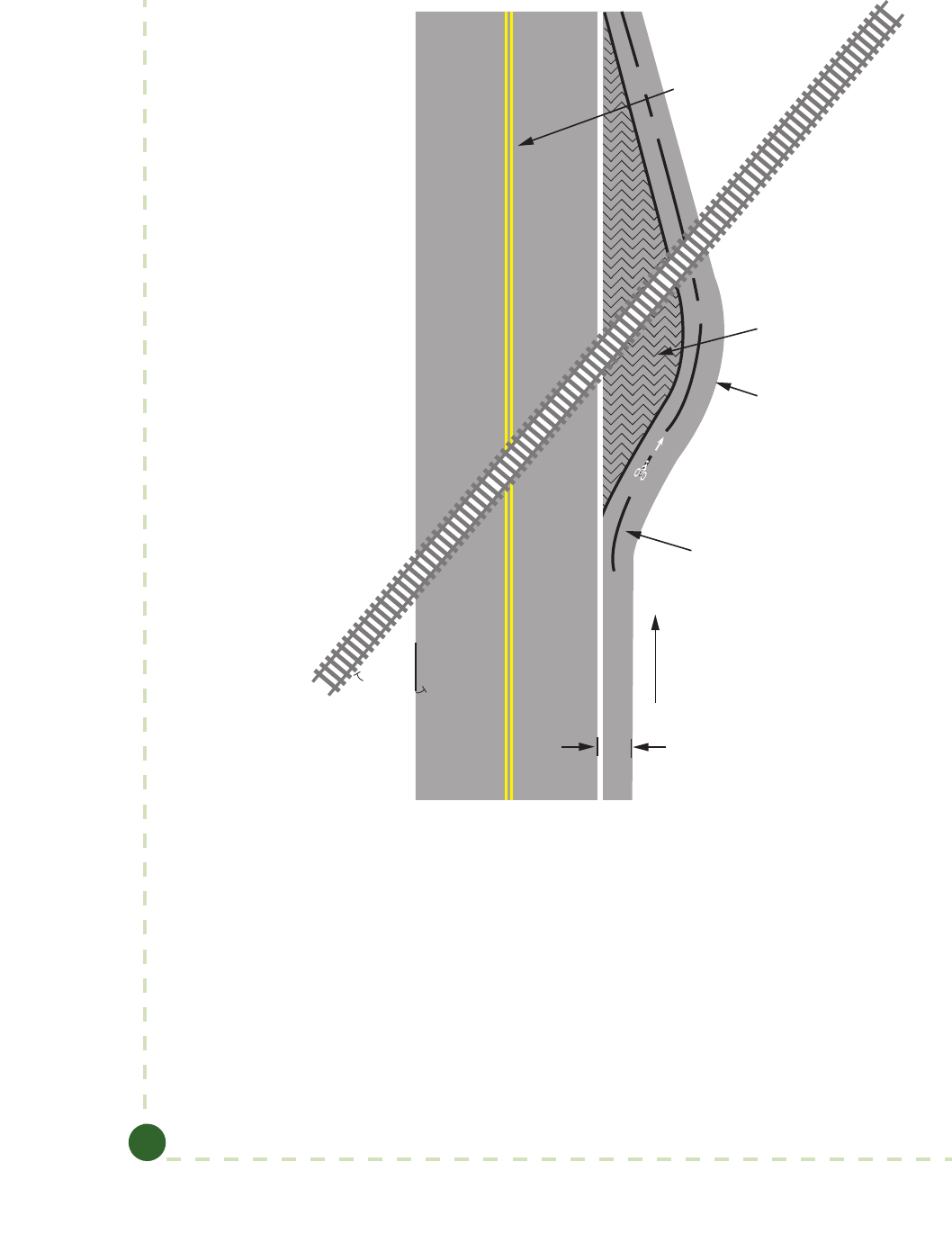
Guide to Bicycle Facilities, 4th Edition
4-40
Shoulder Bikeway
60˚–90˚
Direction of bike travel
Shoulder
Widen to permit right
angle crossing
Striped
Roadway
C
L
Figure 4-29. Correction for Skewed Railroad Grade Crossing—Widened Shoulder
4.12.2. Obstruction Markings
Barriers and obstructions, such as abutments, piers, rough grates, and other features constricting a
bikeway should be clearly marked to gain the attention of approaching bicyclists. is treatment
should be used only where the obstruction is unavoidable, and should not substitute for good
bikeway design; removing the obstruction is preferred. An example of an obstruction marking is
shown in Figure 4-30. Table 4-1 provides the equation for determining the taper length based on
MUTCD criteria (3). Table 3-2 presents typical bicycle approach speeds for use in this equation.
Signs, reectors, diagonal yellow markings, or other treatments from MUTCD Part 9 (3) may
also be appropriate to alert bicyclists to potential obstructions.
© 2012 by the American Association of State Highway and Transportation Officials.
All rights reserved. Duplication is a violation of applicable law.
Copyright American Association of State Highway and Transportation Officials
Provided by IHS under license with AASHTO
Licensee=Purdue University/5923082001
Not for Resale, 06/14/2012 21:55:46 MDT
No reproduction or networking permitted without license from IHS
--`,`,`,``,`,``,`````,```,`,```,-`-`,,`,,`,`,,`---

Chapter 4: Design of On-Road Facilities
4-41
For metric units:
L = 0.62WS, where S is bicycle approach speed in kilometers per hour
For English units:
L = WS, where S is bicycle approach speed in miles per hour
Direction of bicycle travel
Pier, abutment, grate, or other obstruction
Wide, solid white line
W
L
Figure 4-30. Obstruction Marking
Table 4-1. Formula for Determining Taper Length for Obstruction Markings
U.S. Customary Metric
L = WS L = 0.62WS
where: where:
L
=
taper length (ft) L
=
taper length (m)
W
=
offset width (ft) W
=
offset width (m)
S
=
bicycle approach speed (mph) S
=
bicycle approach speed (km/h)
Note: An additional 1 ft (0.3 m) of offset should be provided for a raised obstruction.
4.12.3 Bridges, Viaducts, and Tunnels
Bridges, viaducts, and tunnels should accommodate bicycles. As a general exception, these
structures do not need to accommodate bicycles on roadways where bicycle access is prohibited.
However, there are numerous examples of limited access highway bridges that cross major barriers
(such as wide waterways) that incorporate a shared use path for bicyclists and pedestrians.
e type of bicycle accommodation should be determined in consideration of the road function,
length of the bridge or tunnel (i.e., potential need for disabled vehicle storage), and the design of
the approach roadway. e absence of a bicycle accommodation on the approach roadway should
not prevent the accommodation of bicyclists on the bridge or tunnel. Shoulder improvements as-
sociated with bridge projects (approach shoulders) should include bicycle accommodations, such
as paved shoulders or bike lanes.
© 2012 by the American Association of State Highway and Transportation Officials.
All rights reserved. Duplication is a violation of applicable law.
Copyright American Association of State Highway and Transportation Officials
Provided by IHS under license with AASHTO
Licensee=Purdue University/5923082001
Not for Resale, 06/14/2012 21:55:46 MDT
No reproduction or networking permitted without license from IHS
--`,`,`,``,`,``,`````,```,`,```,-`-`,,`,,`,`,,`---

Guide to Bicycle Facilities, 4th Edition
4-42
e most common types of bicycle facilities that are provided on bridges and inside tunnels are
bike lanes in urban and suburban areas, and shoulders in rural locations. In most cases (except for
those cited below), the bicycle facility will be separated from the pedestrian facility (sidewalk).
In cases where a bridge on a controlled access freeway aects a non-controlled access roadway
(e.g., an overpass/underpass that serves as existing surface roadway), the project should include
appropriate access for bicycles on the non-limited access roadway, including such elements as bike
lanes, paved shoulders, and bicycle crossings at associated ramps.
In locations where bicyclists will operate in close proximity to bridge railings or barriers, the
railing or barrier should be a minimum of 42 in. (1.05 m) high. On bridges where bicycle speeds
are likely to be high (such as on a downgrade), and where a bicyclist could impact a barrier at a
25 degree angle or greater (such as on a curve), a higher 48-in. (1.2-m) railing may be considered.
Where a barrier is less than 42 in. (1.2 m) high, an aluminum rail with posts is usually mounted
on top of the barrier. If the shoulder is suciently wide so that a bicyclist does not operate in
close proximity to the rail, lower rail heights are acceptable.
Long Bridges
Long bridges often have higher motor vehicle speeds than their approach roadways. On bridges
with a continuous span over 0.5 mi (0.8 km) in length and design speeds that exceed 45 mph
(70 km/h), consideration should be given to providing a shared use path separated from trac
with a concrete barrier, preferably on both sides of the bridge. e provision of a pathway on one
side tends to result in wrong-way travel on the departures when bicyclists continue on the same
side of the road for some distance. If a pathway is only provided on one side, crossing provisions
(grade separated, where needed) should be provided on each end of the bridge to allow bicyclists
traveling against the ow of trac to cross over to the other side of the roadway and proceed
in a legal manner. See Section 5.2.10 for information on the appropriate widths of bridges and
underpasses.
Retrofits to Existing Bridges and Tunnels
At existing bridges and viaducts, there are often sudden changes in roadway geometry that can
signicantly reduce travel lane widths and negatively aect bicyclists’ comfort for the length of
the bridge span.
e preferred solution is to continue to enable bicyclist operation (riding with trac) on the
bridge or viaduct with shoulders or bike lanes by narrowing travel lanes where practical. Where
the deck of a bridge is too narrow to accommodate shoulder widths useful for bicyclists, it may
be feasible to widen a sidewalk to a shared use path width, e.g., by reducing travel lane widths or
installing a cantilever structure. In both cases, the weight increase must be compatible with the
structural suciency of the bridge. A ramp between the roadway and the sidewalk is needed at
either end of the bridge.
Retrot options for tunnels include widening an existing sidewalk, or eliminating a narrow side-
walk. e latter may not be practical where the sidewalk functions as a barrier curb to discourage
large vehicles from traveling too close to the side, or where it is intended for emergency access or
egress. In narrow tunnels where bicyclists share travel lanes with motor vehicles, one option is to
provide a warning sign and beacon at the tunnel entrance that can be activated by bicyclists. e
beacon should be designed to ash for the length of time that it will take for a typical bicyclist to
travel through the tunnel, to signal to a motorist that a bicyclist is present. Alternatively, a regula-
tory R4-11 sign (“BICYCLES MAY USE FULL LANE”) may be provided without a beacon.
© 2012 by the American Association of State Highway and Transportation Officials.
All rights reserved. Duplication is a violation of applicable law.
Copyright American Association of State Highway and Transportation Officials
Provided by IHS under license with AASHTO
Licensee=Purdue University/5923082001
Not for Resale, 06/14/2012 21:55:46 MDT
No reproduction or networking permitted without license from IHS
--`,`,`,``,`,``,`````,```,`,```,-`-`,,`,,`,`,,`---

Chapter 4: Design of On-Road Facilities
4-43
Adequate lighting is particularly important in these locations so that motorists can see and react
to bicyclists using the tunnel.
e installation of shared-lane markings informs bicyclists of where they should position them-
selves within the shared lane and may be serve to remind motorists of the possible presence of
bicycle on bridges or in tunnels.
4.12.4 Traffic Signals
Trac signals assign right of way to various trac movements at intersections. Traditionally,
signal design has been determined by the operating characteristics of motor vehicles. Bicyclists
typically use the same travelled way and signal displays as motorists. Bicyclists, however, have sig-
nicantly dierent operating characteristics; and it is, therefore, advisable to adjust signal opera-
tions for bicyclists. Although non‐motorized users of various types may cross at an intersection,
this section addresses only the needs of bicyclists.
Signal Considerations for Bicyclists
e dierences in operating characteristics of bicyclists have an impact on some signal design
elements. Important factors to consider are the speeds and behaviors of bicyclists. Experienced
bicyclists on higher classication roadways (major streets) are typically comfortable entering inter-
sections in the mid-to-late green due to longer greens available for major thoroughfares. However,
bicyclists on cross streets tend to slow down approaching the intersection even when approaching
on a green, in order to start at the beginning of green. Most bicyclists tend to stop at the onset of
yellow in the trac signal. Youth bicyclists often use crosswalks and pedestrian push buttons to
cross; therefore, these facilities should be accessible to bicyclists who may wish to proceed through
the intersection in this manner. ese behaviors and preferences have an impact on the selection
of signal timing parameters suitable for bicyclists. It is, therefore, important to evaluate bicyclist
needs at a trac signal by considering the scenarios of a stopped bicycle and a rolling bicycle.
e signal parameters that should be modied to accommodate bicyclists, when appropriate, are
the minimum green interval, all-red interval, and extension time:
 Minimum green is intended to eectively clear a vehicle through the intersection
from a stopped position. Bicycles need a longer minimum green than automobiles.
Some controllers have a bicycle minimum green parameter which can be used with
appropriate detection to service bicyclists.
 e all-red interval is used to provide time for crossing automobiles and bicyclists to
approach or pass beyond the far side of an intersection.
 Extension time or passage time is the time a detected automobile or bicyclist needs to
extend the green indication to provide enough time to clear the intersection before a
green indication is displayed to conicting trac.
e yellow interval is based on the approach speed of the automobiles and is usually between 3
and 6 seconds in duration. Generally, yellow change intervals calculated for automobiles using
commonly accepted formulas are adequate for bicycles.
In some instances, it may be appropriate to indicate that a signal head is intended for the exclu-
sive use of bicyclists. A sign can be added near the signal head that states “BICYCLE SIGNAL”.
© 2012 by the American Association of State Highway and Transportation Officials.
All rights reserved. Duplication is a violation of applicable law.
Copyright American Association of State Highway and Transportation Officials
Provided by IHS under license with AASHTO
Licensee=Purdue University/5923082001
Not for Resale, 06/14/2012 21:55:46 MDT
No reproduction or networking permitted without license from IHS
--`,`,`,``,`,``,`````,```,`,```,-`-`,,`,,`,`,,`---

Guide to Bicycle Facilities, 4th Edition
4-44
is may be appropriate where bicyclists share a signal phase with pedestrians or have their own
phase. It may also be appropriate at some path crossings of roadways.
Stopped Bicyclist
When an approach receives a green indication, a stopped bicyclist needs enough time to react,
accelerate, and cross the intersection before trac on the crossing roadway enters the intersection
on its green. is is referred to as standing bicycle crossing time, and is used to determine the
bicycle minimum green (BMG) time. Intersection crossing time for a bicyclist who starts from a
stop and attains crossing speed V within the intersection is shown in Table 4-2.
Table 4-2. Standing Bicycle Crossing Time
U.S. Customary Metric
where: where:
BCT
standing
=
bicycle crossing time (s) BCT
standing
=
bicycle crossing time (s)
W
=
intersection width (ft) W
=
intersection width (m)
L
=
typical bicycle length = 6 ft
(see Chapter 3 for other design
users)
L
=
typical bicycle length = 1.8 m
(see Chapter 3 for other design
users)
V
=
attained bicycle crossing speed
(ft/s)
V
=
attained bicycle crossing speed
(m/s)
PRT
=
perception reaction time = 1s PRT
=
perception reaction time = 1s
a
=
bicycle acceleration (1.5 ft/s
2
) a
=
bicycle acceleration (0.5 m/s
2
)
Most bicyclists can accelerate at a rate of at least 1.5 ft/s
2
(0.5 m/s
2
) and can obtain a speed of at
least 10 mph (14.7 ft/s) [16 km/h (4.5 m/s)]. Youth bicyclists often have slower reaction times
and need additional time to get started and accelerate. Extended crossing times should be consid-
ered where young riders are expected (e.g., near schools).
Bicyclists who begin crossing an intersection from a standing start on a new green take more time
to cross than rolling bicyclists who enter on green, since they have to accelerate. is time is usu-
ally more critical for bicyclists on minor road approaches, since minor-road crossing distance is
ordinarily greater than major-road crossing distance. Bicycle minimum green is determined using
the bicycle crossing time for standing bicycles and clearance time as shown in Table 4-3.
Some controllers have a built-in feature to specify and program a bicycle minimum green. If
appropriate bicycle detection exists, and a bicycle is detected stopped at the intersection, the
controller will provide the bicycle minimum green instead of the normal minimum green. If
this type of controller is not used, and if the minimum green needed for local bicyclists is greater
than what would otherwise be used, minimum green time should be increased. However, as
with all calculated signal timing, eld observations should be undertaken prior to making any
adjustments.
© 2012 by the American Association of State Highway and Transportation Officials.
All rights reserved. Duplication is a violation of applicable law.
Copyright American Association of State Highway and Transportation Officials
Provided by IHS under license with AASHTO
Licensee=Purdue University/5923082001
Not for Resale, 06/14/2012 21:55:46 MDT
No reproduction or networking permitted without license from IHS
--`,`,`,``,`,``,`````,```,`,```,-`-`,,`,,`,`,,`---

Chapter 4: Design of On-Road Facilities
4-45
Table 4-3. Bicycle Minimum Green Time Using Standing Bicycle Crossing Time
U.S. Customary Metric
where: where:
BMG
=
bicycle minimum green time (s) BMG
=
bicycle minimum green time (s)
BCT
standing
=
bicycle crossing time (s) BCT
standing
=
bicycle crossing time (s)
Y
=
yellow change interval (s) Y
=
yellow change interval (s)
R
clear
=
all-red (s) R
clear
=
all-red (s)
W
=
intersection width (ft) W
=
intersection width (m)
L
=
typical bicycle length = 6 ft
(see Chapter 3 for other design
users)
L
=
typical bicycle length = 1.8 m
(see Chapter 3 for other design
users)
V
=
bicycle speed crossing an inter-
section (ft/s)
V
=
bicycle speed crossing an inter-
section (m/s)
PRT
=
perception reaction time = 1s PRT
=
perception reaction time = 1s
a
=
bicycle acceleration (1.5 ft/s
2
) a
=
bicycle acceleration (0.5 m/s
2
)
Rolling Bicyclist
Rolling bicycle crossing time determines the adequacy of any red clearance interval and any
extension time, if provided. Although a small percentage of adult bicyclists travel at speeds below
10 mph (14.7 ft/s) [16 km/h (4.5 m/s)], most bicyclists momentarily can and do achieve higher
speeds. Under typical conditions, the speed (V) can be assumed to be at least this great. If the ap-
proach is on an appreciable upgrade or downgrade, a modied value may be appropriate.
When estimating whether adequate time is available for a rolling bicycle to cross the intersection
at the end of a green indication, the braking distance and the width of the intersection should
be considered. Towards the end of a green indication, beyond a certain point on the approach
to the intersection, the bicyclist can neither stop comfortably prior to the intersection nor clear
the intersection if clearance time is inadequate. A bicyclist needs some distance to brake and stop
comfortably. is distance depends on the bicyclist’s speed, perception reaction time, and decel-
eration rates. e equation for rolling bicycle crossing time considering braking distance is shown
in Table 4-4.
© 2012 by the American Association of State Highway and Transportation Officials.
All rights reserved. Duplication is a violation of applicable law.
Copyright American Association of State Highway and Transportation Officials
Provided by IHS under license with AASHTO
Licensee=Purdue University/5923082001
Not for Resale, 06/14/2012 21:55:46 MDT
No reproduction or networking permitted without license from IHS
--`,`,`,``,`,``,`````,```,`,```,-`-`,,`,,`,`,,`---

Guide to Bicycle Facilities, 4th Edition
4-46
Table 4-4. Rolling Bicycle Crossing Time Considering Braking Distance
U.S. Customary Metric
2
=
2
rolling
BD+W +L
BCT
V
V
BD=PRT ×V +
a
2
=
2
rolling
BD+W +L
BCT
V
V
BD=PRT ×V +
a
where: where:
BCT
rolling
=
bicycle crossing time (s)
BCT
rolling
=
bicycle crossing time (s)
W
=
intersection width (ft)
W
=
intersection width (m)
L
=
typical bicycle length = 6 ft
(see Chapter 3 for other design
users)
L
=
typical bicycle length = 1.8 (see
Chapter 3 for other design users)
V
=
bicycle speed crossing an
intersection (ft/s)
V
=
bicycle speed crossing an inter-
section (m/s)
BD
=
breaking distance (ft)
BD
=
breaking distance (m)
PRT
=
perception reaction time = 1s
PRT
=
perception reaction time = 1s
a
=
deceleration rate for wet
pavement = 5 ft/s
2
a
=
deceleration rate for wet
pavement = 1.5 m/s
2
A signal should provide sucient time for a rolling bicyclist who enters at the end of the green
interval to clear the intersection before trac on a crossing approach receives a green indication.
e time available for bicyclists to cross the intersection is composed of the yellow change inter-
val, all-red interval, and any extension time, if provided. (Extension time is time added to the
duration of a signal phase based on the volume of trac detected.) As previously stated, the yel-
low interval is based on the approach speeds of automobiles, and therefore should not be adjusted
in order to accommodate bicycles. However, it may be feasible to increase the all-red interval.
e time should be increased, where appropriate, up to the longest interval used in local practice.
Table 4-5 shows the equation used to determine the all-red interval and extension time needed
for the rolling bicycle crossing time.
If time for bicycle crossing is inadequate with maximum red clearance time, use of adaptive signal
timing for bicycles may be helpful. is technique extends green time when a bicycle approach-
ing late on green is detected. Trac engineers typically use extension time and call features within
trac signal controllers; however, the extension setting can also be applied within a specic
detector. An extension setting for a phase within a trac signal controller will extend the green
time for vehicles that actuate any detector that feeds the respective phase. However, an exten-
sion setting applied within a specic detector will extend the green time only for actuations on
that detector. erefore, when using an exclusive bicycle detector, it is recommended to use the
extend feature in the bicycle detector settings instead of the extension settings in the trac signal
controller.
Loop detectors cannot distinguish between bicycles and motor vehicles. erefore, in locations
utilizing loop detectors and extension time, a bike lane is typically needed on the approach in
order to provide a location where bicycles (and not automobiles) are detected. In the absence of
bike lanes, it may still be feasible to use video detection to distinguish approaching bicyclists. e
© 2012 by the American Association of State Highway and Transportation Officials.
All rights reserved. Duplication is a violation of applicable law.
Copyright American Association of State Highway and Transportation Officials
Provided by IHS under license with AASHTO
Licensee=Purdue University/5923082001
Not for Resale, 06/14/2012 21:55:46 MDT
No reproduction or networking permitted without license from IHS
--`,`,`,``,`,``,`````,```,`,```,-`-`,,`,,`,`,,`---

Chapter 4: Design of On-Road Facilities
4-47
braking distance mentioned earlier can also be used to help determine the location of the bicycle
detector so that adequate distance is provided for a bicyclist to stop prior to the intersection if
they do not reach the detector just before the end of the green interval. Detection for bicycles at
signals is discussed in the following section.
Table 4-5. All-Red and Extension Time Using Rolling Bicycle Crossing Time
U.S. Customary Metric
BCT
rolling
≤ T
extension
+ Y + R
clear
BCT
rolling
≤ T
extension
+ Y + R
clear
where: where:
BCT
rolling
=
bicycle crossing time (s)
BCT
rolling
=
bicycle crossing time (s)
T
extension
=
extension time (s)
T
extension
=
extension time (s)
Y
=
yellow change interval (s)
Y
=
yellow change interval (s)
R
clear
=
all-red (s)
R
clear
=
all-red (s)
4.12.5 Detection for Bicycles at Traffic Signals
Actuated trac signals should detect bicycles; otherwise, a bicyclist may be unable to call a green
signal and may be forced to break the law by violating a red signal. Various technologies are
available for detecting bicycles, including inductive loops, microwave, video, magnetometers, and
pushbuttons.
Inductive Loops
e metal rims of a bicycle intercept the horizontal magnetic eld above an inductive loop.
Diagonal quadrupole inductive loops, such as illustrated in Figure 4-31 have some horizontal
magnetic eld everywhere within the loop and thus are suitable for detecting bicycles. Other
types of inductive loops, such as the conventional quadrupole loop illustrated in Figure 4-32,
have a horizontal magnetic eld only above the loop slots and are thus generally unsuitable for
bicycle detection, particularly at new installations. For existing installations of conventional loops,
the MUTCD contains a bicycle detector symbol (see Figure 4-33) as a way of showing bicyclists
the location of the loop slot. is pavement marking can be supplemented by a R10-22 sign (see
Figure 4-34) to reinforce the message to the bicyclist.
A diagonal quadrupole loop can be used on shared use paths and bike lanes, as well as in travel
lanes on roadways. A diagonal quadrupole loop is particularly eective at rejecting vehicles in the
adjacent travel lane, allowing the use of a higher sensitivity setting on the detector amplier.
© 2012 by the American Association of State Highway and Transportation Officials.
All rights reserved. Duplication is a violation of applicable law.
Copyright American Association of State Highway and Transportation Officials
Provided by IHS under license with AASHTO
Licensee=Purdue University/5923082001
Not for Resale, 06/14/2012 21:55:46 MDT
No reproduction or networking permitted without license from IHS
--`,`,`,``,`,``,`````,```,`,```,-`-`,,`,,`,`,,`---

Guide to Bicycle Facilities, 4th Edition
4-48
15 in.
(380 mm)
30 in.
(760 mm)
27 in.
(685 mm)
Direction of Travel
Sawcut Detail
15 in.
(380 mm)
Winding DetailSymbol
30 in.
(760 mm)
27 in.
(685 mm)
Figure 4-31. Diagonal Quadrupole Loop Detector
Figure 4-32. Conventional Quadrupole Loop Detector
© 2012 by the American Association of State Highway and Transportation Officials.
All rights reserved. Duplication is a violation of applicable law.
Copyright American Association of State Highway and Transportation Officials
Provided by IHS under license with AASHTO
Licensee=Purdue University/5923082001
Not for Resale, 06/14/2012 21:55:46 MDT
No reproduction or networking permitted without license from IHS
--`,`,`,``,`,``,`````,```,`,```,-`-`,,`,,`,`,,`---

Chapter 4: Design of On-Road Facilities
4-49
2 in. (50 mm)
6 in. (150 mm)
6 in. (150 mm)
5 in. (125 mm)
24 in. (500 mm)
2 in. (50 mm)
10 in. (250 mm)
Figure 4-33. Typical Bicycle Detector Pavement Marking
Figure 4-34. Bicycle Detector Pavement Marking and Sign
© 2012 by the American Association of State Highway and Transportation Officials.
All rights reserved. Duplication is a violation of applicable law.
Copyright American Association of State Highway and Transportation Officials
Provided by IHS under license with AASHTO
Licensee=Purdue University/5923082001
Not for Resale, 06/14/2012 21:55:46 MDT
No reproduction or networking permitted without license from IHS
--`,`,`,``,`,``,`````,```,`,```,-`-`,,`,,`,`,,`---

Guide to Bicycle Facilities, 4th Edition
4-50
Video Detection Systems
Video detection uses a processor to analyze the video image from a video camera installed either
on a signal mast arm or on a pole at the intersection. is processor analyzes the image in zones
drawn by the operator on a monitor. When a vehicle enters the zone, the change in the image is
detected and a call is placed to the trac signal controller. Video detection can be used to detect
both moving and stationary objects. Even though some video detectors have problems detecting
vehicles, including bicycles, during poor lighting and weather conditions, many agencies continue
to use video detection for ease of installation and maintenance, and exibility in conguration.
Microwave (Radar) Detection Systems
Microwave detection uses a processor to analyze the reections from a radar transmitter/receiver
installed either on a signal mast arm or on a pole at the intersection. is processor analyzes the
reections in zones drawn by the operator on a monitor. When a vehicle or person enters the
zone, the change in the reection is detected and a call is placed to the trac signal controller.
Microwave detection can be used to detect both moving and stationary objects.
Magnetometer Detection Systems
Magnetometer detection uses a processor to analyze the changes produced in the Earth’s magnetic
eld by ferromagnetic material near a magnetometer installed in the pavement. Modern bicycles,
however, contain little ferromagnetic material and what ferromagnetic material they do contain is
located too far from the pavement to be detected by a magnetometer, so magnetometer detection
systems are unsuitable for bicycle detection.
Bicycle Pushbuttons
Bicycle pushbuttons require bicyclists to stop near them and thus are unsuitable as primary detec-
tors on roadways. Bicycle pushbuttons may be used on shared use paths and as a supplement on
roadways.
Location of Detection Zones
Bicycle detectors should be located in the expected path of bicyclists. On roadways, bicycle detec-
tors should at least extend across most of the width of the lane. On shared use paths, a bicycle
detector should either be located across the width of the lane or within easy reach of a stopped
bicyclist.
It may be desirable to install advance bicycle detection, similar to advance vehicle detection.
Where it is installed, advance detection makes it possible to minimize delay to bicyclists and
provide green extension time by installing one small area detection zone about 100 ft (30m)
from the stop bar, with a second, perhaps larger detection zone located at the stop bar (7). e
upstream detector should be located far enough from the intersection to allow for the bicycle
stopping distance. Another key consideration in the location of the upstream detector is to
avoid being triggered by right-turning vehicles. Both the advance and stop bar detectors must be
capable of detecting bicycles. When a bicycle is detected at the upstream loop, appropriate exten-
sion time is provided to hold the green to allow the bicycle to reach the loop at the stop bar.
Bicyclist Signal Timing
A bicyclist stopped at the stop bar when the signal turns green should be given enough time to
cross the intersection before the signal for the next conicting movement turns green. is can
be achieved either by providing minimum green, plus yellow, plus all-red at least sucient for
© 2012 by the American Association of State Highway and Transportation Officials.
All rights reserved. Duplication is a violation of applicable law.
Copyright American Association of State Highway and Transportation Officials
Provided by IHS under license with AASHTO
Licensee=Purdue University/5923082001
Not for Resale, 06/14/2012 21:55:46 MDT
No reproduction or networking permitted without license from IHS
--`,`,`,``,`,``,`````,```,`,```,-`-`,,`,,`,`,,`---

Chapter 4: Design of On-Road Facilities
4-51
a bicyclist initial start-up time of 6 seconds and a nal crossing speed of 10 mph (16 km/h) or
with a detection system that prevents the next conicting movement from turning green until the
bicyclist has cleared the intersection.
Maintenance of Traffic Detectors
Maintenance of trac detectors is discussed in Section 7.2.5.
4.12.6 Bicycles and Traffic Calming
Trac calming measures are intended to lessen undesirable trac impacts by restraining trac
speeds. Bicyclists operate at speeds close to what trac calming aims for; therefore, eective trac
calming will enhance bicycling on local streets. Bicyclists
could be considered the “design vehicle” for trac calm-
ing programs and projects; if they work well for bicyclists,
they should achieve other stated goals.
Reducing trac speeds can be accomplished through
physical constraints on the roadway, by reducing lateral
osets to roadside objects, or by creating a sense of en-
closure on the street corridor. Motorists typically drive at
speeds they perceive as safe; this is usually related to the
road design, especially available lane and roadway width
and the surrounding environment. e following sections
discuss individual trac calming techniques in light of
their potential advantages or disadvantages for bicycling.
Examples of trac calming treatments in current use are
presented in ITE’s Trac Calming State of the Practice: An
ITE Informational Report (6).
Narrow (Very Slow Speed) Streets
Narrow cross-sections can eectively reduce speeds, as
most motorists adjust their speed to the available lane
width. Narrow streets also reduce construction and
long-term maintenance costs. Eective widths for two-way local streets are 26–28 ft (7.9–8.5m)
with parking on both sides, and 20 ft (6.0m) with parking on one side. ese dimensions create
“queuing streets,” where oncoming motorists have to wait for the other to pull over into an avail-
able space at a driveway or empty parking spot. ese dimensions leave enough room for emer-
gency vehicle access, as well as the occasional moving van or large delivery truck.
 Eect on bicycling—positive, if operating speeds are reduced to 20–25 mph
(32–40 km/h). Bicyclists simply ride in the lane. is is a strategy that works best on
local and residential streets. On busier roads, narrow lanes are less comfortable for
bicyclists.
Vertical Deflections
Vertical deections include speed humps, speed tables, and speed cushions, as well as raised
intersections and raised crosswalks. Well-designed vertical deections allow vehicles to proceed
over the device at the intended speed with minimal discomfort, but will jolt the suspensions and
occupants of vehicles driven at higher speeds. Speed humps should be designed with a sinusoidal
Note: Not to scale.
Figure 4-35. Examples of Bicycle-Friendly Approach Profiles
for Speed Humps and Speed Tables
© 2012 by the American Association of State Highway and Transportation Officials.
All rights reserved. Duplication is a violation of applicable law.
Copyright American Association of State Highway and Transportation Officials
Provided by IHS under license with AASHTO
Licensee=Purdue University/5923082001
Not for Resale, 06/14/2012 21:55:46 MDT
No reproduction or networking permitted without license from IHS
--`,`,`,``,`,``,`````,```,`,```,-`-`,,`,,`,`,,`---

Guide to Bicycle Facilities, 4th Edition
4-52
prole, which is easier for bicyclists to traverse at normal bicycling speeds than a at, parabolic, or
circular prole (see Figure 4-35 for a comparison of sinusoidal and at proles). e front edge
or lip of the device should be as smooth as practical and meet the road with minimal vertical dis-
placement. Except in speed cushion applications, at-grade gaps should not be provided in vertical
deections for bicyclists to pass through, as motorists would take advantage of them, reducing the
eectiveness of the feature. To allow drainage in gutters, tapers may be needed to street grade on
the edges. Speed cushions, speed tables, raised intersections, and raised crosswalks usually use a
at ramp on each end, and a level area in the middle long enough to accommodate most wheel-
bases.
 Eect on bicycling—positive, as they reduce motor vehicle speeds, assuming that a
sinusoidal prole is used.
Speed bumps are vertical deections with heights comparable to speed humps but much shorter
traversal lengths (in the range of 1 to 3 ft [0.3 to 0.9 m], typically, in parking area applications).
eir use on public roads is unexpected and can result in a serious crash when bicyclists approach
them at speed, and fail to notice them in time.
Curb Extensions (Also Known as Chokers, Neckdowns, or Bulbouts)
Chokers constrict the street width to the traveled way minus the width of the nominal on-street
parking lane [usually 7 ft (2.1 m)]. ey are intended to reduce the pedestrian crossing distance,
slow right-turning vehicles, improve visibility between motorists and pedestrians, and provide
more space for landscaping and other features. Chokers should be highly visible and should not
extend beyond the width of the parking lane into the travel path of a bicyclist. e visibility of
curb extensions can be increased with bright paint on the curbs, and vertical elements such as
landscaping, benches, trashcans, re hydrants, and so forth. On busy thoroughfares, where lane
lines are striped, a line should be painted between the bike lane and the parking lane to guide
bicyclists past the curb extensions (see Figure 4-36).
 Eect on bicycling—positive, as long as the choker/curb extension is highly visible to
bicyclists.
Chicanes
By alternating placement of curb extensions (possibly including on‐street parking bays or low-
growing or narrow landscape features) from one side of the road to the other to establish a serpen-
tine alignment, a chicane reduces the speed of a driver following the curves.
 Eect on bicycling—generally neutral. Care should be taken that bicyclists are not
surprised by oncoming drivers, or squeezed by overtaking drivers, where the width of
the traveled way and sight lines have been reduced.
Traffic Circles
Trac circles are a neighborhood trac calming device for intersections. ey are typically 12 to
16 ft (3.7 to 4.9 m) in diameter, and often include low landscaping and mountable curbs so that
large vehicles can bypass the circle. ey are used to reduce speeds by deecting trac at inter-
sections (similar to a chicane) and reducing long vistas so that drivers tend to slow down. Trac
circles and roundabouts are addressed further in Section 4.12.11.
© 2012 by the American Association of State Highway and Transportation Officials.
All rights reserved. Duplication is a violation of applicable law.
Copyright American Association of State Highway and Transportation Officials
Provided by IHS under license with AASHTO
Licensee=Purdue University/5923082001
Not for Resale, 06/14/2012 21:55:46 MDT
No reproduction or networking permitted without license from IHS
--`,`,`,``,`,``,`````,```,`,```,-`-`,,`,,`,`,,`---

Chapter 4: Design of On-Road Facilities
4-53
 Eect on bicycling—positive. Trac circles allow bicyclists to maintain momentum
through intersections and are preferable to stop signs, which are often ignored by
bicyclists using neighborhood streets.
Figure 4-36. Curb Extensions
Creating a Sense of Enclosure
Establishing buildings at the back of the sidewalk, adding decorative pedestrian-scale lamp posts,
and planting tall trees at the street edge all help make the roadway appear narrower than it is.
Such treatments are most appropriate for very low speed streets.
 Eect on bicycling—positive, as trac speeds may be reduced with no constraints on
bicyclists.
4.12.7 Bicycles and Traffic Management
Trac management includes the use of traditional trac control devices to manage volumes
and routes of trac. Trac management is an area-wide treatment, rather than a solution for a
specic street. Trac management and trac calming are often complementary, and a plan to
retrot an area often includes a variety of tools from each.
© 2012 by the American Association of State Highway and Transportation Officials.
All rights reserved. Duplication is a violation of applicable law.
Copyright American Association of State Highway and Transportation Officials
Provided by IHS under license with AASHTO
Licensee=Purdue University/5923082001
Not for Resale, 06/14/2012 21:55:46 MDT
No reproduction or networking permitted without license from IHS
--`,`,`,``,`,``,`````,```,`,```,-`-`,,`,,`,`,,`---

Guide to Bicycle Facilities, 4th Edition
4-54
e following measures restrict trac access to local streets. is may result in some out-of-
direction travel for certain trips; however, if combined with a plan to develop a bicycle boulevard,
these strategies can improve bicycle access overall.
Multi-Way Stops
Stop signs are not a recommended trac management technique. All-way stops slow trac exces-
sively, encourage drivers to accelerate to higher speeds to make up for lost time, increase noise
and air pollution, and may increase crashes. All-way stop signs are often ignored where there is no
perceived need, breeding disrespect for their legitimate use.
 Eect on bicycling—negative, as bicyclists want to maintain their momentum; they
are often reluctant to come to a complete stop due to the added energy needed to
regain momentum.
One-Way Chokers
At certain intersections with thoroughfares, motor vehicles are restricted from entering a local
two-way street, but are allowed out; drivers must enter from another side street. Bicyclists can
be exempted from this restriction. is can be made possible with either a plaque (“EXCEPT
BICYCLES”) mounted under a “DO NOT ENTER SIGN” (see Figure 4-37), or by providing a
cut-through slot in a physical diverter. Two-way operation resumes immediately past the choker.
is is a common strategy used on bicycle boulevards (see Section 4.10), to reduce the amount of
motor vehicle trac along the route.
 Eect on bicycling—positive, as long as exemptions are allowed for bicyclists.
Diverters and Cul-de-Sacs
ese congurations separate otherwise adjoining street sections, preventing direct travel between
them. Caution should be used when physically restricting access, as this may contradict other
transportation goals, such as an open grid system. Cul-de-sacs may include pathways for bicycle
and pedestrian access that connect to adjacent streets and/or other cul-de-sacs to form a continu-
ous route.
 Eect on bicycling—positive if access to neighboring streets is provided. e eect
on bicycling is negative if through-access is not provided for bicyclists, as this limits
bicyclists’ ability to use low-volume local streets, and forces out-of-direction travel on
busier thoroughfares.
Note on one-way chokers and diverters: the benets to bicyclists are realized only if the cut-
throughs are well designed and well maintained. e design should allow bicyclists to proceed
with minimal change of direction or slowing; they should be in line with their path of travel (on
the right side of the roadway, with no sudden turns needed) and wide enough to allow passage
for a trailer or adult tricycle, or for two bicyclists, if two-way trac is accommodated in the cut-
through. A cut-through at a one-way choker only needs to accommodate one-way bicycle trac.
Maintenance is equally important; cut-throughs tend to accumulate debris, which should be
swept regularly to provide a clear path for bicyclists.
© 2012 by the American Association of State Highway and Transportation Officials.
All rights reserved. Duplication is a violation of applicable law.
Copyright American Association of State Highway and Transportation Officials
Provided by IHS under license with AASHTO
Licensee=Purdue University/5923082001
Not for Resale, 06/14/2012 21:55:46 MDT
No reproduction or networking permitted without license from IHS
--`,`,`,``,`,``,`````,```,`,```,-`-`,,`,,`,`,,`---

Chapter 4: Design of On-Road Facilities
4-55
DO NOT
ENTER
Figure 4-37. Choker with Bicycle Access
4.12.8 Drainage Grates and Utility Covers
Drainage grates with openings running parallel to the curb can cause narrow bicycle wheels to
drop into the gaps and cause a severe crash. Care should be taken that drainage grates are bicycle-
compatible, with openings small enough to prevent a bicycle wheel from falling into the slots
of the grate (Figure 4-38). e gap between the drainage grate and its frame should be 1 in.
(25mm) or less.
Another way to avoid drainage-grate concerns is to eliminate them entirely with the use of inlets
in the curb face. More inlets per mile may be needed to handle bypass ow. Another bicycle-
friendly option is to place the inlet grate entirely within the gutter of the street, rather than
extending it out into the traveled way.
Where bicycle-incompatible grates remain, metal straps can be welded across slots perpendicular
to the direction of travel at a maximum longitudinal spacing of 4 in. (100 mm), although care
should be taken that the grate does not become a debris collection site. ese should be checked
periodically to conrm that the straps remain in place. In general, this is only a temporary solu-
tion, and the location should ultimately be retrotted with bicycle-compatible drainage grates.
© 2012 by the American Association of State Highway and Transportation Officials.
All rights reserved. Duplication is a violation of applicable law.
Copyright American Association of State Highway and Transportation Officials
Provided by IHS under license with AASHTO
Licensee=Purdue University/5923082001
Not for Resale, 06/14/2012 21:55:46 MDT
No reproduction or networking permitted without license from IHS
--`,`,`,``,`,``,`````,```,`,```,-`-`,,`,,`,`,,`---

Guide to Bicycle Facilities, 4th Edition
4-56
Figure 4-38. Bicycle-Compatible Drainage Grates
Another concern arises when the roadway surface sinks, crumbles, or becomes otherwise unride-
able around a drainage grate. Surface grates should be ush with the road surface. Inlets should
be raised after a pavement overlay to within 0.25 in. (6 mm) of the new surface. If this is not
possible or practical, the pavement should taper into drainage inlets so it does not have an abrupt
edge at the inlet. Utility covers present similar concerns and should be installed ush with the
adjacent roadway surface.
4.12.9 Bicycle Travel on Freeways
Bicycling on freeways is prohibited in many states. In some states, however, bicycle operation is
permitted on freeway shoulders where authorized by maintaining agencies. is is typically done
where reasonable alternative routes are unavailable or deemed less suitable for bicycle travel than
the freeway. Where freeways are open to bicycle travel, bicyclist usage is usually infrequent. Crash
studies have found relatively few crashes involving bicyclists on freeways (6), (8). Where feasible
and practical, alternatives can be developed by improving existing routes or providing a shared
use path within or adjacent to the freeway right-of-way.
e following factors should be considered in determining the relative suitability of a freeway
segment and an alternative route:
 e wind blast eect of high-speed vehicle trac, particularly large trucks, should be
considered. Clear shoulder width (exclusive of rumble strips) should be sucient to
provide adequate separation between bicyclists and high-speed trac. Bicycle LOS
can be helpful in determining the appropriate shoulder width.
 e frequency and design of entrance/exit ramps should be considered. For example,
two-lane ramps are dicult for bicyclists to maneuver across. Flyover and left-side
ramps can create very dicult conditions for bicyclists, depending upon their con-
guration. Bicyclists should not have to merge across the through-lanes of a highway
to reach an exit.
 Heavy trac volumes on entrance/exit ramps can make it dicult for bicyclists to
cross ramps at certain times of the day.
At an exit beyond which bicyclists are not permitted to continue on a limited-access highway, a
sign should be posted to inform bicyclists of the requirement to exit.
© 2012 by the American Association of State Highway and Transportation Officials.
All rights reserved. Duplication is a violation of applicable law.
Copyright American Association of State Highway and Transportation Officials
Provided by IHS under license with AASHTO
Licensee=Purdue University/5923082001
Not for Resale, 06/14/2012 21:55:46 MDT
No reproduction or networking permitted without license from IHS
--`,`,`,``,`,``,`````,```,`,```,-`-`,,`,,`,`,,`---

Chapter 4: Design of On-Road Facilities
4-57
4.12.10 Bicycle Travel Through Interchange Areas
Like motorists, bicyclists often have to pass through freeway interchanges to access roads and
destinations on the other side of a freeway. In urban and suburban areas, bicyclists of all skill
levels travel on arterial and collector streets at freeway interchanges. ese interchanges can be sig-
nicant obstacles to bicycling if they are poorly designed. Travel on the crossroad through some
complex interchange designs may be particularly challenging for youth bicyclists.
In rural areas, trac volumes are usually low, and most recreational and touring bicyclists are
experienced enough to make their way through an interchange. Shoulder widths through inter-
changes should be wide enough for bicycle use.
Basic Design Principles at Freeway Interchanges
It is important to consider both convenience and the potential for crashes when accommodating
bicycle travel near interchanges. e issue of potential crashes becomes moot if facilities are not
used because of perceived inconvenience. e path bicyclists need to follow should be obvious
and logical, minimizing out-of-direction travel and grade changes. e interface between the
ramps and the local cross streets should minimize conicts so that both motorists and bicyclists
are aware of merging and crossing locations. Bike lanes or paved shoulders should be provided in
both directions.
e key areas for reducing bicycle crashes and increasing bicyclist convenience are at the freeway
ramp terminals, where freeway trac interacts with local trac and the speed dierential between
bicyclists and motor vehicles is often great. Designs that encourage high-speed and/or free-ow-
ing trac movements are the most dicult for bicyclists to negotiate. Designs that are functional
for bicycle passage typically encourage slowing or require motor-vehicle trac to slow or stop.
Bicyclists are best accommodated at interchanges by designing junctions as right-angle intersec-
tions (Figure 4-39) or roundabouts. Such designs restrain speeds, minimize conict areas, and
promote visibility. In this way, conicts between bicyclists and motorists are dealt with in a man-
ner familiar as most urban intersections:
 Motorists exiting the freeway and making a left turn onto the crossroad are controlled
by a stop sign or signal.
 Motorists exiting the freeway and making a right turn onto the crossroad are
controlled by a stop sign, signal, or yield sign, rather than allowing a free-owing
movement.
 Motorists turning left from the crossroad onto a freeway entrance ramp are con-
trolled by a trac signal or yield to oncoming trac, including bicyclists.
 A right-turn lane should be added with a taper for motorists turning right onto the
freeway entrance ramp. Where a bike lane is present on the approach, a bike lane
continuation should be provided along the left side of the right-turn lane. Since
motorists cross the path of bicyclists to enter the right-turn lane, they are required
to yield. is treatment can also be helpful where an approach has a paved shoulder,
providing for the correct positioning of the bicyclist at interchanges.
© 2012 by the American Association of State Highway and Transportation Officials.
All rights reserved. Duplication is a violation of applicable law.
Copyright American Association of State Highway and Transportation Officials
Provided by IHS under license with AASHTO
Licensee=Purdue University/5923082001
Not for Resale, 06/14/2012 21:55:46 MDT
No reproduction or networking permitted without license from IHS
--`,`,`,``,`,``,`````,```,`,```,-`-`,,`,,`,`,,`---

Guide to Bicycle Facilities, 4th Edition
4-58
Figure 4-39. Example of Bike Lane on the Crossroad at a Freeway Interchange
Single-Point Diamond Interchange (SPDI)
e single-point diamond interchange (Figure 4-40) is used in urban locations because of the
reduced need for right-of-way, its ability to handle high volumes of left-turning trac, and the
potential for improved cross street throughput. SPDIs can be made accessible to bicyclists by fol-
lowing these principles:
© 2012 by the American Association of State Highway and Transportation Officials.
All rights reserved. Duplication is a violation of applicable law.
Copyright American Association of State Highway and Transportation Officials
Provided by IHS under license with AASHTO
Licensee=Purdue University/5923082001
Not for Resale, 06/14/2012 21:55:46 MDT
No reproduction or networking permitted without license from IHS
--`,`,`,``,`,``,`````,```,`,```,-`-`,,`,,`,`,,`---

Chapter 4: Design of On-Road Facilities
4-59
 Each vehicular movement should be clearly dened and controlled.
 Exit and entry ramps should be designed at close-to-right angles.
 e right-turning movement o the local arterial onto the freeway should be accom-
modated by using a standard right-turn lane with a bike lane to the left, encouraging
motorists to yield to bicyclists when merging into the right-turn lane.
 Bicyclists should be able to proceed through the intersection in a straight line. Dotted
lane lines may be needed to guide bicyclists through wide intersections (see Figure
4-22).
 Careful consideration should be given to the trac signal timing. e fact that all
ramp terminals come to a single, signalized intersection creates a very large intersec-
tion, which can make it dicult to provide adequate signal clearance time for bicy-
clists. To address this concern, the signal phasing order should be as follows:
1. rough vehicles on the arterial.
2. Left-turn movements from the arterial to the freeway.
3. Left-turn movements from the freeway to the arterial.
Figure 4-40. Single-Point Diamond Interchange (SPDI)
© 2012 by the American Association of State Highway and Transportation Officials.
All rights reserved. Duplication is a violation of applicable law.
Copyright American Association of State Highway and Transportation Officials
Provided by IHS under license with AASHTO
Licensee=Purdue University/5923082001
Not for Resale, 06/14/2012 21:55:46 MDT
No reproduction or networking permitted without license from IHS
--`,`,`,``,`,``,`````,```,`,```,-`-`,,`,,`,`,,`---

Guide to Bicycle Facilities, 4th Edition
4-60
If the second phase is skipped (e.g., because no vehicle enters one of the left-turn lanes on the
crossroad), a through bicyclist might still be passing through the intersection when a green indi-
cation is displayed for the left-turn movements from the freeway exit ramps. To allow bicyclists
time to clear the conict area when this happens, use of a longer all-red interval may be needed
(see Section 4.12.4 on Trac Signals).
e SPDI can be designed to work reasonably well for bicyclists if it is the intersection of a local
thoroughfare and a freeway; bicyclists need to be accommodated only on the crossroad, but are
often not permitted on the freeway. If a SPDI is used for the grade-separated intersection of two
surface streets, both of which accommodate bicyclists, then the SPDI design is not eective, as
bicyclists on one of the streets will be in a freeway-like environment, with free-owing exiting and
merging ramps.
High-Speed Merge and Free-Flow Turn Lanes
As described above, congurations on arterials with high-speed merges and/or free-ow turn lanes
at interchanges are dicult for bicyclists to negotiate and should be discouraged. However, there
are many existing interchanges where high-speed merges and free-ow exit lanes are already in
use, and there are some situations where these high-speed movements are used to avoid unac-
ceptable levels of delay within the interchange. In addition, bike lanes are sometimes used on
urban parkways, which often have freeway-style merging lanes and turn ramps rather than simple
intersections. e diculties for bicyclists created by trac entering or exiting a roadway at high
speeds can be minimized using the designs below.
At some interchanges, it may be appropriate to allow bicyclists the option of using sidewalks,
particularly if this will provide access to a signalized crosswalk or other crossing situation that may
be more comfortable for some bicyclists. A disadvantage of this approach is that bicyclists riding
on sidewalks conict with pedestrians and may experience other operational diculties (see Sec-
tion 5.2.2). If this option is provided, there should be sidewalks on both sides, and they should be
wide enough for shared use by bicyclists and pedestrians.
Bicycle Lane Treatment at Merging Ramp Lanes
It is dicult for bicyclists to traverse the undened area created by right-lane merge movements,
because the acute angle of approach reduces visibility, and the speed dierential between bicyclists
and motorists is high because motor vehicles are accelerating to merge into trac. ere are two
approaches to the treatment of bike lanes at such locations:
1. e rst option is to simply allow bicyclists to choose their own merge, weave, or cross-
ing maneuvers, as depicted in Figure 4-41. Where the merge area is fairly short (i.e.,
bicyclists are exposed for less distance), it may be appropriate to continue bike lane or
shoulder markings as dotted lines through the merge area, if the ramp conguration is
such that merging trac is at fairly low speeds.
2. Where the merge distance is long and there are exceptionally high volumes of ramp traf-
c, it may be appropriate to provide a design that guides bicyclists in a manner that pro-
vides a short distance across the ramp at close to a right angle, and a crossing in an area
where sight lines are good and drivers’ attention is not entirely focused on merging with
trac (Figure 4-42). However, this conguration reverses the yielding relationships that
would otherwise apply (if a bicyclist continued on a direct path), and can involve delay
to bicyclists. Crosswalks should not be used at these locations, because vehicles merging
should not be expected to stop here.
© 2012 by the American Association of State Highway and Transportation Officials.
All rights reserved. Duplication is a violation of applicable law.
Copyright American Association of State Highway and Transportation Officials
Provided by IHS under license with AASHTO
Licensee=Purdue University/5923082001
Not for Resale, 06/14/2012 21:55:46 MDT
No reproduction or networking permitted without license from IHS
--`,`,`,``,`,``,`````,```,`,```,-`-`,,`,,`,`,,`---

Chapter 4: Design of On-Road Facilities
4-61
Figure 4-41. Option 1—Bike Lane and Free-Flow Merging Roadway
Figure 4-42. Option 2—Bike Lane and Free-Flow Merging Roadway
© 2012 by the American Association of State Highway and Transportation Officials.
All rights reserved. Duplication is a violation of applicable law.
Copyright American Association of State Highway and Transportation Officials
Provided by IHS under license with AASHTO
Licensee=Purdue University/5923082001
Not for Resale, 06/14/2012 21:55:46 MDT
No reproduction or networking permitted without license from IHS
--`,`,`,``,`,``,`````,```,`,```,-`-`,,`,,`,`,,`---

Guide to Bicycle Facilities, 4th Edition
4-62
Bicycle Lane Treatment at Diverging Ramp Lanes
Diverging ramp lanes present diculties for bicyclists because motorists expect to exit the road-
way with little reduction in speed, may fail to signal their maneuver, may pass bicyclists without
enough clearance, or may not yield to bicyclists before crossing their path of travel. In addition,
bicyclists may misjudge the intent of overtaking drivers who fail to use their turn signals. e best
way to accommodate bicyclists at an exit ramp is to develop a right-turn lane prior to the point
where the ramp diverges from the roadway, and place the bike lane to the left of the right-turn
lane, similar to a right-turn lane conguration at a right-angle intersection (see Figure 4-43).
Alternatively, where a ramp diverges from the roadway at a fairly steep angle, a bike lane can be
dotted across the diverge area and the “BEGIN RIGHT TURN LANE YIELD TO BIKES” sign
(R4‐4) placed at the beginning of the diverge area. In cases where motor vehicle speeds are high
and sidewalks are present, bicyclists may be given the option to exit onto the sidewalk and to pro-
ceed through the interchange along the pedestrian route. However the on-road bike lane should
still be provided for bicyclists who prefer to remain on the road. If a roadway lane is dropped
(i.e., leads directly to the diverging roadway), a design as shown in Figure 4-21 is appropriate. At
a diverging ramp that leads to a freeway, a jughandle design similar to that shown in Figure 4-29
may be provided so that bicyclists may cross the ramp at close to a right angle.
Figure 4-43. Example of Bike Lane and Diverging Roadway on an Arterial Street
Grade-Separated Crossings at Ramps
At especially complex interchanges where conicts between bicycles and high-speed and free-ow
motor vehicle movements are unavoidable, grade separation may be considered. Grade-separated
facilities add out-of-direction travel, and will not be used if the added distance is too great. is
can create an increased potential for crashes if bicyclists ignore the grade-separated facility and try
to negotiate the interchange at grade with no accommodations to facilitate this movement.
Ideally, grade separation is achieved by providing separated paths on both sides of the arterial
street that cross over or under the freeway ramps and the freeway itself, so approaching bicyclists
from either direction do not have to cross the arterial to continue through the interchange. If a
separated path for grade separation is provided on only one side of the interchange, some bicy-
clists will need to cross the arterial street in order to use the grade separation, and then they need
to cross back to continue on the correct side after going through the interchange.
Regardless of whether two paths or one path is used, clear directions should be given to guide
bicyclists’ movements at interchanges, particularly those that dier from standard bicycle opera-
tion. Structures, especially undercrossings, should be convenient and have good visibility so that
© 2012 by the American Association of State Highway and Transportation Officials.
All rights reserved. Duplication is a violation of applicable law.
Copyright American Association of State Highway and Transportation Officials
Provided by IHS under license with AASHTO
Licensee=Purdue University/5923082001
Not for Resale, 06/14/2012 21:55:46 MDT
No reproduction or networking permitted without license from IHS
--`,`,`,``,`,``,`````,```,`,```,-`-`,,`,,`,`,,`---

Chapter 4: Design of On-Road Facilities
4-63
they are properly used by bicyclists. Personal security is an important consideration as well, as
the grade separation may result in long sections of pathway that cannot be easily accessed in an
emergency. Adequate lighting is particularly important at these locations, but may not in itself
fully address personal security issues.
Shared use paths at interchanges should be designed to avoid signicant grade changes. Op-
portunities to provide direct links to destinations should be sought if they reduce travel distance
compared to the roadway alignment. Grade-separated crossings will also be used by pedestrians,
therefore they must meet accessibility standards; see Chapter 5 on “Shared Use Paths” for more
information.
4.12.11 Bicycle Travel at Roundabouts
Roundabouts are an increasingly popular design solution for intersections. Single-lane round-
abouts can provide signicant crash reduction benets for bicyclists when they are designed with
their needs in mind. At roundabouts, some bicyclists will choose to travel on the roadway, while
others will choose to travel on the sidewalk. Roundabouts can be designed to simplify this choice
for bicyclists.
General Roundabout Design Issues
Since typical on-road bicycle travel speeds are between 10 and 20 mph (15 and 30 km/h), round-
abouts that are designed to constrain motor vehicle speeds to similar values should reduce crashes
and improve usability for bicyclists. Urban roundabouts should have a maximum entry speed
of 20 to 30 mph (30 km/h to 50 km/h); single-lane roundabouts are typically at the lower end
of this range. e geometric features of a roundabout (e.g., entry and exit radius, entry and exit
width, splitter islands, circulatory roadway width, and inscribed circle diameter) should combine
to constrain motor-vehicle speeds (10).
Single-lane roundabouts are much simpler for bicyclists than multilane roundabouts, since bicy-
clists do not need to change lanes, and motorists are less likely to cut o bicyclists when they exit
the roundabout. erefore, when designing and implementing roundabouts, authorities should
avoid implementing multilane roundabouts before their capacity is needed. If “design year” trac
volumes indicate the need for a multilane roundabout, but this need is not likely for several years,
the roundabout can be built as a single-lane roundabout, and designed so that additional lanes
may be opened in the future when and if trac volumes increase. In addition, where a round-
about is proposed at an intersection of a major multilane street and a minor street, consideration
should be given to building a roundabout with two-lane approaches on the major street and one-
lane approaches on minor streets. When compared to roundabouts with two lanes at all four legs,
this design can signicantly reduce complexity for all users, including bicyclists.
Neighborhood trac circles are frequently used to provide trac calming on local streets in
urban and suburban neighborhoods. Neighborhood trac circles are similar in design to round-
abouts, but do not typically have an angled entry like that shown in Figure 4-44 to constrain
approach speeds of motor vehicles.
Designing for Bicycle Travel Within the Roundabout
In general, bicyclists who have the skills to ride in urban trac can manage single-lane round-
abouts with little diculty. Where appropriate design speeds are used, bicyclists can comfort-
ably merge into the lane of trac. Even at multilane roundabouts, many bicyclists will be able
to travel through roundabouts in the same manner as other vehicles, particularly during lower
volume periods.
© 2012 by the American Association of State Highway and Transportation Officials.
All rights reserved. Duplication is a violation of applicable law.
Copyright American Association of State Highway and Transportation Officials
Provided by IHS under license with AASHTO
Licensee=Purdue University/5923082001
Not for Resale, 06/14/2012 21:55:46 MDT
No reproduction or networking permitted without license from IHS
--`,`,`,``,`,``,`````,```,`,```,-`-`,,`,,`,`,,`---

Guide to Bicycle Facilities, 4th Edition
4-64
Bike lanes should be terminated in advance of roundabouts. e full-width bike lane should
normally end 100 ft (30 m) before the edge of the circulatory roadway (see Figure 4-44). Termi-
nating the bike lane cues bicyclists to merge into the lane of trac. An appropriate taper should
be provided to narrow the sum of the travel lane and bike lane widths down to an appropriate
entry width for the roundabout. e taper should end prior to the crosswalk at the roundabout,
to achieve the shortest practical pedestrian crossing distance. A taper rate of 7:1 is recommended
to accommodate a design speed of 20 mph (25 km/h). To taper a 5 to 6 ft- (1.5-to-1.8 m)-wide
bike lane, a 40 ft (12 m) taper is recommended. e bike lane line should be dotted for 50 to 200
ft (15 to 60 m) in advance of the taper. A longer dotted line encourages bicyclists to avail them-
selves of timely gaps to merge into trac, rather than delay until a point where, if no gap is avail-
able at the moment, the only practical alternative is to pause and wait for one. e bike lane line
should be terminated at the start of the taper or where the normal bike lane width is no longer
available. After the bike lane is terminated, shared-lane markings may be used.
50–200 ft (15–60 m)
min.
100 ft (30 m)
min.
50 ft (15 m)
min.
Landscaping strip
Ramp up
for bicycle
(See Detail “A”)
7:1 taper rate
min.
50 ft (15 m)
min.
Ramp down for bicycle
Dectable warning surface
Detail “A”
20° to 45° Typical
35° to 45°
Typical
6 ft (1.8 m)
Typical
Figure 4-44. Typical Layout of Roundabout with Bike Lanes (
4
)
© 2012 by the American Association of State Highway and Transportation Officials.
All rights reserved. Duplication is a violation of applicable law.
Copyright American Association of State Highway and Transportation Officials
Provided by IHS under license with AASHTO
Licensee=Purdue University/5923082001
Not for Resale, 06/14/2012 21:55:46 MDT
No reproduction or networking permitted without license from IHS
--`,`,`,``,`,``,`````,```,`,```,-`-`,,`,,`,`,,`---

Chapter 4: Design of On-Road Facilities
4-65
Bike lanes should not be located within the circulatory roadway of roundabouts. is design
would suggest that bicyclists should ride at the outer edge of the circulatory roadway, which
creates turning conicts at exits and entrances. At roundabout exits, an appropriate taper should
begin after the crosswalk, with a dotted line for the bike lane through the taper. e solid bike
lane line should resume as soon as the normal bike lane width is available.
Designing for Bicyclists to Traverse Roundabouts on the Sidewalk
Some on-road bicyclists, including children, may not feel comfortable navigating roundabouts on
the roadway. Bicycle ramps can be provided to allow access to the sidewalk or a shared use path
at the roundabout. Bicycle ramps at roundabouts have the potential to be confused as pedestrian
ramps, particularly for pedestrians who have visual impairments. erefore, bicycle ramps should
only be used where the roundabout complexity or design speed may result in less comfort for
some bicyclists. As described above, multilane roundabouts are more challenging for bicyclists;
therefore bicycle ramps can be useful in these locations. Bicycle ramps may also be appropriate at
single-lane roundabouts, if trac speeds or other conditions (e.g., a right-turn bypass lane) make
circulating like other vehicles more challenging for bicyclists. Otherwise, ramps are not normally
needed at urban, single-lane roundabouts.
Where bicycle ramps are provided at a roundabout, the publication Roundabouts: An Informa-
tional Guide (10) anticipates that some bicyclists may choose to leave the roadway and travel as
pedestrians to the other side of the roundabout. Consideration may also be given to providing
sidewalks with the width recommended for shared use paths (see Section 5.2.1) near round-
abouts. In areas with relatively low pedestrian usage and where bicycle usage of the sidewalks is
expected to be low, the normal sidewalk width may be sucient. In some jurisdictions, state or
local laws may prohibit bicyclists from riding on sidewalks. In these areas, bicycle ramps would
allow less condent bicyclists to walk their bicycles, as a pedestrian, to their desired exit from the
roundabout.
e design details of bicycle ramps are critical to their usability, to provide choice to bicyclists,
and to reduce the potential for confusion of pedestrians, particularly those who are blind or who
have low vision. Bicycle ramps should be placed at the end of the full width bike lane, just before
the beginning of the taper for the bike lane. Bicyclists approaching the taper and bike ramp will
thus be provided the choice of merging left into the travel lane, or moving to the right onto the
sidewalk. Where no bike lane is present on the approach to a roundabout, a bicycle ramp, if used,
should be placed at least 50 ft (15 m) prior to the crosswalk at the roundabout. Bicycle ramps
should be placed at a 35 to 45 degree angle to the roadway to enable bicyclists to use the ramp
even if pulling a trailer, but to discourage them from entering the sidewalk at high speed. Ideally,
the sidewalk approaching the roundabout is separated from the roadway with a buer strip, al-
lowing the ramp to be placed outside of the normal sidewalk area. In this case, the bike ramp can
be fairly steep, as it is not intended for pedestrian use (up to 20 percent slope). If placed within
the sidewalk area itself, the ramp slope must be built in a manner so that pedestrians are unlikely
to trip. A bicycle ramp should not be placed directly in line with the bike lane or otherwise placed
in a manner that appears to encourage or require its use.
Since bike ramps can be confusing for pedestrians with visual impairments, detectable warnings
should be included on the ramp. Where the ramp is placed in a buer strip, the detectable warn-
ings should be placed at the top of the ramp, as the ramp itself is part of the vehicular travel facil-
ity. If the ramp is in the sidewalk itself, the detectable warning should be placed at the bottom of
the ramp. Other aspects of the bike ramp design and placement can help keep pedestrians from
misconstruing the bike ramp as a pedestrian crossing location. ese aspects include the angle of
© 2012 by the American Association of State Highway and Transportation Officials.
All rights reserved. Duplication is a violation of applicable law.
Copyright American Association of State Highway and Transportation Officials
Provided by IHS under license with AASHTO
Licensee=Purdue University/5923082001
Not for Resale, 06/14/2012 21:55:46 MDT
No reproduction or networking permitted without license from IHS
--`,`,`,``,`,``,`````,```,`,```,-`-`,,`,,`,`,,`---

Guide to Bicycle Facilities, 4th Edition
4-66
the ramp, the possible steeper slope of the ramp, and location of the ramp relatively far from the
roundabout and marked crosswalk location.
Bicycle ramps at roundabout exits should be built with similar geometry and placement as the
ramps at roundabout entries. Bike ramps should be placed at least 50 ft (15 m) beyond the cross-
walk at the roundabout exit.
RefeRences
1. AASHTO. A Policy on Geometric Design of Highways and Streets. American Association of
State Highway and Transportation Ocials, Washington, DC, 2011.
2. AASHTO. U.S. Bicycle Route System. American Association of State Highway and Trans-
portation Ocials. http://www.transportation.org/Default.aspx?SiteID=68
3. FHWA. Manual on Uniform Trac Control Devices for Streets and Highways. Federal Highway
Administration, U.S. Department of Transportation, Washington, DC, 2009.
4. FHWA. Technical Summary: Roundabouts. FHWA-SA-10-006. Federal Highway Administra-
tion, U.S. Department of Transportation, Washington, DC, 2010.
5. ITE. Trac Calming State of the Practice: An ITE Informational Report. Institute of Transpor-
tation Engineers, Washington, DC, 1999.
6. Iowa Department of Transportation. Guidelines for the Conversion of Urban Four-
Lane Undivided Roadways to ree-Lane Two-Way Left-Turn Lane Facilities. Center for
Transportation Research and Education, Iowa State University, Ames, IA, 2001.
7. Kein, L. L, M. K. Mills, and D.R.P. Gibson. Trac Detector Handbook. Federal Highway
Administration, U.S. Department of Transportation, Washington, DC, 2006.
8. Moeur, R. C. and M. N. Bina. Bicycle–Motor Vehicle Collisions on Controlled Access Highways
in Arizona. s.l. Arizona Department of Transportation, Phoenix, AZ, 2002.
9. Potts, I.B, D. W. Harwood, and K. R. Richard. Relationship of Lane Width to Safety for
Urban and Suburban Arterials. In Transportation Research Record 2023. Transportation
Research Board, National Research Council, Washington, DC, 2007.
10. Rodegerdts, L., et al. National Cooperative Highway Research Report 672: Roundabouts: An In-
formational Guide, Second Edition. Transportation Research Board, Washington, DC, 2010.
11. Torbic, D. J., et al. National Cooperative Highway Research Report 641: Guidance for the De-
sign and Application of Shoulder and Centerline Rumble Strips. Transportation Research Board,
Washington, DC, 2009.
© 2012 by the American Association of State Highway and Transportation Officials.
All rights reserved. Duplication is a violation of applicable law.
Copyright American Association of State Highway and Transportation Officials
Provided by IHS under license with AASHTO
Licensee=Purdue University/5923082001
Not for Resale, 06/14/2012 21:55:46 MDT
No reproduction or networking permitted without license from IHS
--`,`,`,``,`,``,`````,```,`,```,-`-`,,`,,`,`,,`---

5-1
5
Photo courtesy of Maryland State
Highway Administration.
5.1 INTRODUCTION
Shared use paths are bikeways that are physically separated from
motorized vehicular trac by an open space or barrier and ei-
ther within the highway right-of-way or within an independent
right-of-way. Shared use paths are sometimes referred to as “trails.”
However, in many states the term “trail” means an unimproved
recreational facility. Care should be taken not to use these terms
interchangeably because they have distinctly dierent design guide-
lines. Shared use paths should be designed based on the guidance
in this guide.
Path users are generally non-motorized and may include but are
not limited to:
 Typical upright adult bicyclists
 Recumbent bicyclists
 Bicyclists pulling trailers
 Tandem bicyclists
 Child bicyclists
 Inline skaters
 Roller skaters
 Skateboarders
 Kick scooter users
 Pedestrians (including walkers, runners, people using
wheelchairs (both non-motorized and motorized),
people with baby strollers, people walking dogs, and
others.
Design of
Shared Use Paths
© 2012 by the American Association of State Highway and Transportation Officials.
All rights reserved. Duplication is a violation of applicable law.
Copyright American Association of State Highway and Transportation Officials
Provided by IHS under license with AASHTO
Licensee=Purdue University/5923082001
Not for Resale, 06/14/2012 21:55:46 MDT
No reproduction or networking permitted without license from IHS
--`,`,`,``,`,``,`````,```,`,```,-`-`,,`,,`,`,,`---

Guide to Bicycle Facilities, 4th Edition
5-2
Paths are most commonly designed for two-way travel, and the guidance herein assumes a two-
way facility is planned unless otherwise stated.
Shared use paths can serve a variety of purposes. ey can provide users with a shortcut through a
residential neighborhood (e.g., a connection between two cul-de-sac streets) or access to schools.
ey can provide a commuting route between residential areas and job centers or schools. Lo-
cated in a park or a greenway, they can provide an enjoyable recreational opportunity. Shared use
paths can be located along rivers, ocean fronts, canals, abandoned or active railroad and utility
rights-of-way, roadway corridors, limited access freeways, within college campuses, or within
parks and open space areas. Shared use paths can also provide bicycle access to areas that are oth-
erwise served only by limited-access highways. Shared use paths that run adjacent to a roadway
are called sidepaths. ese are discussed further in Section 5.2.2.
Shared use paths should be thought of as a system of o-road transportation routes for bicyclists
and other users that extends and complements the roadway network. Shared use paths should not
be used to preclude on-road bicycle facilities, but rather to supplement a network of on-road bike
lanes, shared roadways, bicycle boulevards, and paved shoulders. Shared use path design is similar
to roadway design, but on a smaller scale and with typically lower design speeds.
5.1.1 Accessibility Requirements for Shared Use Paths
Due to the fact that nearly all shared use paths are used by pedestrians, they fall under the ac-
cessibility requirements of the Americans with Disabilities Act (ADA). e technical provisions
herein either meet or exceed those recommended in current accessibility guidelines. Paths in a
public right-of-way that function as sidewalks should be designed in accordance with the pro-
posed Public Rights-of-Way Accessibility Guidelines (PROWAG) (13), or subsequent guidance that
may supersede PROWAG in the future. ese guidelines also apply to street crossings for all types
of shared use paths.
Shared use paths built in independent rights-of-way should meet the draft accessibility guidelines
in the Advance Notice of Proposed Rulemaking (ANPRM) on Accessibility Guideline for Shared Use
Paths (12), or any subsequent rulemaking that supersedes the ANPRM. e ANPRM separates
shared use paths from recreational trails and more closely aligns draft accessibility provisions
with those provided for sidewalks and other pedestrian facilities. Refer to the U.S. Access Board
website (www.access-board.gov) for up-to-date information regarding the accessibility provisions
for shared use paths and other pedestrian facilities covered by the Americans with Disabilities Act
and the Architectural Barriers Act.
5.2 ELEMENTS OF DESIGN
Shared use path design criteria are based on the physical and operating characteristics of path
users, which are substantially dierent than motor vehicles. Due to a large percentage of path
users being adult bicyclists, they are the primary design user for shared use paths and are the basis
for most of the design recommendations in this chapter. is chapter also provides information
on critical design issues and values for other potential design users, which should be used in the
event that large volumes of these other user types are anticipated.
Some paths are frequently used by children. e operating characteristics of child bicyclists are
highly variable, and their specic characteristics have not yet been fully dened through research
© 2012 by the American Association of State Highway and Transportation Officials.
All rights reserved. Duplication is a violation of applicable law.
Copyright American Association of State Highway and Transportation Officials
Provided by IHS under license with AASHTO
Licensee=Purdue University/5923082001
Not for Resale, 06/14/2012 21:55:46 MDT
No reproduction or networking permitted without license from IHS
--`,`,`,``,`,``,`````,```,`,```,-`-`,,`,,`,`,,`---

Chapter 5: Design of Shared Use Paths
5-3
studies. However, it is generally assumed that the speed of youth bicyclists is lower than adult
bicyclists. Since much of the design criteria in this guide is based on design speed, children will be
accommodated to a large extent. When considering criteria unrelated to design speed, engineer-
ing judgment should be used when modifying these values for children. roughout this chapter,
several design measures are recommended which are based primarily on pedestrian research. It
is presumed that these measures will also benet bicyclists and other path users, although the
research has not been conducted to support this assumption.
5.2.1 Width and Clearance
e usable width and the horizontal clearance for a shared use path are primary design consid-
erations. Figure 5-1 depicts the typical cross section of a shared use path. e appropriate paved
width for a shared use path is dependent on the context, volume, and mix of users. e minimum
paved width for a two-directional shared use path is 10 ft (3.0 m). Typically, widths range from
10 to 14 ft (3.0 to 4.3 m), with the wider values applicable to areas with high use and/or a wider
variety of user groups.
In very rare circumstances, a reduced width of 8 ft (2.4 m) may be used where the following
conditions prevail:
 Bicycle trac is expected to be low, even on peak days or during peak hours.
 Pedestrian use of the facility is not expected to be more than occasional.
 Horizontal and vertical alignments provide frequent, well-designed passing and rest-
ing opportunities.
 e path will not be regularly subjected to maintenance vehicle loading conditions
that would cause pavement edge damage.
In addition, a path width of 8 ft (2.4 m) may be used for a short distance due to a physical
constraint such as an environmental feature, bridge abutment, utility structure, fence, and such.
Warning signs that indicate the pathway narrows (W5-4a), per the MUTCD (7) should be con-
sidered at these locations.
A wider path is needed to provide an acceptable level of service on pathways that are frequently
used by both pedestrians and wheeled users. e Shared Use Path Level of Service Calculator is
helpful in determining the appropriate width of a pathway given existing or anticipated user
volumes and mixes (9). Wider pathways, 11 to 14 ft (3.4 to 4.2 m) are recommended in locations
that are anticipated to serve a high percentage of pedestrians (30 percent or more of the total
pathway volume) and high user volumes (more than 300 total users in the peak hour). Eleven
foot (3.4 m) wide pathways are needed to enable a bicyclist to pass another path user going the
same direction, at the same time a path user is approaching from the opposite direction (see Fig-
ure 5-2) (8). Wider paths are also advisable in the following situations:
 Where there is signicant use by inline skaters, adult tricycles, children, or other users
that need more operating width (see Chapter 3);
 Where the path is used by larger maintenance vehicles;
© 2012 by the American Association of State Highway and Transportation Officials.
All rights reserved. Duplication is a violation of applicable law.
Copyright American Association of State Highway and Transportation Officials
Provided by IHS under license with AASHTO
Licensee=Purdue University/5923082001
Not for Resale, 06/14/2012 21:55:46 MDT
No reproduction or networking permitted without license from IHS
--`,`,`,``,`,``,`````,```,`,```,-`-`,,`,,`,`,,`---

Guide to Bicycle Facilities, 4th Edition
5-4
 On steep grades to provide additional passing area; or
 rough curves to provide more operating space.
Not less than 2 ft
(0.6 m)
Not less than
4 ft (1.2 m)
Edge of shared-use path
2 ft
A
(0.6 m)
2 ft
A
(0.6 m)
10–14
B
(3.0–4.2 m)
Post-mounted
sign or other
traffic control
device
Notes:
A
(1V:6H) Maximum slope (typ.)
B
More if necessary to meet anticipated volumes and mix of users, per the
Shared Use Path Level of Service Calculator
(
9
)
Figure 5-1. Typical Cross Section of Two-Way, Shared Use Path on Independent Right-of-Way
Passing maneuver
11 ft (3.4 m)
Figure 5-2. Minimum Width Needed to Facilitate Passing on a Shared Use Path
Under most conditions, there is no need to segregate pedestrians and bicyclists on a shared use
path, even in areas with high user volumes—they can typically coexist. Path users customarily
keep right except to pass. Signs may be used to remind bicyclists to pass on the left and to give an
© 2012 by the American Association of State Highway and Transportation Officials.
All rights reserved. Duplication is a violation of applicable law.
Copyright American Association of State Highway and Transportation Officials
Provided by IHS under license with AASHTO
Licensee=Purdue University/5923082001
Not for Resale, 06/14/2012 21:55:46 MDT
No reproduction or networking permitted without license from IHS
--`,`,`,``,`,``,`````,```,`,```,-`-`,,`,,`,`,,`---

Chapter 5: Design of Shared Use Paths
5-5
audible warning prior to passing other slower users. Part 9 of the MUTCD (7) provides a variety
of regulatory signs that can be used for this purpose.
On pathways with heavy peak hour and/or seasonal volumes, or other operational challenges such
as sight distance constraints, the use of a centerline stripe on the path can help clarify the direc-
tion of travel and organize pathway trac. A solid yellow centerline stripe may be used to sepa-
rate two directions of travel where passing is not permitted, and a broken yellow line may be used
where passing is permitted. e centerline can either be continuous along the entire length of the
path, or may be used only in locations where operational challenges exist. Per the MUTCD, all
markings used on bikeways shall be retroreective.
In areas with extremely heavy pathway volumes, segregation of pedestrians from wheeled users
may be appropriate; however, care should be taken that the method of segregation is simple and
straightforward. Pedestrians are typically provided with a bi-directional walking lane on one side
of the pathway, while bicyclists are provided with directional lanes of travel. is solution should
only be used when a minimum path width of 15 ft (4.6 m) is provided, with at least 10 ft (3 m)
for two-way wheeled trac, and at least 5 ft (1.5 m) for pedestrians.
Where this type of segregation is used on a path with a view (e.g., adjacent to a lake or river), the
pedestrian lane should be placed on the side of the path with the view. Again, this solution should
only be used for pathways with heavy volumes, as pedestrians will often walk in the “bicycle only”
portion of a pathway unless it is heavily traveled by bicycles.
Another solution is to provide physically separated pathways for pedestrians and wheeled users.
A number of factors should be considered when determining whether to provide separate paths,
such as general site conditions (i.e., the width of separation and setting), origins and destina-
tions of dierent types of path users, and the anticipated level of compliance of users choosing
the appropriate path. In some instances, the dual paths may have to come in close proximity or
be joined for a distance due to site constraints. As allowed by the MUTCD (7) and described in
more detail in Section 5.4.2, mode-specic signs may be used to guide users to their appropriate
paths.
Ideally, a graded shoulder area at least 3 to 5 ft (0.9 to 1.5 m) wide with a maximum cross-slope
of 1V:6H, which should be recoverable in all weather conditions, should be maintained on each
side of the pathway. At a minimum, a 2 ft (0.6 m) graded area with a maximum 1V:6H slope
should be provided for clearance from lateral obstructions such as bushes, large rocks, bridge
piers, abutments, and poles. e MUTCD requires a minimum 2 ft (0.6 m) clearance to post-
mounted signs or other trac control devices (7). Where “smooth” features such as bicycle
railings or fences are introduced with appropriate aring end treatments (as described below), a
lesser clearance (not less than 1 ft [0.3 m]) is acceptable. If adequate clearance cannot be provided
between the path and lateral obstructions, then warning signs, object markers, or enhanced con-
spicuity and reectorization of the obstruction should be used.
Where a path is adjacent to parallel bodies of water or downward slopes of 1V:3H or steeper,
a wider separation should be considered. A 5 ft (1.5 m) separation from the edge of the path
pavement to the top of the slope is desirable. Depending on the height of the embankment and
condition at the bottom, a physical barrier, such as dense shrubbery, railing, or fencing may be
needed. is is an area where engineering judgment should be applied, as the risk for a bicyclist
who runs o the path should be compared to the risk posed by the rail. Where a recovery area
© 2012 by the American Association of State Highway and Transportation Officials.
All rights reserved. Duplication is a violation of applicable law.
Copyright American Association of State Highway and Transportation Officials
Provided by IHS under license with AASHTO
Licensee=Purdue University/5923082001
Not for Resale, 06/14/2012 21:55:46 MDT
No reproduction or networking permitted without license from IHS
--`,`,`,``,`,``,`````,```,`,```,-`-`,,`,,`,`,,`---

Guide to Bicycle Facilities, 4th Edition
5-6
(i.e., distance between the edge of the path pavement and the top of the slope) is less than 5ft
(1.5 m), physical barriers or rails are recommended in the following situations (see Figure 5-3):
 Slopes 1V:3H or steeper, with a drop of 6 ft (1.8 m) or greater;
 Slopes 1V:3H or steeper, adjacent to a parallel body of water or other substantial
obstacle;
 Slopes 1V:2H or steeper, with a drop of 4 ft (1.2 m) or greater; and
 Slopes 1V:1H or steeper, with a drop of 1 ft (0.3 m) or greater.
e barrier or rail should begin prior to, and extend beyond the area of need. e lateral oset
of the barrier should be at least 1 ft (0.3 m) from the edge of the path. e ends of the barrier
should be ared away from the path edge. Barrier or rail ends that remain within the 2 ft (0.6m)
clear area should be marked with object markers.
Railings that are used to protect users from slopes or to discourage path users from venturing
onto a roadway or neighboring property can typically have relatively large openings. A typical
design includes two to four horizontal elements with vertical elements spaced fairly widely, but
frequently enough to provide the needed structural support and in accordance with applicable
building codes. Where there is a high vertical drop or a body of water adjacent to the path where
a railing is provided, engineering judgment should be used to determine whether a railing suitable
for bridges (as described in Section 5.2.10) should be provided.
Other materials in addition to railings can be used to separate paths from adjacent areas, either
due to substantial obstacles or to discourage pathway users from venturing onto adjacent proper-
ties. Berms and/or vegetation can serve this function.
It is not desirable to place the pathway in a narrow corridor between two fences for long distanc-
es, as this creates personal security issues, prevents users who need help from being seen, prevents
path users from leaving the path in an emergency, and impedes emergency response.
e desirable vertical clearance to obstructions is 10 ft (3.0 m). Fixed objects should not be
permitted to protrude within the vertical or horizontal clearance of a shared use path. e recom-
mended minimum vertical clearance that can be used in constrained areas is 8 ft (2.4m). In
some situations, vertical clearance greater than 10 ft (3.0 m) may be needed to permit passage of
maintenance and emergency vehicles.
© 2012 by the American Association of State Highway and Transportation Officials.
All rights reserved. Duplication is a violation of applicable law.
Copyright American Association of State Highway and Transportation Officials
Provided by IHS under license with AASHTO
Licensee=Purdue University/5923082001
Not for Resale, 06/14/2012 21:55:46 MDT
No reproduction or networking permitted without license from IHS
--`,`,`,``,`,``,`````,```,`,```,-`-`,,`,,`,`,,`---

Chapter 5: Design of Shared Use Paths
5-7
Drop is 6 ft1 (.8 m)
or more
(1V:3H) or steeper
(1V:1H) or steeper
Less than
5 ft (1.5 m)
1 ft
(0.3 m)
Min.
Path
42 in. (1 m)
Min.
Safety Rail
(1V:2H) or steeper
Less than
5 ft (1.5 m)
1 ft
(0.3 m)
Min.
Path
42 in. (1 m)
Min.
Safety Rail
Drop is
4 ft (1.2 m)
or more
Path
42 in. (1 m)
Min.
Safety Rail
Less than
5 ft (1.5 m)
Drop is
1 ft (0.3 m)
or more
1 ft
(0.3 m)
Min.
Figure 5-3. Safety Rail Between Path and Adjacent Slope
© 2012 by the American Association of State Highway and Transportation Officials.
All rights reserved. Duplication is a violation of applicable law.
Copyright American Association of State Highway and Transportation Officials
Provided by IHS under license with AASHTO
Licensee=Purdue University/5923082001
Not for Resale, 06/14/2012 21:55:46 MDT
No reproduction or networking permitted without license from IHS
--`,`,`,``,`,``,`````,```,`,```,-`-`,,`,,`,`,,`---

Guide to Bicycle Facilities, 4th Edition
5-8
5.2.2 Shared Use Paths Adjacent to Roadways (Sidepaths)
While it is generally preferable to select path alignments in independent rights-of-way, there
are situations where existing roads provide the only corridors available. Sidepaths are a specic
type of shared use path that run adjacent to the roadway, where right-of-way and other physi-
cal constraints dictate. Children often prefer and/or are encouraged to ride on sidepaths because
they provide an element of separation from motor vehicles. As stated in Chapter 2, provision of a
pathway adjacent to the road is not a substitute for the provision of on-road accommodation such
as paved shoulders or bike lanes, but may be considered in some locations in addition to on-road
bicycle facilities. A sidepath should satisfy the same design criteria as shared use paths in indepen-
dent rights-of-way.
e discussion in this section refers to two-way sidepaths. Additional design considerations for
sidepaths are provided in Section 5.3.4. Utilizing or providing a sidewalk as a shared use path
is undesirable. Section 3.4.2 highlights the reasons sidewalks generally are not acceptable for
bicycling. It is especially inappropriate to sign a sidewalk as a shared use path if doing so would
prohibit bicyclists from using an alternate facility that might better serve their needs. In general,
the guiding principle for designing sidewalks should be that sidewalks intended for use by bicy-
clists should be designed as sidepaths, and sidewalks not intended for use by bicyclists should be
designed according to the AASHTO Guide for the Planning, Design, and Operation of Pedestrian
Facilities (2).
Paths can function along highways for short sections, or for longer sections where there are few
street and/or driveway crossings, given appropriate separation between facilities and attention
to reducing crashes at junctions. However before committing to this option for longer distances
on urban and suburban streets with many driveways and street crossings, practitioners should
be aware that two-way sidepaths can create operational concerns. See Figure 5-4 for examples of
potential conicts associated with sidepaths. ese conicts include:
1. At intersections and driveways, motorists entering or crossing the roadway often will not
notice bicyclists approaching from their right, as they do not expect wheeled trac from
this direction. Motorists turning from the roadway onto the cross street may likewise fail
to notice bicyclists traveling the opposite direction from the norm.
2. Bicyclists traveling on sidepaths are apt to cross intersections and driveways at unexpected
speeds (i.e., speeds that are signicantly faster than pedestrian speeds). is may increase
the likelihood of crashes, especially where sight distance is limited.
3. Motorists waiting to enter the roadway from a driveway or side street may block the side-
path crossing, as drivers pull forward to get an unobstructed view of trac (this is the case
at many sidewalk crossings, as well).
4. Attempts to require bicyclists to yield or stop at each cross-street or driveway are inappro-
priate and are typically not eective.
5. Where the sidepath ends, bicyclists traveling in the direction opposed to roadway trac
may continue on the wrong side of the roadway. Similarly, bicyclists approaching a path
may travel on the wrong side of the roadway to access the path. Wrong-way travel by bi-
cyclists is a common factor in bicycle-automobile crashes.
© 2012 by the American Association of State Highway and Transportation Officials.
All rights reserved. Duplication is a violation of applicable law.
Copyright American Association of State Highway and Transportation Officials
Provided by IHS under license with AASHTO
Licensee=Purdue University/5923082001
Not for Resale, 06/14/2012 21:55:46 MDT
No reproduction or networking permitted without license from IHS
--`,`,`,``,`,``,`````,```,`,```,-`-`,,`,,`,`,,`---

Chapter 5: Design of Shared Use Paths
5-9
6. Depending upon the bicyclist’s specic origin and destination, a two-way sidepath on
one side of the road may need additional road crossings (and therefore increase exposure);
however, the sidepath may also reduce the number of road crossings for some bicyclists.
7. Signs posted for roadway users are backwards for contra‐ow riders, who cannot see the
sign information. e same applies to trac signal faces that are not oriented to contra-
ow riders.
8. Because of proximity of roadway trac to opposing path trac, barriers or railings are
sometimes needed to keep trac on the roadway or path from inappropriately encoun-
tering the other. ese barriers can represent an obstruction to bicyclists and motorists,
impair visibility between road and path users, and can complicate path maintenance.
9. Sidepath width is sometimes constrained by xed objects (such as utility poles, trash cans,
mailboxes, and etc.).
10. Some bicyclists will use the roadway instead of the sidepath because of the operational
issues described above. Bicyclists using the roadway may be harassed by motorists who
believe bicyclists should use the sidepath. In addition, there are some states that prohibit
bicyclists from using the adjacent roadway when a sidepath is present.
11. Bicyclists using a sidepath can only make a pedestrian-style left turn, which generally
involves yielding to cross trac twice instead of only once, and thus induces unnecessary
delay.
12. Bicyclists on the sidepath, even those going in the same direction, are not within the
normal scanning area of drivers turning right or left from the adjacent roadway into a side
road or driveway.
13. Even if the number of intersection and driveway crossings is reduced, bicycle–motor
vehicle crashes may still occur at the remaining crossings located along the sidepath.
14. Trac control devices such as signs and markings have not been shown eective at chang-
ing road or path user behavior at sidepath intersections or in reducing crashes and con-
icts.
For these reasons, other types of bikeways may be better suited to accommodate bicycle trac
along some roadways.
© 2012 by the American Association of State Highway and Transportation Officials.
All rights reserved. Duplication is a violation of applicable law.
Copyright American Association of State Highway and Transportation Officials
Provided by IHS under license with AASHTO
Licensee=Purdue University/5923082001
Not for Resale, 06/14/2012 21:55:46 MDT
No reproduction or networking permitted without license from IHS
--`,`,`,``,`,``,`````,```,`,```,-`-`,,`,,`,`,,`---

Guide to Bicycle Facilities, 4th Edition
5-10
Driver C
Right turning Driver C is looking for left
turning traffic on the main road and
traffic on the minor road. A bicyclist
riding with traffic is not in the driver’s
main field of vision.
Driver B
Left turning Driver B is looking for
traffic ahead. A contraflow bicyclist is
not in the driver’s main field of vision.
Right turning Driver A is looking for
traffic on the left. A contraflow bicyclist
is not in the driver’s main field of
vision.
Driver A
Stopped motor vehicles on
side streets or driveways may
block the path.
Barriers, while needed in tight
spaces, can narrow both road-
way and path, and create
hazards.
Some bicyclists may find the
road cleaner, safer, and more
convenient. Motorists may
believe bicyclists should use
a sidepath.
Figure 5-4. Sidepath Conflicts
Shared use paths in road medians are generally not recommended. ese facilities result in mul-
tiple conicting turning movements by motorists and bicyclists at intersections. erefore, shared
use paths in medians should be considered only where these turning conicts can be avoided or
mitigated through signalization or other techniques.
Guidelines for Sidepaths
Although paths in independent rights-of-way are preferred, sidepaths may be considered where
one or more of the following conditions exist:
 e adjacent roadway has relatively high-volume and high-speed motor vehicle traf-
c that might discourage many bicyclists from riding on the roadway, potentially
increasing sidewalk riding, and there are no practical alternatives for either improving
the roadway or accommodating bicyclists on nearby parallel streets.
 e sidepath is used for a short distance to provide continuity between sections of
path in independent rights-of-way, or to connect local streets that are used as bicycle
routes.
 e sidepath can be built with few roadway and driveway crossings.
 e sidepath can be terminated at each end onto streets that accommodate bicyclists,
onto another path, or in a location that is otherwise bicycle compatible.
© 2012 by the American Association of State Highway and Transportation Officials.
All rights reserved. Duplication is a violation of applicable law.
Copyright American Association of State Highway and Transportation Officials
Provided by IHS under license with AASHTO
Licensee=Purdue University/5923082001
Not for Resale, 06/14/2012 21:55:46 MDT
No reproduction or networking permitted without license from IHS
--`,`,`,``,`,``,`````,```,`,```,-`-`,,`,,`,`,,`---

Chapter 5: Design of Shared Use Paths
5-11
In some situations, it may be better to place one-way sidepaths on both sides of the street or high-
way, directing wheeled users to travel in the same direction as adjacent motor vehicle trac. Clear
directional information is needed if this type of design is used, as well as appropriate intersection
design to enable bicyclists to cross to the other side of the roadway. is can reduce some of the
concerns associated with two-way sidepaths at driveways and intersections; however, it should be
done with the understanding that many bicyclists will ignore the directional indications if they
involve additional crossings or otherwise inconvenient travel patterns.
A wide separation should be provided between a two-way sidepath and the adjacent roadway to
demonstrate to both the bicyclist and the motorist that the path functions as an independent
facility for bicyclists and other users. e minimum recommended distance between a path
and the roadway curb (i.e., face of curb) or edge of traveled way (where there is no curb) is 5ft
(1.5m). Where a paved shoulder is present, the separation distance begins at the outside edge of
the shoulder. us, a paved shoulder is not included as part of the separation distance. Similarly,
a bike lane is not considered part of the separation; however, an unpaved shoulder (e.g., a gravel
shoulder) can be considered part of the separation. Where the separation is less than 5 ft (1.5m),
a physical barrier or railing should be provided between the path and the roadway. Such barri-
ers or railings serve both to prevent path users from making undesirable or unintended move-
ments from the path to the roadway and to reinforce the concept that the path is an independent
facility. A barrier or railing between a shared use path and adjacent highway should not impair
sight distance at intersections, and should be designed to limit the potential for injury to errant
motorists and bicyclists. e barrier or railing need not be of size and strength to redirect errant
motorists toward the roadway, unless other conditions indicate the need for a crashworthy barrier.
Barriers or railings at the outside of a structure or a steep ll embankment that not only dene
the edge of a sidepath but also prevent bicyclists from falling over the rail to a substantially lower
elevation should be a minimum of 42 in. (1.05 m) high. Barriers at other locations that serve
only to separate the area for motor vehicles from the sidepath should generally have a minimum
height equivalent to the height of a standard guardrail.
When a sidepath is placed along a high‐speed highway, a separation greater than 5 ft (1.5m) is
desirable for path user comfort. If greater separation cannot be provided, use of a crashworthy
barrier should be considered. Other treatments such as rumble strips can be considered as alterna-
tives to physical barriers or railings, where the separation is less than 5 ft (1.5 m). However, as
in the case of rumble strips, an alternative treatment should not negatively impact bicyclists who
choose to ride on the roadway rather than the sidepath. Providing separation between a sidepath
and the adjacent roadway does not necessarily resolve the operational concerns for sidepaths at in-
tersections and driveways. See Section 5.3.4 for guidance on the design of sidepath intersections.
5.2.3 Shared Use with Mopeds, Motorcycles, Snowmobiles, and Horses
Although in some jurisdictions it may be permitted, it is undesirable to mix mopeds, motorcycles,
or all-terrain vehicles with bicyclists and pedestrians on shared use paths. In general, these types
of motorized vehicles should not be allowed on shared use paths because of conicts with slower
moving bicyclists and pedestrians. Motorized vehicles also diminish the quiet, relaxing experi-
ence most users seek on paths. Motorized wheelchairs are an exception to this rule, and should be
permitted to access shared use paths. In cases where mopeds or other similar motorized users are
permitted and are expected to use the pathway, providing additional width and improved sight
lines may reduce conicts. Signs that emphasize appropriate user etiquette may also be useful.
© 2012 by the American Association of State Highway and Transportation Officials.
All rights reserved. Duplication is a violation of applicable law.
Copyright American Association of State Highway and Transportation Officials
Provided by IHS under license with AASHTO
Licensee=Purdue University/5923082001
Not for Resale, 06/14/2012 21:55:46 MDT
No reproduction or networking permitted without license from IHS
--`,`,`,``,`,``,`````,```,`,```,-`-`,,`,,`,`,,`---
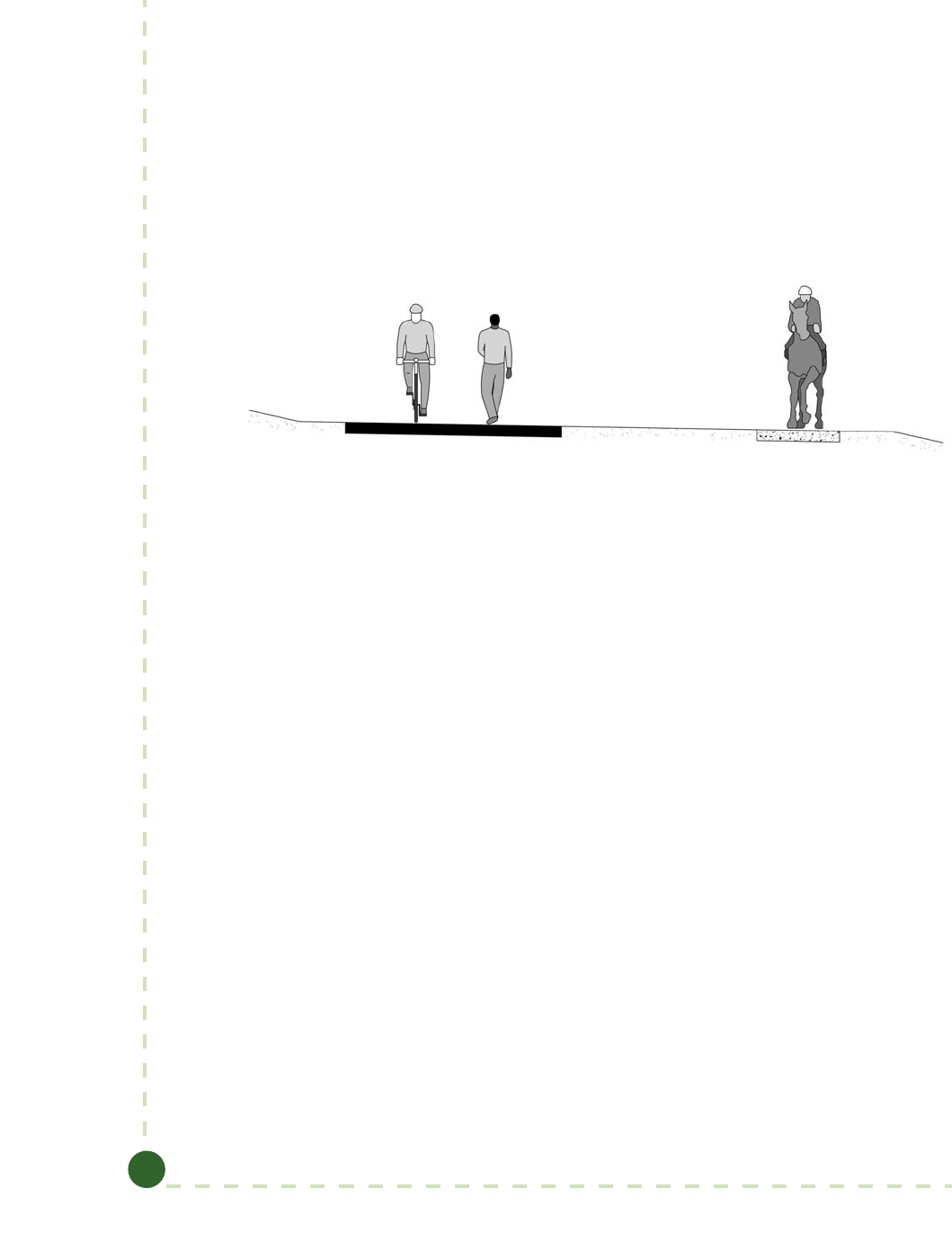
Guide to Bicycle Facilities, 4th Edition
5-12
Bicycling and equestrian use have successfully been integrated on many pathways in the United
States. However, care should be taken in designing these facilities to reduce potential conicts
between users. Bicyclists are often unaware of the need for slower speeds and additional clearance
around horses. Horses can be startled easily and may act unpredictably if they perceive approach-
ing bicyclists as a danger. Measures to mitigate bicyclist–equestrian conicts include provision of
separate bridle paths, maintenance of adequate sight lines so that bicyclists and equestrians are
able to see each other well in advance, and signing that claries appropriate passing techniques
and yielding responsibilities. Along paths with high- to moderate-use, the separate paved and
unpaved treads should be divided by at least a 6-ft (1.8-m) wide vegetation buer or barrier.
Consideration can also be given to providing an elevation change between the treads (15). Where
used, a separate, unpaved bridle path can often serve a dual purpose, as many joggers also prefer
unpaved surfaces (see Figure 5-5).
Figure 5-5. Shared Use Path with Separate Unpaved Equestrian/Jogger Path
5.2.4 Design Speed
Design speed is a selected speed used to determine various geometric features of the shared use
path. Once the design speed is selected, all pertinent path features should be related to it to ob-
tain a balanced design. In most situations, shared use paths should be designed for a speed that is
at least as high as the preferred speed of the fastest common user. e speed a path user travels is
dependent on several factors, including the physical condition of the user; the type and condition
of the user’s equipment; the purpose and length of the trip; the condition, location, and grade of
the path; the prevailing wind speed and direction; and the number and types of other users on
the path.
ere is no single design speed that is recommended for all paths. When selecting an appropriate
design speed for a specic path, planners and designers should consider several factors including
the context of the path, the types of users expected, the terrain the path runs through, prevailing
winds, the path surface, and other path characteristics. e following examples help to illustrate
these factors:
 Types of Users and Context. An urban path with a variety of users and frequent
conicts and constraints may be designed for lower speeds than a rural path with few
conicts that is primarily used by recreational bicyclists (potentially including recum-
bent bicyclists, whose 85th percentile speed is 18 mph [29 km/h]).
 Terrain. A path in fairly hilly terrain should be designed for a higher speed.
 Path Surface. Bicyclists tend to ride slower on unpaved paths, so a lower design
speed may be used.
© 2012 by the American Association of State Highway and Transportation Officials.
All rights reserved. Duplication is a violation of applicable law.
Copyright American Association of State Highway and Transportation Officials
Provided by IHS under license with AASHTO
Licensee=Purdue University/5923082001
Not for Resale, 06/14/2012 21:55:46 MDT
No reproduction or networking permitted without license from IHS
--`,`,`,``,`,``,`````,```,`,```,-`-`,,`,,`,`,,`---

Chapter 5: Design of Shared Use Paths
5-13
In street and highway design, design speeds are generally selected in 5 mph or 10 km/h incre-
ments; which are based on the approximate 85th percentile speed range on various types of
roadways of 20 mph (30 km/h) to 75 mph (120 km/h) or higher. On paths, the range of speeds
is much smaller, ranging as low as 12 mph (19 km/h) to 30 mph (50 km/h). erefore, design
speeds for paths can be selected in 2 mph (3 km/h) increments. Design criteria for geometric
features in this document are provided in 2 mph (3 km/h) increments for the slower end of the
scale (design speeds between 12 mph [19 km/h] and 20 mph [32 km/h]). For design speeds above
20mph (32 km/h), 5 mph (8 km/h) increments are used.
e following guidance and the aforementioned consideration of various factors should guide the
selection of an appropriate design speed:
 For most paths in relatively at areas (grades less than 2 percent), a design speed of
18 mph (30 km/h) is generally sucient, except on inclines where higher speeds can
occur. e design speed should not be lower, except in rare circumstances where the
context and user types support a lower speed.
 In areas with hilly terrain and sustained steeper grades (6 percent or greater), the
appropriate design speed should be selected based on the anticipated travel speeds of
bicyclists going downhill. In all but the most extreme cases, 30 mph (48 km/h) is the
maximum design speed that should be used.
Lower speeds can reduce the likelihood for crashes at approaches to crossings or conict points by
allowing the path user to better perceive the crossing situation or potential conict. It is impor-
tant to give the bicyclist adequate warning (either through signs or by maintaining adequate sight
lines) prior to areas of the pathway where lower design speeds are employed. See Section 5.4.2 for
guidance on warning signs.
Geometric design and trac control devices can be used to reduce path users’ speed. Speeds can
be reduced by geometric features such as horizontal curvature. Eectiveness of speed control
through design is limited if bicyclists can veer o a path to “straighten out” curves, and speed
limit signs on paths may not be eective, as most bicyclists do not use speedometers.
5.2.5 Horizontal Alignment
e typical adult bicyclist is the design user for horizontal alignment. e minimum radius of
horizontal curvature for bicyclists can be calculated using two dierent methods. One method
uses “lean angle,” and the other method uses superelevation and coecient of friction. As detailed
below, in general, the lean angle method should be used in design, although there are situations
where the superelevation method is helpful.
Calculating Minimum Radius Using Lean Angle
Unlike an automobile, a bicyclist must lean while cornering to prevent falling outward due to
forces associated with turning movements. Most bicyclists usually do not lean drastically; 20
degrees is considered the typical maximum lean angle for most users (10). Assuming an operator
who sits straight in the seat, Table 5-1 shows an equation that can determine the minimum radius
of curvature for any given lean angle and design speed.
© 2012 by the American Association of State Highway and Transportation Officials.
All rights reserved. Duplication is a violation of applicable law.
Copyright American Association of State Highway and Transportation Officials
Provided by IHS under license with AASHTO
Licensee=Purdue University/5923082001
Not for Resale, 06/14/2012 21:55:46 MDT
No reproduction or networking permitted without license from IHS
--`,`,`,``,`,``,`````,```,`,```,-`-`,,`,,`,`,,`---

Guide to Bicycle Facilities, 4th Edition
5-14
Table 5-1. Minimum Radius of Curvature Based on Lean Angle
U.S. Customary Metric
θ
0.067
tan
2
V
R=
θ
0.0079
tan
2
V
R=
where: where:
R = minimum radius of
curvature (ft)
R = minimum radius of
curvature (m)
V = design speed (mph) V = design speed (km/h)
θ
= lean angle from the
vertical (degrees)
θ
= lean angle from the
vertical (degrees)
As described in Section 5.1.1, shared use paths should meet accessibility guidelines, which restrict
the steepness of cross slopes. One percent slopes are recommended on shared use paths where
practical, because they are easier to navigate for people using wheelchairs. In most cases the lean
angle formula should be used when determining the minimum radius of a horizontal curve, due
to the need for relatively at cross slopes and the fact that bicyclists lean when turning (regardless
of their speed or the radius of their turn). e curve radius should be based upon various design
speeds of 18 to 30 mph (29 to 48 km/h) and a desirable maximum lean angle of 20 degrees.
Lower design speeds of 12 to 16 mph (19 to 26 km/h) may be appropriate under some circum-
stances (e.g., where environmental or physical constraints limit the geometrics). Minimum radii
of curvature for a paved path can be selected from Table 5-2.
Table 5-2. Minimum Radii for Horizontal Curves on Paved, Shared Use Paths at 20-Degree Lean Angle
U.S. Customary Metric
Design Speed (mph) Minimum Radius (ft) Design Speed (km/h) Minimum Radius (m)
12 27 19 8
14 36 23 11
16 47 26 15
18 60 29 18
20 74 32 22
25 115 40 35
30 166 48 50
Calculating Minimum Radius Using Superelevation
e second method of calculating minimum radius of curvature negotiable by a bicycle uses
the design speed, the superelevation rate of the pathway surface, and the coecient of friction
between the bicycle tires and the surface, as shown in Table 5-3:
© 2012 by the American Association of State Highway and Transportation Officials.
All rights reserved. Duplication is a violation of applicable law.
Copyright American Association of State Highway and Transportation Officials
Provided by IHS under license with AASHTO
Licensee=Purdue University/5923082001
Not for Resale, 06/14/2012 21:55:46 MDT
No reproduction or networking permitted without license from IHS
--`,`,`,``,`,``,`````,```,`,```,-`-`,,`,,`,`,,`---

Chapter 5: Design of Shared Use Paths
5-15
Table 5-3. Minimum Radius of Curvature Based on Superelevation
U.S. Customary Metric
2
15
100
V
R=
e
+f
2
127
100
V
R=
e
+f
where: where:
R = minimum radius of
curvature (ft)
R = minimum radius of
curvature (m)
V = design speed (mph) V = design speed (km/h)
e = rate of bikeway superel-
evation (percent)
e = rate of bikeway superel-
evation (percent)
f = coefficient of friction f = coefficient of friction
e coecient of friction depends upon speed, surface type and condition, tire type and condi-
tion, and whether the surface is wet or dry. Friction factors used for design should be selected
based upon the point at which turning forces or perceived lack of surface traction causes the
bicyclist to recognize a feeling of discomfort and instinctively act to avoid higher speed. Extrapo-
lating from values used in highway design, design friction factors for paved shared use paths can
be assumed to vary from 0.34 at 6 mph (10 km/h) to 0.21 at 30 mph (48 km/h). On unpaved
surfaces, friction factors should be reduced by 50 percent to reduce the likelihood of crashes.
Calculating minimum radius based on superelevation may be useful on unpaved paths, where
bicyclists may be hesitant to lean as much while cornering due to the perceived lack of traction.
In these situations, the superelevation formula should be used with appropriate friction factors
for unpaved surfaces. Calculating minimum radius based on superelevation may also be useful on
paved paths intended for bicycle use only, allowing higher design speeds to be accommodated on
relatively sharp curves with cross slopes (superelevation) up to 8 percent.
When a radius is smaller than that needed for an 18 mph (29 km/h) design speed, standard turn
or curve warning signs (W1 series) should be installed in accordance with the MUTCD (7).
Smaller radius curves are typically used when there are constrained site conditions, topographic
challenges, or a desire to reduce path user speeds. e negative eects of sharper curves can also
be partially oset by widening the pavement through the curves.
5.2.6 Cross Slope
As previously described, shared use paths must be accessible to people with disabilities. Shared use
paths located adjacent to roadways essentially function as sidewalks, and therefore should follow
PROWAG (13), which requires that cross slopes not exceed 2 percent. Until the specic regula-
tions concerning shared use paths are completed (14), paths in independent rights-of-way should
be designed according to ANPRM on Shared Use Paths (12), which also requires that cross slopes
not exceed 2 percent. As described in the previous section, 1 percent cross slopes are recommend-
ed on shared use paths, to better accommodate people with disabilities and to provide enough
slope to convey surface drainage in most situations. A cross-section that provides a center crown
with no more than 1 percent in each direction may also be used.
© 2012 by the American Association of State Highway and Transportation Officials.
All rights reserved. Duplication is a violation of applicable law.
Copyright American Association of State Highway and Transportation Officials
Provided by IHS under license with AASHTO
Licensee=Purdue University/5923082001
Not for Resale, 06/14/2012 21:55:46 MDT
No reproduction or networking permitted without license from IHS
--`,`,`,``,`,``,`````,```,`,```,-`-`,,`,,`,`,,`---

Guide to Bicycle Facilities, 4th Edition
5-16
Because this guide recommends a relatively at cross slope of 1 percent, and because horizontal
curvature can be based on a 20-degree lean angle, superelevation for horizontal curvature is not
needed. Since superelevation is not needed for horizontal curvature, cross slopes can follow the
direction of the existing terrain. is practice enables the designer to better accommodate surface
drainage and lessen construction impacts.
If cross slopes steeper than 2 percent are needed, they should be sloped to the inside of horizontal
curves regardless of drainage conditions. Steeper cross slopes (up to 5 percent) may occasionally
be desirable on unpaved shared use paths to reduce the likelihood of puddles caused by sur-
face irregularities and to allow increased superelevation to achieve smaller radii of curvature, as
previously described in the subsection on horizontal alignment. In rare situations where a path
is intended for bicycle use only (e.g., pedestrians are accommodated on a separate pathway) and
does not need to meet accessibility guidelines, cross slopes between 5 and 8 percent can be used
to allow for smaller minimum horizontal curve radii, as discussed above.
Cross slopes should be transitioned to connect to existing slopes, or to adjust to a reversal of
predominant terrain slope or drainage, or to a horizontal curve in some situations. Cross slope
transitions should be comfortable for the path user. A minimum transition length of 5 ft (1.5m)
for each 1 percent change in cross slope should be used.
5.2.7 Grade
e maximum grade of a shared use path adjacent to a roadway should be 5 percent, but the
grade should generally match the grade of the adjacent roadway. Where a shared use path runs
along a roadway with a grade that exceeds 5 percent, the sidepath grade may exceed 5 percent
but must be less than or equal to the roadway grade. Grades on shared use paths in independent
rights-of-way should be kept to a minimum, especially on long inclines. Grades steeper than 5
percent are undesirable because the ascents are dicult for many path users, and the descents
cause some users to exceed the speeds at which they are competent or comfortable. In addition,
because shared use paths are generally open to pedestrians, the allowable grades on paths
are subject to the accessibility guidelines described in the ANPRM on Shared Use Paths (12).
Grades on paths in independent rights-of-way should also be limited to 5 percent maximum.
e ANPRM suggests that certain conditions such as physical constraints (existing terrain or
infrastructure, notable natural features, etc.) or regulatory constraints (endangered species, the
environment, etc.) may prevent full compliance with the 5 percent maximum grade. Refer to
the U.S. Access Board website (www.access-board.gov) for up-to-date information regarding the
accessibility provisions for shared-use paths covered by the Americans with Disabilities Act and
the Architectural Barriers Act.
Options to mitigate excessive grades on shared use pathways include the following:
 Use higher design speeds for horizontal and vertical curvature, stopping sight
distance, and other geometric features.
 When using a longer grade, consider an additional 4 to 6 ft (1.2 to 1.8 m) of width
to permit slower bicyclists to dismount and walk uphill, and to provide more maneu-
vering space for fast downhill bicyclists.
 Install the hill warning sign for bicyclists (W7-5) and advisory speed plaque, if
appropriate, per the MUTCD (7).
© 2012 by the American Association of State Highway and Transportation Officials.
All rights reserved. Duplication is a violation of applicable law.
Copyright American Association of State Highway and Transportation Officials
Provided by IHS under license with AASHTO
Licensee=Purdue University/5923082001
Not for Resale, 06/14/2012 21:55:46 MDT
No reproduction or networking permitted without license from IHS
--`,`,`,``,`,``,`````,```,`,```,-`-`,,`,,`,`,,`---

Chapter 5: Design of Shared Use Paths
5-17
 Provide signing that alerts path users to the maximum percent of grade as shown in
the MUTCD (7).
 Exceed minimum horizontal clearances, recovery area, and/or protective railings.
 If other designs are not practicable, use a series of short switchbacks to traverse the
grade. If this is done, an extra 4 to 6 ft (1.2 to 1.8 m) of path width is recommended
to provide maneuvering space.
 Provide resting intervals with atter grades, to permit users to stop periodically
and rest.
Grades steeper than 3 percent may not be practical for shared use paths with crushed stone or
other unpaved surfaces for both bicycle handling and drainage erosion reasons. Typically, grades
less than 0.5 percent should be avoided, because they are not ecient in conveying surface drain-
age. Where paths are built in very at terrain, proposed path grades can be increased to provide a
gradually rolling vertical prole that helps convey surface drainage to outlet locations.
5.2.8 Stopping Sight Distance
To provide path users with opportunities to see and react to unexpected conditions, shared use
paths should be designed with adequate stopping sight distances. e distance needed to bring
a path user to a fully controlled stop is a function of the user’s perception and braking reaction
times, the initial speed, the coecient of friction between the wheels and the pavement, the
braking ability of the user’s equipment, and the grade. e coecient of friction for the typical
bicyclist is 0.32 for dry conditions. Figures 5-6 and 5-7 indicates the minimum stopping sight
distance for various design speeds and grades based on a total perception and brake reaction time
of 2.5 seconds and a coecient of friction of 0.16 (Table 5-4), appropriate for wet conditions.
Minimum stopping sight distance can also be calculated using the equation shown in Table 5-4.
Table 5-4. Minimum Stopping Sight Distance
U.S. Customary Metric
( )
2
3.67
30
V
S= + V
f±G
( )
2
254
VV
S= +
f±G 1.4
where: where:
S = stopping sight distance (ft) S = stopping sight distance (m)
V = velocity (mph) V = velocity (km/h)
f = coefficient of friction (use 0.16
for a typical bike)
f = coefficient of friction (use 0.16
for a typical bike)
G = grade (ft/ft) (rise/run) G = grade (m/m) (rise/run)
© 2012 by the American Association of State Highway and Transportation Officials.
All rights reserved. Duplication is a violation of applicable law.
Copyright American Association of State Highway and Transportation Officials
Provided by IHS under license with AASHTO
Licensee=Purdue University/5923082001
Not for Resale, 06/14/2012 21:55:46 MDT
No reproduction or networking permitted without license from IHS
--`,`,`,``,`,``,`````,```,`,```,-`-`,,`,,`,`,,`---

Guide to Bicycle Facilities, 4th Edition
5-18
Figure 5-6. Minimum Stopping Sight Distance vs. Grades for Various Design Speeds—Ascending
Climbing Grade
© 2012 by the American Association of State Highway and Transportation Officials.
All rights reserved. Duplication is a violation of applicable law.
Copyright American Association of State Highway and Transportation Officials
Provided by IHS under license with AASHTO
Licensee=Purdue University/5923082001
Not for Resale, 06/14/2012 21:55:46 MDT
No reproduction or networking permitted without license from IHS
--`,`,`,``,`,``,`````,```,`,```,-`-`,,`,,`,`,,`---

Chapter 5: Design of Shared Use Paths
5-19
Figure 5-7. Minimum Stopping Sight Distance vs. Grades for Various Design
Speeds—Descending Climbing Grade
© 2012 by the American Association of State Highway and Transportation Officials.
All rights reserved. Duplication is a violation of applicable law.
Copyright American Association of State Highway and Transportation Officials
Provided by IHS under license with AASHTO
Licensee=Purdue University/5923082001
Not for Resale, 06/14/2012 21:55:46 MDT
No reproduction or networking permitted without license from IHS
--`,`,`,``,`,``,`````,```,`,```,-`-`,,`,,`,`,,`---

Guide to Bicycle Facilities, 4th Edition
5-20
Research indicates that, under dry conditions, the coecient of friction of various other path us-
ers range from 0.20 for inline skaters to 0.30 for recumbent bicyclists. If users with lower coe-
cients of friction such as inline skaters or recumbent bicyclists are expected to make up a relatively
large percentage of path users, stopping sight distances should be increased. For two-way shared
use paths, the sight distance in the descending direction, that is, where “G” is dened as negative,
will control the design.
Figure 5-8 is used to select the minimum length of vertical curve needed to provide minimum
stopping sight distance at various speeds on crest vertical curves. e eye height of the typi-
cal adult bicyclist is assumed to be 4.5 ft (1.4 m), and the object height is assumed to be 0 in.
(0 mm) to recognize that impediments to bicycle travel exist at pavement level. e minimum
length of vertical curve can also be calculated using the following equation as shown in Table 5-5.
Table 5-5. Length of Crest Vertical Curve to Provide Sight Distance
U.S. Customary Metric
( )
( )
200
2
2
100
S < L L = S –
A
AS
S < L L = S –
2
12
2
2
12
h+ h
2h + 2h
( )
( )
200
2
2
100
S < L L = S –
A
AS
S < L L = S –
2
12
2
2
12
h+ h
2h + 2h
where: where:
L = minimum length of vertical
curve (ft)
L = minimum length of vertical
curve (m)
A = algebraic grade difference
(percent)
A = algebraic grade difference
(percent)
S = stopping sight distance (ft) S = stopping sight distance (m)
h
1
= eye height (4.5 ft for a typical
bicyclist)
h
1
= eye height (1.4 m for a typical
bicyclist)
h
2
= object height (0 ft) h
2
= object height (0 m)
© 2012 by the American Association of State Highway and Transportation Officials.
All rights reserved. Duplication is a violation of applicable law.
Copyright American Association of State Highway and Transportation Officials
Provided by IHS under license with AASHTO
Licensee=Purdue University/5923082001
Not for Resale, 06/14/2012 21:55:46 MDT
No reproduction or networking permitted without license from IHS
--`,`,`,``,`,``,`````,```,`,```,-`-`,,`,,`,`,,`---

Chapter 5: Design of Shared Use Paths
5-21
U.S. Customary
A S = Stopping Sight Distance (ft)
(%) 20 40 60 80 100 120 140 160 180 200 220 240 260 280 300
2 30 70 110 150
3 20 60 100 140 180 220 260 300
4 15 55 95 135 175 215 256 300 348 400
5 20 60 100 140 180 222 269 320 376 436 500
6 10 50 90 130 170 210 267 323 384 451 523 600
7 31 71 111 151 191 231 311 376 448 526 610 700
8 8 48 88 128 168 208 248 356 430 512 601 697 800
9 20 60 100 140 180 220 260 400 484 576 676 784 900
10 30 70 110 150 190 230 270 444 538 640 751 871 1000
11 38 78 118 158 198 238 278 489 592 704 826 958 1100
12 5 45 85 125 165 205 245 285 533 645 768 901 1045 1200
13 11 51 91 131 171 211 251 291 578 699 832 976 1132 1300
14 16 56 96 136 176 216 256 296 622 753 896 1052 1220 1400
15 20 60 100 140 180 220 260 300 667 807 960 1127 1307 1500
16 24 64 104 144 184 224 264 304 711 860 1024 1202 1394 1600
17 27 67 107 147 187 227 267 307 756 914 1088 1277 1481 1700
18 30 70 110 150 190 230 270 310 800 968 1152 1352 1568 1800
19 33 73 113 153 193 233 273 313 844 1022 1216 1427 1655 1900
20 35 75 115 155 195 235 275 315 889 1076 1280 1502 1742 2000
21 37 77 117 157 197 237 277 317 933 1129 1344 1577 1829 2100
22 39 79 119 159 199 239 279 319 978 1183 1408 1652 1916 2200
23 41 81 121 161 201 241 281 321 1022 1237 1472 1728 2004 2300
24 3 43 83 123 163 203 243 283 323 1067 1291 1536 1803 2091 2400
25 4 44 84 124 164 204 244 284 324 1111 1344 1600 1878 2178 2500
Shaded area represents S = L
Minimum length of vertical curve = 3 ft
Figure 5-8. Minimum Length of Crest Vertical Curve Based on Stopping Sight Distance
© 2012 by the American Association of State Highway and Transportation Officials.
All rights reserved. Duplication is a violation of applicable law.
Copyright American Association of State Highway and Transportation Officials
Provided by IHS under license with AASHTO
Licensee=Purdue University/5923082001
Not for Resale, 06/14/2012 21:55:46 MDT
No reproduction or networking permitted without license from IHS
--`,`,`,``,`,``,`````,```,`,```,-`-`,,`,,`,`,,`---

Guide to Bicycle Facilities, 4th Edition
5-22
Metric
A S = Stopping Sight Distance (m)
(%) 10 15 20 25 30 35 40 45 50 55 60 65 70 75 80 85 90 95 100
2 10 20 30 40 50 60
3 7 17 27 37 47 57 67 77 87 97 107
4 0 10 20 30 40 50 60 70 80 91 103 116 129 143
5 4 14 24 34 44 54 64 75 88 100 114 129 145 161 179
6 3 13 23 33 43 54 65 77 91 105 121 137 155 174 193 214
7 10 20 30 40 51 63 76 90 106 123 141 160 181 203 226 250
8 5 15 25 35 46 58 71 86 103 121 140 161 183 206 231 258 286
9 9 19 29 39 51 65 80 97 116 136 158 181 206 232 260 290 321
10 2 12 22 32 44 57 72 89 108 129 151 175 201 229 258 289 322 357
11 5 15 25 35 48 63 80 98 119 141 166 193 221 251 284 318 355 393
12 7 17 27 39 53 69 87 107 130 154 181 210 241 274 310 347 387 429
13 8 18 29 42 57 74 94 116 140 167 196 228 261 297 335 376 419 464
14 10 20 31 45 61 80 101 125 151 180 211 245 281 320 361 405 451 500
15 1 11 21 33 48 66 86 108 134 162 193 226 263 301 343 387 434 483 536
16 3 13 23 36 51 70 91 116 143 173 206 241 280 321 366 413 463 516 571
17 4 14 24 38 55 74 97 123 152 184 219 257 298 342 389 439 492 548 607
18 4 14 26 40 58 79 103 130 161 194 231 272 315 362 411 464 521 580 643
19 5 15 27 42 61 83 109 137 170 205 244 287 333 382 434 490 550 612 679
20 6 16 29 45 64 88 114 145 179 216 257 302 350 402 457 516 579 645 714
21 7 17 30 47 68 92 120 152 188 227 270 317 368 422 480 542 608 677 750
22 7 18 31 49 71 96 126 159 196 238 283 332 385 442 503 568 636 709 786
23 8 18 33 51 74 101 131 166 205 248 296 347 403 462 526 593 665 741 821
24 8 19 34 54 77 105 137 174 214 259 309 362 420 482 549 619 694 774 857
25 9 20 36 56 80 109 143 181 223 270 321 377 438 502 571 645 723 806 893
Shaded area represents S = L
Minimum length of vertical curve = 1 m
Figure 5-8. Minimum Length of Crest Vertical Curve Based on Stopping Sight Distance (continued)
Other path users such as child bicyclists, hand bicyclists, recumbent bicyclists, and others have
lower eye heights than a typical adult bicyclist. Eye heights are approximately 2.6 ft (0.85 m) for
hand bicyclists and 3.9 ft (1.2 m) for recumbent bicyclists. When compared to the eye heights of
typical bicyclists, these lower eye heights limit sight distance over crest vertical curves. However,
since most hand bicyclists and child bicyclists travel slower than typical adult bicyclists, their
needs are met by using the values in Figure 5-8. Recumbent bicyclists generally travel faster than
typical upright bicyclists, so if they are expected to make up a relatively large percentage of path
users, crest vertical curve lengths should be increased accordingly (operating characteristics of
recumbent bicyclists are found in Chapter 3).
Figures 5-9, 5-10, and Table 5-6 indicate the minimum clearance that should be used for line-of-
sight obstructions for horizontal curves. e lateral clearance (horizontal sight line oset or HSO)
is obtained by using the table in Figure 5-9 with the stopping sight distance (Figure 5-6) and the
proposed horizontal radius of curvature.
Path users typically travel side-by-side on shared use paths. On narrow paths, bicyclists have a
tendency to ride near the middle of the path. For these reasons, and because of the higher likeli-
© 2012 by the American Association of State Highway and Transportation Officials.
All rights reserved. Duplication is a violation of applicable law.
Copyright American Association of State Highway and Transportation Officials
Provided by IHS under license with AASHTO
Licensee=Purdue University/5923082001
Not for Resale, 06/14/2012 21:55:46 MDT
No reproduction or networking permitted without license from IHS
--`,`,`,``,`,``,`````,```,`,```,-`-`,,`,,`,`,,`---

Chapter 5: Design of Shared Use Paths
5-23
hood for crashes on curves, lateral clearances on horizontal curves should be calculated based on
the sum of the stopping sight distances for path users traveling in opposite directions around the
curve. Where this is not practical, consideration should be given to widening the path through
the curve, installing a yellow center line stripe, installing turn or curve warning signs (W1 series)
in accordance with the MUTCD (7), or a combination of these alternatives. See Sections 5.4.1
and 5.4.2 for more information about center line pavement markings and signs.
Figure 5-9. Diagram Illustrating Components for Determining Horizontal Sight Distance
Table 5-6. Horizontal Sight Distance
U.S. Customary Metric
–
–
−
−
1
28.65
1
1
28.65
S
H S O = R
R
R R HSO
H SO =
R
cos
cos
–
–
−
−
1
28.65
1
1
28.65
S
H S O = R
R
R R HSO
H SO =
R
cos
cos
where: where:
S = stopping sight distance (ft) S = stopping sight distance (m)
R = radius of centerline of lane (ft) R = radius of centerline of lane (m)
HSO = horizontal sightline offset,
distance from centerline of
lane to obstruction (ft)
HSO = horizontal sightline offset,
distance from centerline of lane
to obstruction (m)
Note: Angle is expressed in degrees; line of sight is 2.3 ft above
centerline of inside lane at point of obstruction.
Note: Angle is expressed in degrees; line of sight is 0.7 m above
centerline of inside lane at point of obstruction.
© 2012 by the American Association of State Highway and Transportation Officials.
All rights reserved. Duplication is a violation of applicable law.
Copyright American Association of State Highway and Transportation Officials
Provided by IHS under license with AASHTO
Licensee=Purdue University/5923082001
Not for Resale, 06/14/2012 21:55:46 MDT
No reproduction or networking permitted without license from IHS
--`,`,`,``,`,``,`````,```,`,```,-`-`,,`,,`,`,,`---

Guide to Bicycle Facilities, 4th Edition
5-24
U.S. Customary
S = Stopping Sight Distance (ft)
R
(ft)
20 40 60 80 100 120 140 160 180 200 220 240 260 280 300
25 2.0 7.6 15.9
50 1.0 3.9 8.7 15.2 23.0 31.9 41.5
75 0.7 2.7 5.9 10.4 16.1 22.8 30.4 38.8 47.8 57.4 67.2
95 0.5 2.1 4.7 8.3 12.9 18.3 24.7 31.8 39.5 48.0 56.9 66.3 75.9 85.8
125 0.4 1.6 3.6 6.3 9.9 14.1 19.1 24.7 31.0 37.9 45.4 53.3 61.7 70.6 79.7
155 0.3 1.3 2.9 5.1 8.0 11.5 15.5 20.2 25.4 31.2 37.4 44.2 51.4 59.1 67.1
175 0.3 1.1 2.6 4.6 7.1 10.2 13.8 18.0 22.6 27.8 33.5 39.6 46.1 53.1 60.5
200 0.3 1.0 2.2 4.0 6.2 8.9 12.1 15.8 19.9 24.5 29.5 34.9 40.8 47.0 53.7
225 0.2 0.9 2.0 3.5 5.5 8.0 10.8 14.1 17.8 21.9 26.4 31.3 36.5 42.2 48.2
250 0.2 0.8 1.8 3.2 5.0 7.2 9.7 12.7 16.0 19.7 23.8 28.3 33.1 38.2 43.7
275 0.2 0.7 1.6 2.9 4.5 6.5 8.9 11.6 14.6 18.0 21.7 25.8 30.2 34.9 39.9
300 0.2 0.7 1.5 2.7 4.2 6.0 8.1 10.6 13.4 16.5 19.9 23.7 27.7 32.1 36.7
350 0.1 0.6 1.3 2.3 3.6 5.1 7.0 9.1 11.5 14.2 17.1 20.4 23.9 27.6 31.7
390 0.1 0.5 1.2 2.1 3.2 4.6 6.3 8.2 10.3 12.8 15.4 18.3 21.5 24.9 28.5
500 0.1 0.4 0.9 1.6 2.5 3.6 4.9 6.4 8.1 10.0 12.1 14.3 16.8 19.5 22.3
565 0.4 0.8 1.4 2.2 3.2 4.3 5.7 7.2 8.8 10.7 12.7 14.9 17.3 19.8
600 0.3 0.8 1.3 2.1 3.0 4.1 5.3 6.7 8.3 10.1 12.0 14.0 16.3 18.7
700 0.3 0.6 1.1 1.8 2.6 3.5 4.6 5.8 7.1 8.6 10.3 12.0 14.0 16.0
800 0.3 0.6 1.0 1.6 2.2 3.1 4.0 5.1 6.2 7.6 9.0 10.5 12.2 14.0
900 0.2 0.5 0.9 1.4 2.0 2.7 3.6 4.5 5.6 6.7 8.0 9.4 10.9 12.5
1000 0.2 0.5 0.8 1.3 1.8 2.4 3.2 4.0 5.0 6.0 7.2 8.4 9.8 11.2
Metric
S = Stopping Sight Distance (m)
R
(m)
10 15 20 25 30 35 40 45 50 55 60 65 70 75 80 85 90 95 100
10 1.2 2.7 4.6 6.8 9.3
15 0.8 1.8 3.2 4.9 6.9 9.1 11.0 14.0
20 0.6 1.4 2.4 3.8 5.4 7.2 9.2 11.0 14.0 16.0 19.0
25 0.5 1.1 2.0 3.1 4.4 5.9 7.6 9.5 11.0 14.0 16.0 18.0 21.0 23.0
50 0.3 0.6 1.0 1.6 2.2 3.0 3.9 5.0 6.1 7.4 8.7 10.0 12.0 13.0 15.0 17.0 19.0 21.0 23.0
75 0.2 0.4 0.7 1.0 1.5 2.0 2.7 3.4 4.1 5.0 5.9 6.9 8.0 9.2 10.0 12.0 13.0 15.0 16.0
100 0.1 0.3 0.5 0.8 1.1 1.5 2.0 2.5 3.1 3.8 4.5 5.2 6.1 7.0 7.9 8.9 10.0 11.0 12.0
125 0.1 0.2 0.4 0.6 0.9 1.2 1.6 2.0 2.5 3.0 3.6 4.2 4.9 5.6 6.3 7.2 8.0 8.9 9.9
150 0.2 0.3 0.5 0.7 1.0 1.3 1.7 2.1 2.5 3.0 3.5 4.1 4.7 5.3 6.0 6.7 7.5 8.3
175 0.2 0.3 0.4 0.6 0.9 1.1 1.4 1.8 2.2 2.6 3.0 3.5 4.0 4.6 5.1 5.8 6.4 7.1
200 0.1 0.3 0.4 0.6 0.8 1.0 1.3 1.6 1.9 2.2 2.6 3.1 3.5 4.0 4.5 5.0 5.6 6.2
225 0.1 0.2 0.3 0.5 0.7 0.9 1.1 1.4 1.7 2.0 2.3 2.7 3.1 3.5 4.0 4.5 5.0 5.5
250 0.1 0.2 0.3 0.5 0.6 0.8 1.0 1.2 1.5 1.8 2.1 2.4 2.8 3.2 3.6 4.0 4.5 5.0
275 0.1 0.2 0.3 0.4 0.6 0.7 0.9 1.1 1.4 1.6 1.9 2.2 2.6 2.9 3.3 3.7 4.1 4.5
300 0.2 0.3 0.4 0.5 0.7 0.8 1.0 1.3 1.5 1.8 2.0 2.3 2.7 3.0 3.4 3.8 4.2
Figure 5-10. Minimum Lateral Clearance (Horizontal Sightline Offset or HSO) for Horizontal Curves
© 2012 by the American Association of State Highway and Transportation Officials.
All rights reserved. Duplication is a violation of applicable law.
Copyright American Association of State Highway and Transportation Officials
Provided by IHS under license with AASHTO
Licensee=Purdue University/5923082001
Not for Resale, 06/14/2012 21:55:46 MDT
No reproduction or networking permitted without license from IHS
--`,`,`,``,`,``,`````,```,`,```,-`-`,,`,,`,`,,`---

Chapter 5: Design of Shared Use Paths
5-25
5.2.9 Surface Structure
Hard, all-weather pavement surfaces are generally preferred over those of crushed aggregate,
sand, clay, or stabilized earth. Since unpaved surfaces provide a lower level of service, it may cause
bicyclists to more easily lose traction (particularly bicycles with narrower, higher-pressure tires),
and may need more maintenance. On unpaved surfaces, bicyclists and other wheeled users must
use a greater eort to travel at a given speed when compared to a paved surface. Some users, such
as inline skaters, are unable to use unpaved paths. In areas that experience frequent or even oc-
casional ooding or drainage problems, or in areas of moderate or steep terrain, unpaved surfaces
will often erode and are not recommended. Additionally, unpaved paths are dicult to plow for
use during the winter.
Unpaved surfaces may be appropriate on rural paths, where the intended use of the path is
primarily recreational, or as a temporary measure to open a path before funding is available for
paving. Unpaved pathways should be constructed of materials that are rm and stable. Possible
surfaces for unpaved paths include crushed stone, stabilized earth, and limestone screenings,
depending upon local availability.
Asphalt or Portland cement concrete provides good quality, all-weather pavement structures. Ad-
vantages of Portland cement concrete include longer service life, reduced susceptibility to crack-
ing and deformation from roots and weeds, and a more consistent riding surface after years of use
and exposure to the elements. On Portland cement concrete pavements, transverse joints can be
cut with a saw to provide a smooth ride. A disadvantage of Portland cement concrete pavements
is that pavement markings (such as centerlines) can have a lower contrast against the concrete
surface; markings typically have a higher contrast on an asphalt surface, particularly at night.
Advantages of asphalt include a smooth rolled surface when new, and lower construction costs
than with concrete. Asphalt surfaces are softer and are therefore preferred by runners and walkers
over concrete. However, asphalt pavement is less durable (typical life expectancy is 15–20 years)
and needs more interim maintenance.
Because of wide variations in soils, loads, materials, and construction practices, and varying costs
of pavement materials, it is not practical to recommend typical structural sections that will be ap-
plicable nationwide. However, the total pavement depth should typically be a minimum of 6in.
(150 mm), inclusive of the surface course (asphalt or Portland cement concrete) and the base
course (typically an aggregate rock base). Any pavement section should be placed over a com-
pacted subgrade.
Designing and selecting pavement sections for shared use paths is similar to designing and
selecting highway pavement sections. A soils investigation should be conducted to determine the
load-carrying capabilities of the native soil, or former railroad bed (if ballast has been removed),
and the need for any special treatments. A soils investigation should also be conducted to deter-
mine whether subsurface drainage may be applicable. In colder climates, the eects of freeze-thaw
cycles should be anticipated. Geotextiles and other similar materials should be considered where
subsurface conditions warrant, such as in locations with swelling clay subgrade. Experience in
roadway pavement design, together with sound engineering judgment, can assist in the selection
and design of a proper path pavement structure and may identify energy-conserving practices,
such as the use of sulfur-extended asphalt, asphalt emulsions, porous pavement, and recycled
asphalt.
© 2012 by the American Association of State Highway and Transportation Officials.
All rights reserved. Duplication is a violation of applicable law.
Copyright American Association of State Highway and Transportation Officials
Provided by IHS under license with AASHTO
Licensee=Purdue University/5923082001
Not for Resale, 06/14/2012 21:55:46 MDT
No reproduction or networking permitted without license from IHS
--`,`,`,``,`,``,`````,```,`,```,-`-`,,`,,`,`,,`---

Guide to Bicycle Facilities, 4th Edition
5-26
While loads on shared use paths will be substantially less than roadways, paths should be designed
to sustain wheel loads of occasional emergency, patrol, maintenance, and other motor vehicles
that are expected to use or cross the path. When motor vehicles are driven on shared use paths,
their wheels often will be at, or very near, the edges of the path. is can cause edge damage that,
in turn, will reduce the eective operating width of the path. e path should, therefore, be con-
structed of sucient width to accommodate the vehicles, and adequate edge support should be
provided. Edge support can be provided by means of stabilized shoulders, ush or raised concrete
curbing, or additional pavement width or thickness. e use of ush concrete curbing has other
long-term maintenance benets, such as reducing the potential for encroachment of vegetation
onto the path surface. If raised curbs are used, one foot of additional path width should be pro-
vided, as users will shy away from the curb, resulting in a narrower eective path width.
It is important to construct and maintain a smooth riding surface on shared use paths. Pavements
should be machine laid; soil sterilizers should be used where needed to prevent vegetation from
erupting through the pavement. On Portland cement concrete pavements, the transverse joints
needed to control cracking should be saw cut, rather than tooled, to provide a smoother ride.
On the other hand, skid resistance qualities should not be sacriced for the sake of smoothness.
Broom nish or burlap drag concrete surfaces are preferred.
Utility covers (i.e., manholes) and bicycle-compatible drainage grates should be ush with the
surface of the pavement on all sides. Preferably, manhole covers and drainage grates would be
located to the side of the paths so when work needs to be performed, the path would not need to
be closed. Railroad crossings should be smooth and be designed at an angle between 60 and 90
degrees to the direction of travel in order to minimize the possibility of falls. Refer to Chapter 4
for design treatments that can be used to improve railroad crossings.
Where a shared use path crosses an unpaved road or driveway, the road or driveway should be
paved a minimum of 20 ft (6 m) on each side of the crossing to reduce the amount of gravel scat-
tered onto or along the path by motor vehicles. e pavement structure at the crossing should be
adequate to sustain the expected loading at that location.
5.2.10 Bridges and Underpasses
A bridge or underpass may be needed to provide continuity to a shared use path. e “receiv-
ing” clear width on the end of a bridge (from inside of rail or barrier to inside of opposite rail or
barrier) should allow 2 ft (0.6 m) of clearance on each side of the pathway, as recommended in
Section 5.2.1, but under constrained conditions may taper to the pathway width.
Carrying the clear areas across the structures has two advantages. First, the clear width provides a
minimum horizontal shy distance from the railing or barrier, and second, it provides needed ma-
neuvering space to avoid conicts with pedestrians or bicyclists who have stopped on the bridge
(e.g., to admire the view).
Access by emergency, patrol, and maintenance vehicles should be considered in establishing
design clearances of structures on shared use paths. Similarly, vertical clearance may be dictated
by occasional authorized motor vehicles using the path. A minimum vertical clearance of 10 ft
(3.0m) is desirable for adequate vertical shy distance.
At transitions and approaches from paths to bridge decks, the height of the path’s surface should
match the height of the bridge deck surface so as to provide a smooth transition between path-
© 2012 by the American Association of State Highway and Transportation Officials.
All rights reserved. Duplication is a violation of applicable law.
Copyright American Association of State Highway and Transportation Officials
Provided by IHS under license with AASHTO
Licensee=Purdue University/5923082001
Not for Resale, 06/14/2012 21:55:46 MDT
No reproduction or networking permitted without license from IHS
--`,`,`,``,`,``,`````,```,`,```,-`-`,,`,,`,`,,`---

Chapter 5: Design of Shared Use Paths
5-27
way and bridge deck. Bridge deck lips, formed by dierences between pathway and bridge
deck heights, should be avoided because they can cause tire blowouts, bent wheels, crashes, and
injuries. ese lips can be eliminated by placing a transitional layer of asphalt between the path
surface and the bridge deck.
Where grade separation is desired between a path and a roadway or railroad, designers sometimes
have the choice between constructing a bridge over the roadway or railroad, and constructing
a tunnel or underpass under the roadway or railroad. e adjacent topography typically is the
greatest factor in determining which option is best; however, bridges are preferred to underpasses
because they have security advantages and are less likely to have drainage problems.
When a bridge or underpass is built over a public right-of-way (such as a road), a connection
is often needed between the path and roadway; as this represents a potential access point for
pedestrians and bicyclists. is often involves signicant ramping or other means to provide an
accessible connection between the two.
Protective railings, fences, or barriers on either side of a shared use path on a stand-alone structure
should be a minimum of 42 in. (1.05 m) high. ere are some locations where a 48-in. (1.2m)
high railing should be considered in order to prevent bicyclists from falling over the railing during
a crash. is includes bridges or bridge approaches where high-speed, steep-angle (25degrees or
greater) impacts between a bicyclist and the railing may occur, such as at a curve at the foot of a
long, descending grade where the curve radius is less than that appropriate for the design speed or
anticipated speed.
Openings between horizontal or vertical members on railings should be small enough that a 6in.
(150 mm) sphere cannot pass through them in the lower 27 in. (0.7 m). For the portion of railing
that is higher than 27 in. (0.7 m), openings may be spaced such that an 8 in. (200 mm) sphere
cannot pass through them. is is done to prevent children from falling through the openings.
Where a bicyclist’s handlebar may come into contact with a railing or barrier, a smooth, wide rub-
rail may be installed at a height of about 36 in. (0.9 m) to 44 in. (1.1 m), to reduce the likelihood
that a bicyclist’s handlebar will be caught by the railing (see Figure 5-11).
Figure 5-11. Bridge Railing
© 2012 by the American Association of State Highway and Transportation Officials.
All rights reserved. Duplication is a violation of applicable law.
Copyright American Association of State Highway and Transportation Officials
Provided by IHS under license with AASHTO
Licensee=Purdue University/5923082001
Not for Resale, 06/14/2012 21:55:46 MDT
No reproduction or networking permitted without license from IHS
--`,`,`,``,`,``,`````,```,`,```,-`-`,,`,,`,`,,`---
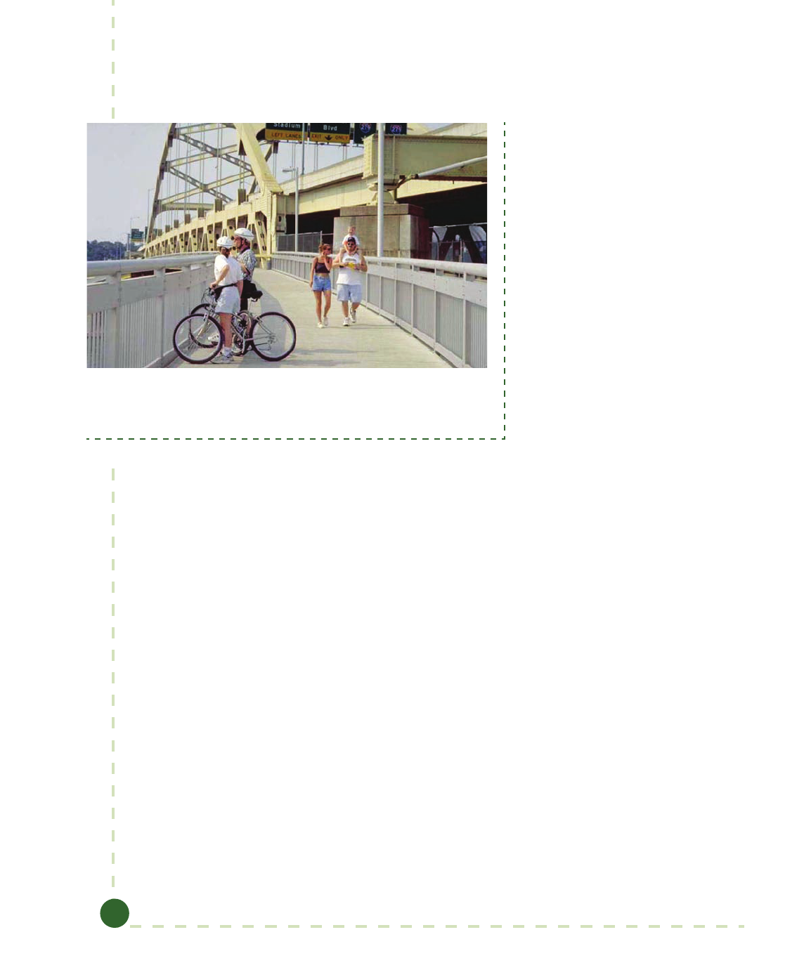
Guide to Bicycle Facilities, 4th Edition
5-28
Bridges should be designed for pedestrian live loadings. Where maintenance and emergency
vehicles may be expected to cross the bridge, the design should accommodate them. On all bridge
decks, special care should be taken that bicycle-compatible expansion joints are used, and that
decking materials are not slippery when wet. ere are often opportunities to retrot path struc-
tures to existing highway or railroad bridges. Using an existing bridge can result in signicant cost
savings and provide path continuity
over large rivers and other obstacles.
ese retrots can be accomplished
in several ways, including cantilever-
ing the path onto an existing bridge,
or by placing the path within the
substructure of the existing bridge, as
shown in Figure 5-12.
In many situations, there is a desire
to retrot a path under a bridge
along a river or waterway to provide
a grade-separated crossing of a major
road or railroad. Special treatments
may be needed in these circum-
stances. ese paths are often located
within a oodplain, so path pave-
ment and subgrade treatments may
need to be enhanced. In extreme
cases, paths can be built below the
normal water level, such that the
water would need to be retained
and a pumping system would need to be provided for the path. e structural design of bridges
for shared use paths (e.g., railings) should be designed in accordance with the AASHTO LRFD
Bridge Design Specications (1) and the Guide Specications for Design of Pedestrian Bridges (3). e
technical provisions in this manual either meet or exceed those recommended in the current ver-
sions of these respective specications.
5.2.11 Drainage
e minimum recommended pavement cross slope of 1 percent usually provides adequate drain-
age. Sloping in one direction instead of crowning is preferred and usually simplies drainage and
surface construction. An even surface is essential to prevent water ponding and ice formation. On
unpaved shared use paths, particular attention should be paid to drainage to avoid erosion.
Depending on site conditions, typically paths with cross slope in the direction of the existing ter-
rain will provide sheet ow of surface runo and avoid the need for channelizing ow in ditches,
cross culverts, and closed pipe systems. However, where a shared use path is constructed on the
side of a slope that has considerable runo, or other conditions that result in relatively high
runo, a ditch of suitable dimensions should be placed on the uphill side to intercept the slope’s
drainage. Such ditches should be designed so that the potential for injury to errant bicyclists
is limited. Where needed, catch basins with drains should be provided to carry the intercepted
water under the path. Bicycle-compatible drainage grates and manhole covers should be located
to the side of the pathway.
Figure 5-12. Example of Bridge Structures (Photo courtesy of Jennifer Toole
of Toole Design Group.)
© 2012 by the American Association of State Highway and Transportation Officials.
All rights reserved. Duplication is a violation of applicable law.
Copyright American Association of State Highway and Transportation Officials
Provided by IHS under license with AASHTO
Licensee=Purdue University/5923082001
Not for Resale, 06/14/2012 21:55:46 MDT
No reproduction or networking permitted without license from IHS
--`,`,`,``,`,``,`````,```,`,```,-`-`,,`,,`,`,,`---

Chapter 5: Design of Shared Use Paths
5-29
Paths that are located in low-lying areas may need attention to other drainage issues in the vicin-
ity that have not been previously addressed so that the path drains properly, and that retention
areas located away from the pathway are provided.
To prevent erosion in the area adjacent to the shared use path, consideration should be given to
preserving a hardy, natural ground cover. In addition, pathway design should meet applicable
storm water management regulations. In an eort to improve water quality and manage the
quantity of runo, low-impact development techniques such as bio-retention swales should be
considered. Other erosion and sediment control measures should be employed as needed, includ-
ing seeding, mulching, and sodding of adjacent slopes, swales, and other erodible areas.
5.2.12 Lighting
Fixed‐source lighting can improve visibility along paths and at intersections at night or under
other dark conditions. Lighting can also greatly improve riders’ ability to detect surface discon-
formities under such conditions, even when their bicycles are properly equipped with headlamps.
Provision of lighting should be considered where nighttime usage is not prohibited, and especially
on paths that provide convenient connections to transit stops and stations, schools, universities,
shopping, and employment areas.
Where nighttime use is permitted, pathway lighting is recommended at path–roadway intersec-
tions. If nighttime use is prohibited, lighting at crosswalks should still be considered if the path-
way connects to existing sidewalks, because the crossing is in the public right-of-way and may be
used at night even if the pathway is not. Lighting should also be considered in locations where
personal security is an issue.
Pedestrian-scale lighting is preferred to tall, highway-style lamps. Pedestrian-scale lighting is char-
acterized by shorter light poles (standards about 15 ft [4.6 m] high), lower levels of illumination
(except at crossings), closer spacing of standards (to avoid dark zones between luminaires), and
high pressure sodium vapor or metal halide lamps. Metal halide lamps produce better color rendi-
tion (“white light”) than sodium vapor lamps and can facilitate user recognition in areas with
high volumes of night use. Depending on the location, average maintained horizontal illumina-
tion levels of 0.5 to 2-foot candles (5 to 22 lux) should be considered. For personal safety, higher
lighting levels may be needed in some locations.
Placement of light poles should provide the recommended horizontal and vertical clearances from
the pathway. Light xtures should be chosen to reduce the loss of light and may need to comply
with local “dark sky” guidelines and regulations. e use of solar-powered lighting can be consid-
ered; however, care should be taken that the installation provides adequate light. Solar-powered
lighting is often inadequate in locations with signicant tree canopy, or in northern regions where
it sometimes fails to provide enough illumination during winter months.
If a pathway is used infrequently at night, lighting can be provided at certain hours only, based on
an engineering study of pathway usage; for example, up to 11:00 p.m. and starting at 6:00a.m.
ese conditions should be made known to path users with a sign at path entrances. Where
lighting is not provided, or only provided during certain hours, reective edge lines should be
provided as described in Section 5.4.1.
Lighting should be provided in pathway tunnels and underpasses. At night, lighting in tunnels
is important to provide security. Daytime lighting of tunnels and underpasses is often needed,
© 2012 by the American Association of State Highway and Transportation Officials.
All rights reserved. Duplication is a violation of applicable law.
Copyright American Association of State Highway and Transportation Officials
Provided by IHS under license with AASHTO
Licensee=Purdue University/5923082001
Not for Resale, 06/14/2012 21:55:46 MDT
No reproduction or networking permitted without license from IHS
--`,`,`,``,`,``,`````,```,`,```,-`-`,,`,,`,`,,`---

Guide to Bicycle Facilities, 4th Edition
5-30
and should be designed in a manner similar to the design of lighting in roadway tunnels. is
includes brighter lighting during the day than at night, due to the fact that users’ eyes cannot
make fast adjustments to changing light conditions. On long tunnels it is appropriate to use vary-
ing light intensities through the tunnel, with higher levels of illumination near the entrances and
lower levels in the middle. Refer to the Roadway Lighting Design Guide (5) for more information
about designing appropriate lighting in tunnels and underpasses.
5.3 SHARED USE PATH–ROADWAY INTERSECTION DESIGN
e design of intersections between shared use paths and roadways has a signicant impact on
users’ comfort and mobility. Intersection design should not only address cross-trac movements,
but should also address turning movements of riders entering and exiting the path. Due to poten-
tial conicts at these junctions, careful design should be used for predictable and orderly opera-
tion between shared use path trac and other trac.
Regardless of whether a pathway crosses a roadway at an existing intersection between two
roadways, or at a new “mid-block” location, the principles that apply to design for pedestrians at
crossings (controlled and uncontrolled) are also applicable to pathway–intersection design. ere
are a wide range of design features that have the likelihood to reduce pedestrian and bicyclist
crashes at such intersections. is guide provides a general overview of crossing measures; other
sources, such as AASHTO’s Guide for the Planning, Design, and Operation of Pedestrian Facilities
(2), should be consulted for more detail.
Shared use path crossings come in many congurations with many variables: the number of
roadway lanes to be crossed; divided or undivided roadways, number of approach legs; the speeds
and volumes of trac; and trac controls that range from uncontrolled to yield-, stop-, or signal-
controlled. Each intersection is unique and needs engineering judgment to determine an appro-
priate intersection treatment.
Due to the mixed nature of shared use path trac, the practitioner should keep in mind the
speed variability of each travel mode and its resulting eect on design values when considering
design treatments for path–roadway intersections. e fastest vehicle should be considered for
approach speeds (typically the bicyclist and motor vehicle) as these modes are the most likely to
surprise cross trac at the intersection. By contrast, for departures from a stopped condition,
the characteristics of slower path users (typically pedestrians) should be taken into account due
to their greater exposure to cross trac. Intersections between pathways and roadways should be
designed to be accessible to all users, as stated in Section 5.1.1.
5.3.1 Shared Use Path Crossing Types
Shared use path crossings can be broadly categorized as mid-block, sidepath, or grade-separated
crossings. A crossing is considered mid-block if it is located outside of the functional area of any
adjacent intersection. In some respects, a mid-block shared use path crossing can be considered
as a four-leg intersection. A sidepath crossing occurs within the functional area of an intersection
of two or more roadways (see Figure 5-13). Sidepath crossings are typically parallel to at least one
roadway. Sidepath intersections have unique operational challenges that are similar to those of
parallel frontage roadways. Section 5.2.2 covers these operational issues in detail.
© 2012 by the American Association of State Highway and Transportation Officials.
All rights reserved. Duplication is a violation of applicable law.
Copyright American Association of State Highway and Transportation Officials
Provided by IHS under license with AASHTO
Licensee=Purdue University/5923082001
Not for Resale, 06/14/2012 21:55:46 MDT
No reproduction or networking permitted without license from IHS
--`,`,`,``,`,``,`````,```,`,```,-`-`,,`,,`,`,,`---

Chapter 5: Design of Shared Use Paths
5-31
Figure 5-13. Mid-Block and Sidepath Crossings Relative to Intersection Functional Area
In some locations, roadway or path trac conditions may warrant consideration of a grade-
separated crossing consisting of either a bridge over the roadway or an underpass beneath the
roadway. An analysis should be made to assess the demand for and viability of a grade-separated
crossing. See Section 5.2.10 and the discussion of grade-separated crossings in the AASHTO
Guide for the Planning, Design, and Operation of Pedestrian Facilities (2).
5.3.2 Design of Mid-Block Crossings
e task of designing a mid-block crossing between a pathway and a roadway involves a number
of variables, including anticipated mix and volume of path users, the speed and volume of motor
vehicle trac on the roadway being crossed, the conguration of the road, the amount of sight
distance that can be achieved at the crossing location, and other factors. Geometric design fea-
tures and trac controls should be used in combination to eectively accommodate all users.
Geometric Design Issues at Crossings
e design approach for the intersection of a shared use path with a roadway is similar to the
design approach used for the intersection of two roadways in the following ways:
 e intersection should be conspicuous to both road users and path users.
 Sight lines should be maintained to meet the needs of the trac control provided.
 Intersections and approaches should be on relatively at grades.
 Intersections should be as close to a right angle as practical, given the existing
conditions.
© 2012 by the American Association of State Highway and Transportation Officials.
All rights reserved. Duplication is a violation of applicable law.
Copyright American Association of State Highway and Transportation Officials
Provided by IHS under license with AASHTO
Licensee=Purdue University/5923082001
Not for Resale, 06/14/2012 21:55:46 MDT
No reproduction or networking permitted without license from IHS
--`,`,`,``,`,``,`````,```,`,```,-`-`,,`,,`,`,,`---

Guide to Bicycle Facilities, 4th Edition
5-32
 e least trac control that is eective should be selected.
 Intersections should be suciently spaced to be outside the functional area of adja-
cent intersections (see Figure 5-13).
It is preferable for mid-block path crossings to intersect the roadway at an angle as close to
perpendicular as practical, so as to minimize the exposure of crossing path users and maximize
sight lines. A crossing skewed at 30 degrees is twice as long as a perpendicular crossing, doubling
the exposure of path users to approaching motor vehicles, and increasing delays for motorists
who must wait for path users to cross. Retrotting skewed path crossings can reduce the roadway
exposure for path users. Figure 5-14 depicts a path realignment to achieve a 90-degree crossing.
A minimum 60-degree crossing angle may be acceptable to minimize right-of-way needs (12).
Figure 5-14. Crossing Angle
Special Issues with Assignment of Right of Way
Shared use paths are unique in terms of the assignment of the right of way, due to the legal
responsibility of drivers to yield to (or stop for) pedestrians in crosswalks. Most state codes also
stipulate that a pedestrian may not suddenly leave any curb (or refuge area) and walk or run
into the path of a vehicle that is so close that it is impossible for the driver to yield. e result is
a mutual yielding responsibility among motor vehicle drivers and pedestrians, depending upon
the timing of their arrival at an intersection. Some states extend the rights and responsibilities of
pedestrians at crosswalks to bicyclists as well, while other states do not. When designing inter-
sections of shared use paths, designers should understand the laws within their state regarding
assignment of right of way for pedestrians and bicyclists (and other path users).
When assigning right of way, the speed dierential between bicyclists and pedestrians on the
pathway should also be taken into account. Bicyclists approach the intersection at a far greater
speed than pedestrians, and they desire to maintain their speed as much as practical. e result
may be the need to remind bicyclists of their responsibility to yield or stop, while not confusing
the issue of who has the legal right of way at mid-block crossings.
© 2012 by the American Association of State Highway and Transportation Officials.
All rights reserved. Duplication is a violation of applicable law.
Copyright American Association of State Highway and Transportation Officials
Provided by IHS under license with AASHTO
Licensee=Purdue University/5923082001
Not for Resale, 06/14/2012 21:55:46 MDT
No reproduction or networking permitted without license from IHS
--`,`,`,``,`,``,`````,```,`,```,-`-`,,`,,`,`,,`---

Chapter 5: Design of Shared Use Paths
5-33
Given these complexities, the most prudent approach when determining the appropriate design
and control measures at mid-block pathway intersections is to rst determine what measures
might likely reduce pedestrian crashes or improve access (as described below), as it may be deter-
mined through this process that a pedestrian signal or beacon is needed. If a signal or a beacon is
not needed, the next step is to determine clear sight triangles on the major and minor approaches,
so as to evaluate applicability of yield control on the minor approach. Engineering judgment
should be applied.
Determining Appropriate Crossing Measures
Pedestrians amount to a substantial share of users on most paths and experience the greatest
amount of exposure at intersections. Uncontrolled pathway crossings should be designed to ac-
commodate pedestrians, while also taking into consideration measures tailored to the operational
characteristics of bicyclists and other path users.
High-visibility marked crosswalks are recommended at uncontrolled path–roadway intersections.
On roadways with low trac volumes and speeds where sight distances are adequate, the marked
crosswalk should be sucient to accommodate pedestrians eectively. It is recommended that a
minimum of 20 pedestrian crossings (or 15 or more elderly and/or child pedestrians) per peak
hour exist at a location before placing a high priority on installing a marked crosswalk alone. Ad-
ditional crossing measures (such as reducing trac speeds, shortening crossing distance, enhanc-
ing driver awareness of the crossing, and/or providing active warning of crosswalk user presence)
are recommended at uncontrolled locations where the speed limit exceeds 40 mph (64 km/h) and
either:
 e roadway has four or more lanes of travel without a raised crossing island and an
ADT of 12,000 vehicles per day or greater; or
 e roadway has four or more lanes of travel with a raised crossing island (either
existing or planned) and an ADT of 15,000 vehicles per day or greater (17).
Use of marked crosswalks should be consistent with guidance provided in the MUTCD (7).
Determining Priority Assignment
In conventional roadway intersection design, right of way is assigned to the higher volume and/
or higher speed approach. In the case of a path–roadway intersection, user volumes on the path
should be considered. While in many cases roadways will have greater volumes, user volumes
on popular paths sometimes exceed trac volumes on minor crossed streets. In such situations,
total user delay may be minimized if roadway trac yields to path trac, and given bicyclists’
reluctance to lose momentum, such an operating pattern often develops spontaneously. In such
situations, “YIELD” or “STOP” control is more appropriately applied on the roadway approaches
(given an analysis of speeds, sight distances, and so forth as described below).
Changes in user volumes over time should also be considered. New shared use paths are often
built in segments, resulting in low initial volumes. In that case, assignment of priority to roadway
trac is usually appropriate. However, path volumes may increase over time, raising the need to
re-examine priority assignment. Trac ows at path–roadway intersections should be reviewed
occasionally to conrm that the priority assignment remains appropriate.
© 2012 by the American Association of State Highway and Transportation Officials.
All rights reserved. Duplication is a violation of applicable law.
Copyright American Association of State Highway and Transportation Officials
Provided by IHS under license with AASHTO
Licensee=Purdue University/5923082001
Not for Resale, 06/14/2012 21:55:46 MDT
No reproduction or networking permitted without license from IHS
--`,`,`,``,`,``,`````,```,`,```,-`-`,,`,,`,`,,`---

Guide to Bicycle Facilities, 4th Edition
5-34
Use of Stop Signs
Application of intersection controls (“YIELD” signs, “STOP” signs, or trac signals) should
follow the principle of providing the least amount of restriction that is eective. Installing
unwarranted or unrealistically restrictive controls on path approaches in an attempt to “protect”
path users can result in path users disregarding the signs and other trac control devices at the
intersection. is can lead to a loss of respect for trac control at more critical locations.
A common misconception is that the routine installation of stop control for the pathway is an ef-
fective treatment for preventing crashes at path–roadway intersections. Poor bicyclist compliance
with “STOP” signs at path–roadway intersections is well documented. Bicyclists tend to operate
as though there are “YIELD” signs at these locations: they slow down as they approach the inter-
section, look for oncoming trac, and proceed with the crossing if it is safe to do so. “YIELD”
control (either for vehicular trac on the roadway or for users on the pathway) can therefore be
an eective solution at some mid-block crossings, as it encourages caution without being overly
restrictive.
Evaluating Sight Distance to Select Type of Control
Intersection sight distance (sight triangles) is a fundamental component in selecting the appro-
priate control at a mid-block path–roadway intersection. As described above, the least restric-
tive control that is eective should be used. As noted in the horizontal sight distance equation
(Table 5-6), the line of sight is considered to be 2.3 ft (0.7 m) above the roadway or path surface.
Roadway approach sight distance and departure sight triangles should be calculated in accordance
with procedures detailed in AASHTO’s A Policy on Geometric Design of Highways and Streets (4),
as motor vehicles will control the design criteria.
Generally, pathway approach sight distance should be calculated utilizing the fastest typical path
user, which in most cases is the adult two-wheeled bicyclist. Under certain conditions it may be
desirable to use a dierent design user (and therefore a dierent approach speed) if they are more
prevalent and represent a faster value. Ideally, approach sight triangles provide an unobstructed
view of the entire intersection and a sucient amount of the intersecting facility to anticipate
and avoid a potential collision with crossing trac, regardless of the trac control. Approaches to
uncontrolled and yield-controlled intersections should provide the recommended approach sight
triangle, or else a more restrictive control should be considered.
Approach sight triangles depend on the design speeds of both the path and the roadway. If yield
control is to be used for either the roadway approach or the path approach, it is desirable that
available sight distance be adequate for a traveler on the yield-controlled approach to slow, stop,
and to avoid a traveler on the other approach. e roadway leg of the sight triangle is based
on bicyclists’ ability to reach and cross the roadway if they do not see a potentially conicting
vehicle approaching on the roadway, and have just passed the point where they can execute a stop
without entering the intersection (see Figure 5-15 and Table 5-7). See Table 5-4 and Figures 5-6
and 5-7 for bicyclist stopping sight distance. Similar to the roadway approach, the path leg of
the sight triangle is based on motorists’ ability to reach and cross the junction if they do not see a
potentially conicting path user approaching, and have passed the point where they can execute a
stop without entering the intersection. e length along the path leg of each approach is given in
Table 5-8. If this yield sight triangle is not available, a more restrictive control may be appropri-
ate.
© 2012 by the American Association of State Highway and Transportation Officials.
All rights reserved. Duplication is a violation of applicable law.
Copyright American Association of State Highway and Transportation Officials
Provided by IHS under license with AASHTO
Licensee=Purdue University/5923082001
Not for Resale, 06/14/2012 21:55:46 MDT
No reproduction or networking permitted without license from IHS
--`,`,`,``,`,``,`````,```,`,```,-`-`,,`,,`,`,,`---

Chapter 5: Design of Shared Use Paths
5-35
Direction of Travel
a
b
Sight Triangle
a
b
Sight Triangle
Direction of Travel
Figure 5-15. Yield Sight Triangles
Table 5-7. Length of Roadway Leg of Sight Triangle
U.S. Customary Metric
+
1.47
1.47
1.47
a
a
ga
g
S
t =
V
w+L
t =t
V
a= V t
path
path
road
+
0.278
0.278
0.278
a
a
ga
g
S
t =
V
w+L
t =t
V
a= V t
path
path
road
where: where:
t
g
= travel time to reach and clear the
road (s)
t
g
= travel time to reach and clear the
road (s)
a = length of leg sight triangle along
the roadway approach (ft)
a = length of leg sight triangle along
the roadway approach (m)
t
a
= travel time to reach the road from
the decision point for a path user
that doesn’t stop (s)
t
a
= travel time to reach the road from
the decision point for a path user
that doesn’t stop (s)
w = width of the intersection to be
crossed (ft)
w = width of the intersection to be
crossed (m)
L
a
= typical bicycle length = 6 ft (see
Chapter 3 for other design users)
L
a
= typical bicycle length = 1.8 m (see
Chapter 3 for other design users)
V
path
= design speed of the path (mph) V
path
= design speed of the path (km/h)
V
road
= design speed of the road (mph) V
road
= design speed of the road (km/h)
S = stopping sight distance for the
path user traveling at design
speed (ft)
S = stopping sight distance for the
path user traveling at design
speed (m)
© 2012 by the American Association of State Highway and Transportation Officials.
All rights reserved. Duplication is a violation of applicable law.
Copyright American Association of State Highway and Transportation Officials
Provided by IHS under license with AASHTO
Licensee=Purdue University/5923082001
Not for Resale, 06/14/2012 21:55:46 MDT
No reproduction or networking permitted without license from IHS
--`,`,`,``,`,``,`````,```,`,```,-`-`,,`,,`,`,,`---

Guide to Bicycle Facilities, 4th Edition
5-36
Table 5-8. Length of Path Leg of Sight Triangle
U.S. Customary Metric
–
+
1.47 1.47
0.88
1.47
eb
a
i
a
ga
g
VV
t =
a
w+L
t =t
V
b= V t
road
path
–
+
0.278 0.278
0.167
0.278
eb
a
i
a
ga
g
VV
t =
a
w+L
t =t
V
b= V t
road
path
where: where:
t
g
= travel time to reach and clear
the path (s)
t
g
= travel time to reach and clear
the path (s)
b = length of leg sight triangle
along the path approach (ft)
b = length of leg sight triangle
along the path approach (m)
t
a
= travel time to reach the path
from the decision point for a
motorist that doesn’t stop (s).
For road approach grades that
exceed 3 percent, value should
be adjusted in accordance
with AASHTO’s
A Policy on
Geometric Design of Highways
and Streets
(5)
t
a
= travel time to reach the path
from the decision point for a
motorist that doesn’t stop (s).
For road approach grades that
exceed 3 percent, value should
be adjusted in accordance
with AASHTO’s
A Policy on
Geometric Design of Highways
and Streets
(5)
V
e
= speed at which the motorist
would enter the intersection
after decelerating (mph)
(assumed 0.60 × road design
speed)
V
e
= speed at which the motorist
would enter the intersection
after decelerating (km/h)
(assumed 0.60 × road design
speed)
V
b
= speed at which braking by the
motorist begins (mph) (same as
road design speed)
V
b
= speed at which braking by the
motorist begins (km/h) (same
as road design speed)
a
i
= motorist deceleration rate
(ft/s
2
) in intersection approach
when braking to a stop not
initiated (assume -5.0 ft/s
2
)
a
i
= motorist deceleration rate
(m/s
2
)in intersection approach
when braking to a stop not
initiated (assume -1.5 m/s
2
)
w = width of the intersection to be
crossed (ft)
w = width of the intersection to be
crossed (m)
L
a
= length of the design vehicle (ft) L
a
= length of the design vehicle (m)
V
path
= design speed of the path (mph) V
path
= design speed of the path km/h)
V
road
= design speed of the road (mph) V
road
= design speed of the road km/h)
Note: This table accounts for reduced motor vehicle speeds per standard practice in AASHTO’s
A Policy on Geometric Design of High-
ways and Streets
(
5
).
© 2012 by the American Association of State Highway and Transportation Officials.
All rights reserved. Duplication is a violation of applicable law.
Copyright American Association of State Highway and Transportation Officials
Provided by IHS under license with AASHTO
Licensee=Purdue University/5923082001
Not for Resale, 06/14/2012 21:55:46 MDT
No reproduction or networking permitted without license from IHS
--`,`,`,``,`,``,`````,```,`,```,-`-`,,`,,`,`,,`---

Chapter 5: Design of Shared Use Paths
5-37
Determining sucient stop- and signal-controlled approach sight distance is simpler than yield-
controlled. Regardless of which approach has stop-control or whether the intersection is signal-
controlled, the roadway and path approaches to an intersection should always provide enough
stopping sight distance to obey the control, and execute a stop before entering the intersection.
Departure sight distance for the path should be based on the slowest user who will have the most
exposure to crossing trac. is is typically the pedestrian. However, because path crossings
function as legal crosswalks for pedestrians (and in some states for bicyclists), a key sight distance
consideration is stopping sight distance for the roadway approach to provide adequate distance
for the motor vehicle to stop if the path user is either already in the crosswalk, or is just beginning
to enter it. Ideally, departure sight distance provides stopped pathway users with enough sight
distance of the intersecting roadway to judge adequate gaps in oncoming trac to cross the road.
is type of departure sight distance is desirable for yield- and stop-controlled path approaches.
Under certain conditions it may be desirable to use a dierent design user (and therefore dif-
ferent departure speed) if they are more prevalent and represent a slower value. Regardless of
intersection sight triangle lengths, roadway and path approaches to an intersection should provide
sucient stopping sight distance so that motorists and bicyclists can avoid obstacles or potential
conicts within the intersection.
At an intersection of a shared use path with a walkway, a clear sight triangle extending at least
15ft (4.6 m) along the walkway should be provided (see Figure 5-16). e clear sight line will
enable pedestrians approaching the pathway to see and react to oncoming path trac to avoid
potential conicts at the path-walkway intersection. If a shared use path intersects another shared
use path, sight triangles should be provided similar to a yield condition at a path–roadway inter-
section. However, both legs of the sight triangle should be based on the stopping sight distance of
the paths. Use the equation in Table 5-7 for both legs of the sight triangle.
Path Centerline
Sight Line Clear Zone
Sight Line Clear Zone
Edge of Shared Use Path
Centerline of Approach
Lane
25 ft
(7.6 m)
15 ft
(4.6 m)
Sidewalk
Roadway
15 ft
(4.6 m)
Figure 5-16. Minimum Path-Walkway Sight Triangle
© 2012 by the American Association of State Highway and Transportation Officials.
All rights reserved. Duplication is a violation of applicable law.
Copyright American Association of State Highway and Transportation Officials
Provided by IHS under license with AASHTO
Licensee=Purdue University/5923082001
Not for Resale, 06/14/2012 21:55:46 MDT
No reproduction or networking permitted without license from IHS
--`,`,`,``,`,``,`````,```,`,```,-`-`,,`,,`,`,,`---

Guide to Bicycle Facilities, 4th Edition
5-38
Mid-Block Signalized Intersections
If trac and roadway characteristics make crossing dicult for the path user, the need for a signal
or active warning device (such as a beacon) should be considered based on trac volumes, speed,
number of lanes, and availability of a refuge. Guidance on the need for a signal and other trac
control devices is provided in the MUTCD (7) and in other sources such as FHWA’s Safety Eects
of Marked Versus Unmarked Crosswalks at Uncontrolled Locations: Final Report and Recommended
Guidelines (18). Path user volumes may be used to determine the need for a signal and/or other
active warning devices. In some situations when considering path user volume, it may be appro-
priate to assess whether the path users have access to another appropriate crossing location. More
information on signals at path–roadway intersections is provided in Section 5.4.3.
5.3.3 Examples of Mid-Block Intersection Controls
Figures 5-17, 5-18, 5-19, and 5-20 illustrate various examples of mid-block control treatments.
ey show typical pavement marking and sign crossing treatments. ese diagrams are illustra-
tive and are not intended to show all signs and markings that may be necessary or advisable, or all
types of design treatments that are possible at these locations. Each graphic assumes the appropri-
ate minimum sight distances that are provided for the roadway and the path.
© 2012 by the American Association of State Highway and Transportation Officials.
All rights reserved. Duplication is a violation of applicable law.
Copyright American Association of State Highway and Transportation Officials
Provided by IHS under license with AASHTO
Licensee=Purdue University/5923082001
Not for Resale, 06/14/2012 21:55:46 MDT
No reproduction or networking permitted without license from IHS
--`,`,`,``,`,``,`````,```,`,```,-`-`,,`,,`,`,,`---

Chapter 5: Design of Shared Use Paths
5-39
XING
YIELD
AHEAD
YIELD
AHEAD
A
100 (30 m)
R1-2
D3-1 is optional
W3-2 is optional
W16-8P is optional
Crosswalk markings legally establish
midblock pedestrian crossing
Centerline as needed
4 ft (1.2 m)
Optional Path Markings
Roadway
Shared-Use Path
Varies—See MUTCD Table 2C-4
W11-15/W11-15P/W16-9p
B
W11-15/W16-7P
4 ft (1.2 m)
5 ft (1.5 m)
32 ft
(10 m)
8 ft
(2.4 m)
8 ft
(2.4 m)
(optional)
R5-3
R5-3
W11-15/W16-7p
R1-2
D3-1 is optional
ROAD NAME
ROAD NAME
Notes:
A
Advance warning signs and solid centerline striping should be placed at the required stopping sight distance from the roadway edge, but not less
than 50 ft (15 m).
B
W11 series sign is required, supplemental plaques are optional.
Figure 5-17. Example of Mid-Block Path–Roadway Intersection—Path Is Yield Controlled for Bicyclists
© 2012 by the American Association of State Highway and Transportation Officials.
All rights reserved. Duplication is a violation of applicable law.
Copyright American Association of State Highway and Transportation Officials
Provided by IHS under license with AASHTO
Licensee=Purdue University/5923082001
Not for Resale, 06/14/2012 21:55:46 MDT
No reproduction or networking permitted without license from IHS
--`,`,`,``,`,``,`````,```,`,```,-`-`,,`,,`,`,,`---

Guide to Bicycle Facilities, 4th Edition
5-40
XING
ROAD
XING
ROAD
XING
W16-8P is optional
Crosswalk markings legally establish
midblock pedestrian crossing
Centerline as needed
4 ft (1.2 m)
4 ft (1.2 m)
5 ft (1.5 m)
Optional Path Markings
Shared-Use Path
Roadway
W2-1 is optional
100 (30 m)
W3-2 is optional
Varies—See MUTCD Table 2C-4
D3-1/R1-2
B
A
R5-3
D3-1 is optional
R5-3
R1-2/D3-1
B
D3-1 is optional
4 ft (1.2 m) to
50 ft (15 m)
ROAD NAME
ROAD NAME
ROAD NAME
32 ft
(10 m)
8 ft
(2.4 m)
8 ft
(2.4 m)
(optional)
Notes:
A
Advance warning signs and solid centerline striping should be placed at the required stopping sight distance from the roadway edge, but
not less than 50 ft (15 m).
B
D3-1 sign is optional, R1-2 sign is required. At multilane road crossings, the R1-5 series (Yield Here To/Stop Here for Pedestrians signs
and markings, placed in advance of the crosswalk to reduce muliple-threat crashes) may be a more appropriate solution.
Figure 5-18. Example Mid-Block Path–Roadway Intersection—Roadway Is Yield Controlled
© 2012 by the American Association of State Highway and Transportation Officials.
All rights reserved. Duplication is a violation of applicable law.
Copyright American Association of State Highway and Transportation Officials
Provided by IHS under license with AASHTO
Licensee=Purdue University/5923082001
Not for Resale, 06/14/2012 21:55:46 MDT
No reproduction or networking permitted without license from IHS
--`,`,`,``,`,``,`````,```,`,```,-`-`,,`,,`,`,,`---

Chapter 5: Design of Shared Use Paths
5-41
ROAD NAME
ROAD NAME
XING
STOP
AHEAD
STOP
AHEAD
100 ft (30 m)
Varies—See MUTCD Table 2C-4
W11-15/W16-7p
R1-1
D3-1 is optional
W16-8P is optional
W3-1 is optional
Crosswalk markings legally establish
midblock pedestrian crossing
Centerline as needed
4 ft (1.2 m)
4 ft (1.2 m)
5 ft (1.5 m)
Optional Path Markings
Shared-Use Path
Roadway
W11-15/W11-15P/W16-9p
B
A
R5-3
R5-3
W11-15/W16-7p
R1-1
D3-1 is optional
32 ft
(10 m)
8 ft
(2.4 m)
8 ft
(2.4 m)
(optional)
Notes:
A
Advance warning signs and solid centerline striping should be placed at the required stopping sight distance from the roadway edge, but not less
than 50 ft (15 m).
B
W11 series sign is required, supplemental plaques are optional.
Figure 5-19. Example of Mid-Block Path–Roadway Intersection—Path is Stop Controlled for Bicyclists
© 2012 by the American Association of State Highway and Transportation Officials.
All rights reserved. Duplication is a violation of applicable law.
Copyright American Association of State Highway and Transportation Officials
Provided by IHS under license with AASHTO
Licensee=Purdue University/5923082001
Not for Resale, 06/14/2012 21:55:46 MDT
No reproduction or networking permitted without license from IHS
--`,`,`,``,`,``,`````,```,`,```,-`-`,,`,,`,`,,`---

Guide to Bicycle Facilities, 4th Edition
5-42
ROAD
XING
ROAD
XING
A
W16-8P is optional
Crosswalk markings legally establish
midblock pedestrian crossing
4 ft (1.2 m)
4 ft (1.2 m)
5 ft (1.5 m)
Optional Path Markings
Shared-Use Path
Roadway
W2-1 is optional
W3-1 is optional
Varies—See MUTCD Table 2C-4
D3-1/R1-1B
B
D3-1 is optional
R5-3
4 ft (1.2 m) to
50 ft (15 m)
R5-3
D3-1 is optional
D3-1/R1-1
B
Centerline as needed
ROAD NAME
ROAD NAME
PATH NAME
Notes:
A
Advance warning signs and solid centerline striping should be placed at the required stopping sight distance from the roadway edge, but
not less than 50 ft (15 m).
B
D3-1 sign is optional, R1-2 sign is required. At multilane road crossings, the R1-5 series (Yield Here To/Stop Here for Pedestrians signs
and markings, placed in advance of the crosswalk to reduce muliple-threat crashes) may be a more appropriate solution.
Figure 5-20. Example Mid-Block Path–Roadway Intersection—Roadway is Stop Controlled
5.3.4 Sidepath Intersection Design Considerations
is section presents several design measures that may be considered when designing sidepath
intersections. Depending upon motor vehicle and pathway user speeds, the width and character
of the adjacent roadway, the amount of separation between the pathway and the roadway, and the
characteristics of conict points, sidepath travel may involve lesser or greater likelihood of motor
vehicle collisions for bicyclists than roadway travel. is section concludes with additional details
on the operational challenges of sidepath intersections, building upon the challenges described in
Section 5.2.2.
e rst and most important step in the design of any sidepath is to objectively assess whether the
location is a candidate for a two-way sidepath. Guidance on this issue is given in Section 5.2.2.
At-grade intersections of roadways and driveways with sidepaths, especially those with two-way
sidepaths, have inherent conicts that may result in bicycle–motor vehicle crashes. When ap-
© 2012 by the American Association of State Highway and Transportation Officials.
All rights reserved. Duplication is a violation of applicable law.
Copyright American Association of State Highway and Transportation Officials
Provided by IHS under license with AASHTO
Licensee=Purdue University/5923082001
Not for Resale, 06/14/2012 21:55:46 MDT
No reproduction or networking permitted without license from IHS
--`,`,`,``,`,``,`````,```,`,```,-`-`,,`,,`,`,,`---

Chapter 5: Design of Shared Use Paths
5-43
proaching an intersection, drivers focus their attention in certain specic directions, depending
on the planned maneuver through the intersection. If planning to turn left from the parallel
roadway, drivers focus their attention ahead to watch for a gap in oncoming trac and to the left
to watch for potentially conicting trac on the side road. When turning right from the parallel
roadway, drivers focus their attention ahead and to the right, as this is the direction from which
they expect conicting trac. When turning onto the parallel roadway (or crossing the parallel
roadway) from a side road or a driveway, drivers almost exclusively focus on trac approaching
from the left, in order to look for a gap and to avoid conicting trac. Figure 5-4 illustrates the
typical scanning behavior of drivers when turning or approaching an intersection or driveway
near a sidepath.
Sidepaths, especially two-way sidepaths, insert path users into intersections at locations that
do not match with the ingrained scanning behaviors of motorists, which can in eect create
virtual “blind spots,” even in locations with no actual restrictions on sight distance or visibility.
For example, a driver turning left from the parallel roadway across the sidepath might do a
very conscientious job of looking for potentially conicting trac from the parallel road and
crossroad, but completely miss a path user approaching from behind and to the driver’s left, a
location from which a driver is not conditioned or trained to expect conicting trac. It is nearly
impossible for a driver turning left from the parallel roadway across the sidepath to accurately
monitor the presence, location, or speed of sidepath trac approaching from behind and to
the left without compromising the ability to look for potential conicts from other directions.
Similar mismatches between scanning behavior of roadway trac and arrival locations of sidepath
trac can be found with right turns from the parallel roadway and movements from the crossing
roadway. On multilane streets with higher speed limits, the situation can be more challenging,
due to narrowing eld of vision, shorter reaction times, and the screening eect of other trac in
adjacent lanes.
Sidepath users typically take their right of way cues from either the pedestrian signalization or
the signals controlling the parallel roadway. Path users typically enter the intersection when the
parallel roadway has a green indication. Some path users, mainly pedestrians, observe the pedes-
trian signal and enter under the walk phase, but bicyclists often continue to enter and cross the
intersection well into the “DONT WALK” phase. Conicts between roadway trac and sidepath
users can be complicated by the perception among some path users that turning and crossing
drivers will yield to sidepath trac when the path user has the right of way (e.g., when given a
green signal or “WALK” signal) and the potentially conicting vehicle is visible to the path user;
however, due to scanning patterns, the vehicle driver may not look in the direction of the path
user. Conventional signalization may not be eective in mitigating these conicts.
Assuming that the location has been determined to be a candidate for a two-way sidepath, path-
way width and separation from roadway at intersections and driveways should be determined
with respect to roadway speeds and number of lanes. Motorists on multilane roadways with
higher speeds are more distracted by driving conditions, and are less likely to notice the presence
of bicyclists on the sidepath during turning movements. On roads with speed limits of 50 mph
(80 km/h) or greater, increasing the separation from roadway is recommended to improve path
user comfort and potentially reduce crashes. At lower speeds, greater separation does not reduce
crashes; therefore the sidepath should be located in close proximity to the parallel roadway at
intersections, so motorists turning o the roadway can better detect sidepath riders (11).
ree countermeasures that may reduce crash frequency and severity at driveways and intersec-
tions are: (1) reduce the speeds of both path users and motorists at conict points; (2) increase
© 2012 by the American Association of State Highway and Transportation Officials.
All rights reserved. Duplication is a violation of applicable law.
Copyright American Association of State Highway and Transportation Officials
Provided by IHS under license with AASHTO
Licensee=Purdue University/5923082001
Not for Resale, 06/14/2012 21:55:46 MDT
No reproduction or networking permitted without license from IHS
--`,`,`,``,`,``,`````,```,`,```,-`-`,,`,,`,`,,`---

Guide to Bicycle Facilities, 4th Edition
5-44
the predictability of sidepath and road user behavior; and (3) limit the amount of exposure at
these conict points as much as practical.
While the design measures described here are not necessarily supported by research that shows
their implementation will reduce crashes, they are rational measures that may improve the quality
of bicycle facilities. ese design measures include the following:
 Reduce the density of driveways and the incidence of less predictable driveway move-
ments through access management. For example, combine driveways of adjacent
properties, reduce driveway width to the minimum needed to accommodate ingress
and egress volumes, and prevent left turns into driveways by allowing only right-in,
right-out movements. However, if the access management instead serves to concen-
trate the trac at a single driveway or intersection, then the conicts may be dis-
placed from the old location to the new location.
 Design intersections to reduce driver speeds and heighten awareness of path users.
Strategies include tighter corner radii, avoidance of high-speed, free-owing move-
ments (such as ramp-style turns), providing median refuge islands, maintaining ad-
equate sight distances between intersecting users, and other measures to reduce motor
vehicle speeds at intersections. e use of additional standard signs and markings, or
the use of enhanced or unconventional signs and markings, may not have a notable
eect on driver or path user behavior.
 Design driveways to reduce driver speeds and heighten awareness of path users.
Strategies can include tighter corner radii; maintaining adequate sight distances; and
keeping the path surface continuous across the driveway entrance, so that it is clear
that motorists are crossing an area where the path user has the right of way, among
other measures. e use of additional standard signs and markings, or the use of
enhanced or unconventional signs and markings, may not have a notable eect on
driver or path user behavior.
 Consider design measures on approaches to intersections and driveways that en-
courage lower speeds for pathway approaches. ere are a variety of measures that
jurisdictions have used to encourage lower speeds; however, it is important that these
measures not limit visibility or create conicts for pathway users, or cause the path-
way to become inaccessible. is is another reason why in many cases it is important
to accommodate bicycles on the roadway as well as the sidepath, so that bicyclists
who prefer to travel at faster speeds may do so on the roadway.
 Employ measures on the parallel roadway (appropriate to the roadway function) to
reduce speeds. ese may include, among others, installation of raised medians, re-
duction of the number of travel lanes, and provision of on-street parking (congured
so as to avoid restriction of sight lines at driveways).
 Design intersection crossings to facilitate bicycle access to and from the road or
driveway that is being crossed, as this location represents an entry and exit point to
the pathway.
© 2012 by the American Association of State Highway and Transportation Officials.
All rights reserved. Duplication is a violation of applicable law.
Copyright American Association of State Highway and Transportation Officials
Provided by IHS under license with AASHTO
Licensee=Purdue University/5923082001
Not for Resale, 06/14/2012 21:55:46 MDT
No reproduction or networking permitted without license from IHS
--`,`,`,``,`,``,`````,```,`,```,-`-`,,`,,`,`,,`---

Chapter 5: Design of Shared Use Paths
5-45
 Keep approaches to intersections and major driveways clear of obstructions due to
parked vehicles, shrubs, and signs on public or private property. Consider adding
stop bars or yield markings for vehicles pulling up to the sidepath intersection.
At signalized intersections, the pathway should be integrated into the controls of the intersec-
tion following the same principles as a pedestrian crossing. Care should be taken to avoid turning
movements that will conict with the “green” signal for the pathway. Some design measures may
include:
 Institute fully-protected left- and right-turn movements from the parallel street across
the sidepath. is may help to mitigate some crash types; however, this may have
signicant eects on intersection operation and capacity, especially when implement-
ing protected-only right-turns.
 Prohibit right turns on red from the crossing roadway. is may help to mitigate
conicts, but may need targeted enforcement to maintain eectiveness if drivers do
not perceive a need for this restriction.
 Provide a leading pedestrian interval, and provide an exclusive pedestrian phase where
there are high volumes of path users.
Pedestrian countdown signal heads and accessible push buttons should be provided along with
high visibility crosswalks, crossing islands at wide intersections, and sucient space for queuing
bicyclists, if high volumes of pathway users are expected.
As described above, in locations where the sidepath parallels a high-speed roadway and crosses a
minor road, it is advisable to move the crossing away from the intersection to a mid-block loca-
tion. By moving the crossing away from the intersection, motorists are able to exit the high speed
roadway rst, and then turn their attention to the pathway crossing.
5.3.5 Other Intersection Treatments
Curb Ramps and Aprons
e opening of a shared use path at the roadway should be at least the same width as the shared
use path itself. If a curb ramp is provided, the ramp should be the full width of the path, not in-
cluding any side ares if utilized. e approach should provide a smooth and accessible transition
between the path and the roadway. e ramp should be designed in accordance with the pro-
posed PROWAG (13). Detectable warnings should be placed across the full width of the ramp.
A 5-ft (1.5-m) radius or are may be considered to facilitate turns for bicyclists. Unpaved shared
use paths should be provided with paved aprons extending a minimum of 20 ft (6 m) from paved
road surfaces.
Path Widening at Intersections
For locations where queuing at an intersection results in crowding at the roadway edge, consid-
eration can be given to widening the path approach. is can increase the crossing capacity and
help reduce conicts at path entrances.
© 2012 by the American Association of State Highway and Transportation Officials.
All rights reserved. Duplication is a violation of applicable law.
Copyright American Association of State Highway and Transportation Officials
Provided by IHS under license with AASHTO
Licensee=Purdue University/5923082001
Not for Resale, 06/14/2012 21:55:46 MDT
No reproduction or networking permitted without license from IHS
--`,`,`,``,`,``,`````,```,`,```,-`-`,,`,,`,`,,`---

Guide to Bicycle Facilities, 4th Edition
5-46
Shared Use Path Chicanes
Chicanes (i.e., horizontal curvature) can be designed to reduce path users’ approach speeds at
intersections where users must stop or yield, or where sight distance is limited. Care should be
taken to end chicanes far enough in advance of the intersection to allow the user to focus on
the curves in the pathway rst, then the approaching intersection (rather than both at the same
time). A solid centerline stripe is recommended at chicanes to reduce the instances of bicyclists
“cutting the corners” of the curves. Chicanes should not be designed for speeds less than 8 mph
(13km/h).
Restricting Motor Vehicle Traffic
Unauthorized use of pathways by motor vehicles occurs occasionally. In general, this is a greater
issue on pathways that extend through independent rights-of-way that are not visible from adja-
cent roads and properties. Per the MUTCD (7), the R5-3, “No Motor Vehicles” sign can be used
to reinforce the rules.
e routine use of bollards and other similar barriers to restrict motor vehicle trac is not recom-
mended. Bollards should not be used unless there is a documented history of unauthorized intru-
sion by motor vehicles. Barriers such as bollards, fences, or other similar devices create permanent
obstacles to path users. Bollards on pathways may be struck by bicyclists and other path users and
can cause serious injury. Approaching riders may shield even a conspicuous bollard from a follow-
ing rider’s view until a point where the rider lacks sucient time to react.
Furthermore, physical barriers are often ineective at the job they were intended for—keeping
out motorized trac. People who are determined to use the path illegally will often nd a way
around the physical barrier, damaging path structures and adjacent vegetation. Barrier features
can also slow access for emergency responders. A three-step approach may be used to prevent
unauthorized motor vehicle entry to shared use paths:
1. Post signs identifying the entry as a shared use path and regulatory signs prohibiting mo-
tor vehicle entry. For example, the R5-3, “No Motor Vehicles” sign may be placed near
where roads and shared use paths cross and at other path entry locations.
2. Design the path entry location so that it does not look like a vehicle access and make
intentional access by unauthorized users dicult. A preferred method of restricting entry
of motor vehicles is to split the entry way into two sections separated by low landscap-
ing. Each section should be half the nominal path width; for example a 10-ft (3-m) path
should be split into two 5-ft (1.5-m) sections. Emergency vehicles can still enter, if need-
ed, by straddling the landscaping. Alternatively, it may be more appropriate to designate
emergency vehicle access via protected access drives that can be secured. e approach to
the split should be delineated with solid line pavement markings to guide the path user
around the split.
3. Assess whether signing and path entry design prevents or reduces unauthorized trac
to tolerable levels. If motor vehicle incursion is isolated to a specic location, consider
targeted surveillance and enforcement. If unauthorized use persists, assess whether the
problems posed by unauthorized vehicle entry exceed the risks and access issues posed
by barriers. Where the need for bollards or other vertical barriers in the pathway can be
justied despite their risks and access issues, measures should be taken to make them as
compatible as possible with the needs of bicyclists and other path users (6):
© 2012 by the American Association of State Highway and Transportation Officials.
All rights reserved. Duplication is a violation of applicable law.
Copyright American Association of State Highway and Transportation Officials
Provided by IHS under license with AASHTO
Licensee=Purdue University/5923082001
Not for Resale, 06/14/2012 21:55:46 MDT
No reproduction or networking permitted without license from IHS
--`,`,`,``,`,``,`````,```,`,```,-`-`,,`,,`,`,,`---

Chapter 5: Design of Shared Use Paths
5-47
Bollards should be marked with a retroreectorized material on both sides or with
appropriate object markers, per Section 9B.26 of the MUTCD (7).
Bollards should permit passage, without dismounting, for adult tricycles, bicycles
towing trailers, and tandem bicycles. Bollards should not restrict access for people
with disabilities. All users legally permitted to use the facility should be accom-
modated; failure to do so increases the likelihood that pathway users will collide
with the bollards.
Bollard placement should provide adequate sight distance to allow users to adjust
their speed to avoid hitting them.
Bollards should be a minimum height of 40 in. (1.0 m) and minimum diameter of
4 in. (100 mm). Some jurisdictions have used taller bollards that can be seen above
users in order to reinforce their visibility.
Striping an envelope around the approach to the post is recommended as shown
in Figure 5-21 to guide path users around the object.
One strategy is to use exible delineators, which may reduce unauthorized vehicle
access without causing the injuries that are common with rigid bollards.
Bollards should only be installed in locations where vehicles cannot easily bypass
the bollard. Use of one bollard in the center of the path is preferred. When more
than one post is used, an odd number of posts spaced at 6 ft (1.8 m) is desirable.
However, two posts are not recommended, as they direct opposing path users
towards the middle, creating conict and the possibility of a head-on collision.
Wider spacing can allow entry to motor vehicles, while narrower spacing might
prevent entry by adult tricycles, wheelchair users, and bicycles with trailers.
Bollards should be set back from the roadway edge a minimum of 30 ft (10 m).
Bollards set back from the intersection allow path users to navigate around the
bollard before approaching the roadway.
Hardware installed in the ground to hold a bollard or post should be ush with the
surface to avoid creating an additional obstacle.
Lockable, removable (or reclining) bollards allow entrance by authorized vehicles.
Bollard/Obstruction
Solid Yellow Line
1 ft (0.3 m)
L
W
Figure 5-21. Bollard Approach Markings
© 2012 by the American Association of State Highway and Transportation Officials.
All rights reserved. Duplication is a violation of applicable law.
Copyright American Association of State Highway and Transportation Officials
Provided by IHS under license with AASHTO
Licensee=Purdue University/5923082001
Not for Resale, 06/14/2012 21:55:46 MDT
No reproduction or networking permitted without license from IHS
--`,`,`,``,`,``,`````,```,`,```,-`-`,,`,,`,`,,`---

Guide to Bicycle Facilities, 4th Edition
5-48
Crossing Islands
Raised medians are associated with signicantly lower pedestrian crash rates at multilane cross-
ings. Although crossing islands (or medians) can be helpful on most road types, they are of par-
ticular benet at path–roadway intersections in which one or more of the following apply:
(1) high volumes of roadway trac and/or speeds create dicult crossing conditions for path
users; (2) roadway width is excessive given the available crossing time; or (3) the roadway cross
section is three or more lanes in width. In addition to reducing the likelihood for bicycle crashes,
crossing islands benet children, the elderly, the disabled, and others who travel slowly.
Crossing islands should be large enough to accommodate platoons of users, including groups of
pedestrians and/or bicyclists, tandem bicycles (which are considerably longer than standard bicy-
cles), wheelchairs, people with baby strollers, and equestrians (if this is a permitted path use). e
area may be designed with the storage aligned perpendicularly across the island or via a diagonal
or oset storage bay (see example in Figure 5-22). e diagonal storage area has the added benet
of directing attention towards oncoming trac, and should therefore be angled towards the direc-
tion from which trac is approaching. Crossing islands should be designed in accordance with
the proposed Public Rights-of-Way Accessibility Guidelines (PROWAG) (13). e minimum width
of the storage area (shown as dimension “Y” in Figure 5-22) should be 6 ft (1.8 m); however, 10
ft (3 m) is preferred in order to accommodate a bicycle with a trailer.
Y
X
L
L = Taper Length
X = 6 ft (1.8 m) min.
W = Offset Width
Y = 6 ft (1.8 m) min.
W
Figure 5-22. Crossing Island (see Table 5-9 to compute taper length)
© 2012 by the American Association of State Highway and Transportation Officials.
All rights reserved. Duplication is a violation of applicable law.
Copyright American Association of State Highway and Transportation Officials
Provided by IHS under license with AASHTO
Licensee=Purdue University/5923082001
Not for Resale, 06/14/2012 21:55:46 MDT
No reproduction or networking permitted without license from IHS
--`,`,`,``,`,``,`````,```,`,```,-`-`,,`,,`,`,,`---

Chapter 5: Design of Shared Use Paths
5-49
Table 5-9. Taper Length
U.S. Customary Metric
≥
60
wv
L =
L = W
2
, where < 45 mph
, where 45 mph
V
VV
≥
155
wv
L =
L = 0.62 W
2
, where < 70 km / h
, where 70 km / h
V
VV
where: where:
L = taper length (ft) L = taper length (m)
W = offset width (ft) W = offset width (m)
V = approach speed (mph) V = approach speed (km/h)
5.3.6 Additional Bicycle Crossing Considerations
Transition Zones
Where a shared use path crosses or terminates at an existing road, it is important to integrate the
path into the existing system of on-road bicycle facilities to accommodate bicyclists and into side-
walks to accommodate pedestrians and other path users. Care should be taken to properly design
the terminus to transition the trac into an eective merging or diverging situation. Appropriate
signing is needed to warn and direct both bicyclists and motorists at such transition areas. Each
roadway crossing is also an access point, and should therefore be designed to facilitate move-
ments of path users who either enter the path from the road, or plan to exit the path and use the
roadway.
Traffic Calming for Intersections
At crossing locations where the speed of approaching roadway trac is a concern, trac calm-
ing measures may be helpful. ese can include locations where roadway users are expected to
yield to path users and sidepath crossings where road users turn across the path. Slower motorist
approach speeds can improve the ability of path users to judge gaps, improve motorists’ prepared-
ness to yield to path users at the crossing, and reduce the severity of injuries in the event of a
collision.
Trac calming measures that may be appropriate include a raised intersection or raised crosswalk,
chicanes, curb extensions, speed cushions, crossing islands, and curb radius reduction at corners.
Trac calming measures at path–roadway intersections should not be designed in a way that
makes path access inconvenient or dicult for bicyclists on the roadway who may wish to enter
the path, or vice versa.
Shared Use Paths Through Interchanges
Where a shared use path is parallel to a roadway that intersects with a freeway, separation and
continuity of the path should be provided. Users should not need to exit the path, ride on road-
ways and/or sidewalks through the interchange, and then resume riding on a path.
At higher volume interchanges, a path may need grade-separated crossings to enable users to
cross free-ow exit and entrance ramps with reasonable convenience and reduced likelihood for
crashes. An engineering analysis should be done to determine if grade separation is needed. Away
from ramps, paths can often be carried (with appropriate roadway separation or barrier) on the
same structure that carries the parallel roadway through the interchange. See Section 5.2.10 for
guidance on the design of structures.
© 2012 by the American Association of State Highway and Transportation Officials.
All rights reserved. Duplication is a violation of applicable law.
Copyright American Association of State Highway and Transportation Officials
Provided by IHS under license with AASHTO
Licensee=Purdue University/5923082001
Not for Resale, 06/14/2012 21:55:46 MDT
No reproduction or networking permitted without license from IHS
--`,`,`,``,`,``,`````,```,`,```,-`-`,,`,,`,`,,`---

Guide to Bicycle Facilities, 4th Edition
5-50
5.4 PAVEMENT MARKINGS, SIGNS, AND SIGNALS
e MUTCD (7) regulates the design and use of all trac control devices. Part 9 of the
MUTCD presents standards and guidance for the design and use of signs, pavement markings,
and signals that may be used to regulate, warn, and guide bicyclists on roadways and pathways.
Other parts of the MUTCD also include information relevant to shared use path operation and
should be consulted as needed. Path users should never be given conicting trac control mes-
sages (e.g., use of a “STOP” sign at a signalized intersection), leaving it unclear as to which device
should be followed.
5.4.1 Pavement Markings
Pavement markings can provide important guidance and information for path and roadway us-
ers. Pavement markings should be retroreective. ey should not be slippery or rise more than
0.16in. (4 mm) above the pavement.
Marked Crosswalks
Marked crosswalks are recommended at intersections between shared use paths and roadways.
ey delineate the crossing location and can help alert roadway users to the potential conict
ahead. At a mid-block location, no legally recognized crosswalk for pedestrians is present if no
crosswalk is marked. As noted in Section 5.3.2 some states extend the rights and responsibilities
of pedestrians at crosswalks to bicyclists, while other states do not; therefore, it is important for
designers to understand the laws within their state regarding assignment of right of way for pedes-
trians and bicyclists (and other path users).
Where crosswalks are marked at shared use path crossings, the use of high visibility (i.e., ladder
or zebra) markings is recommended as these are more visible to approaching roadway users. More
information on the installation of crosswalks at path–roadway intersections is provided in Section
5.3.2.
Centerline Striping
A 4 to 6 in. (100 to 150 mm) wide, yellow centerline stripe may be used to separate opposite
directions of travel where passing is inadvisable. is stripe should be dotted where there is
adequate passing sight distance, and solid in locations where passing by path users should be
discouraged. is may be particularly benecial in the following circumstances: (1) for pathways
with heavy user volumes; (2) on curves with restricted sight distance, or design speeds less than
14 mph (24 km/h); and (3) on unlit paths where night-time riding is not prohibited. e use
of the broken centerline stripe may not be appropriate in parks or natural settings. However, on
paths where a centerline is not provided along the entire length of the path, appropriate locations
for a solid centerline stripe should still be considered where described above.
A solid yellow centerline stripe may be used on the approach to intersections to discourage pass-
ing on the approach and departure of an intersection. If used, the centerline should be striped sol-
id up to the stopping sight distance from edge of sidewalk (or roadway, if no sidewalk is present).
A consistent approach to intersection striping can help to increase awareness of intersections.
© 2012 by the American Association of State Highway and Transportation Officials.
All rights reserved. Duplication is a violation of applicable law.
Copyright American Association of State Highway and Transportation Officials
Provided by IHS under license with AASHTO
Licensee=Purdue University/5923082001
Not for Resale, 06/14/2012 21:55:46 MDT
No reproduction or networking permitted without license from IHS
--`,`,`,``,`,``,`````,```,`,```,-`-`,,`,,`,`,,`---

Chapter 5: Design of Shared Use Paths
5-51
Edgeline Striping
Edgeline striping may be considered for use on shared use paths under several situations. e
use of 4 to 6 in. (100 to 150 mm) wide, white edge lines may be benecial on shared use paths
where nighttime use is not prohibited. e use of white edge lines may be considered at ap-
proaches to intersections to alert path users of changing conditions, and if the pathway design
includes a separate area for pedestrian travel, it should be separated from the bicycle traveled way
by a normal white line. Refer to Section 5.2.1 for more information on segregation of trac.
Approach Markings for Obstructions
Obstructions should not be located in the clear width of a path. Where an obstruction on the
traveled portion occurs (for example, in situations where bollards are used), channelizing lines
of appropriate color (yellow for centerline, otherwise white) should be used to guide path users
around it. An example of a centerline treatment is given in Figure 5-21. For obstructions located
on the edge of the path, an obstruction marking (see Figure 4-30) should be used. Approach
markings should be tapered from the approach end of the obstruction to a point at least 1 ft
(0.3m) from the obstruction (See Table 4-1 to determine taper length).
Pavement Markings to Supplement Intersection Control
Stop and yield lines may be used to indicate the point at which a path user should stop or yield at
a trac control device. Design of stop and yield lines is described in Chapter 3B of the MUTCD
(7). Stop or yield lines may be placed across the entire width of the path. If used, the stop or yield
line should be placed a minimum of 2 ft (0.6 m) behind the nearest sidewalk or edge of roadway
if a sidewalk is not present.
Supplemental Pavement Markings on Approaches
Advance pavement markings may be used on roadway or path approaches at crossings where the
crossing is unexpected or where there is a history of crashes, conicts, or complaints. If a supple-
mental word marking (such as “HWY XING”) is used, its leading edge should be located at or
near the point where the approaching user passes the intersection warning sign or advance trac
control warning sign that the marking supplements. Additional markings may be placed closer to
the crossing if needed, but should be at least 50 ft (15 m) from the crossing. Advance pavement
markings may be placed across the entire width of the path or within the approach lane. Pave-
ment markings should not replace the appropriate signs. Pavement markings may be words or
symbols as described in Part 3 of the MUTCD (7).
Advance Stop or Yield Lines
Advance stop lines or yield lines may be used on multilane roadway approaches to a path crossing
where the path is given priority. e applicability of either a stop line or a yield line is governed
by state law. Figure 5-23 shows an application of advanced yield lines, and Figures 5-18 and 5-20
illustrate the use of both applications where the path is given priority. Advance stop and yield
lines reduce the likelihood for a multiple-threat crash between the path user and a vehicle. e
advance stop or yield line provides a clearer eld of vision between path users who are crossing
the road and approaching vehicles in both lanes. ese treatments have shown promising results
(16), (17).
© 2012 by the American Association of State Highway and Transportation Officials.
All rights reserved. Duplication is a violation of applicable law.
Copyright American Association of State Highway and Transportation Officials
Provided by IHS under license with AASHTO
Licensee=Purdue University/5923082001
Not for Resale, 06/14/2012 21:55:46 MDT
No reproduction or networking permitted without license from IHS
--`,`,`,``,`,``,`````,```,`,```,-`-`,,`,,`,`,,`---

Guide to Bicycle Facilities, 4th Edition
5-52
20 to 50 ft
(6.1 to 15 m)
20 to 50 ft
(6.1 to 15 m)
HERE
TO
HERE
TO
Figure 5-23. Advance Yield Signs and Markings
5.4.2 Signs
All signs should be retroreective and conform to the color, legend, and shape requirements
described in the MUTCD. (7) Signs used along a path may be reduced in size per Table 9B-1
of the MUTCD. Signs utilized along a roadway which are visible to motorists should not be
reduced in size and should conform to the sizes established in the MUTCD.
Regulatory signs notify pathway (and roadway) users of location-specic regulations. Such a sign
is installed at or near the location where the regulation applies. Regulatory signs are generally
rectangular with white backgrounds and black text and symbols.
Warning signs are utilized to notify road and pathway users of unexpected conditions that might
need a reduction of speed or other action. A warning sign should be used, for example, where
pathway width is reduced in a short section because of a constraint. However, warning signs
should be used sparingly; use perceived as excessive or unnecessary can result in disrespect for
other important signs.
Warning signs are diamond shaped with black symbols and text. Permanent warning signs for
bicycle facilities should be yellow or uorescent yellow-green (temporary warning signs should be
orange). In general, a uniform application of warning signs of the same color should be used.
For advance warning sign placements on shared use paths, the sign should be placed to allow
adequate perception-response time. e location of the sign should be based on the stopping
sight distance needed by the fastest expected path user; however, in no instance should the sign
be located closer than 100 ft (30 m) from the location warranting the advance warning. Warning
signs should not be placed too far in advance of the condition, such that path users tend to forget
the warning because of other distractions.
e purpose of guide and waynding signs is to inform path users of intersecting routes, direct
them to important destinations, and generally to give information that will help them along their
way in the most simple and direct manner. Guide signs are rectangular with green backgrounds
and white text.
© 2012 by the American Association of State Highway and Transportation Officials.
All rights reserved. Duplication is a violation of applicable law.
Copyright American Association of State Highway and Transportation Officials
Provided by IHS under license with AASHTO
Licensee=Purdue University/5923082001
Not for Resale, 06/14/2012 21:55:46 MDT
No reproduction or networking permitted without license from IHS
--`,`,`,``,`,``,`````,```,`,```,-`-`,,`,,`,`,,`---

Chapter 5: Design of Shared Use Paths
5-53
Shared Use Path Crossing Warning Sign Assembly
Roadway users may be warned of a shared use path crossing by
utilizing a combined bicycle-pedestrian warning sign (W11-15),
as shown in Figure 5-24, or a bicycle warning sign (W11-1). On
a roadway approach to a path crossing, placement of an inter-
section or advance trac control warning sign should be at (or
close to) the distance recommended for the approach speed in
Table 2C‐4 of the MUTCD (7). See Figures 5-17 through 5-20.
e assembly consists of a W11-15 or a W11-1 accompanied by
a W16-7p (downward arrow) plaque mounted below the warn-
ing sign. is sign should not be installed at the crossing if the
roadway trac is yield-, stop-, or signal-controlled. e W16-
8P (path name) plaque may be mounted on the sign assembly
(below the W11-15 or W11-1 sign) to notify approaching
roadway users of the name of the shared use path being crossed.
At path crossings that experience frequent conicts between
motorists and path users, or on multilane roadways where a sign
on the right-hand side of the roadway may not be visible to all
travel lanes, an additional path crossing warning sign assembly
should be installed on the opposite side of the road, or on the
refuge island, if there is one.
e combined bicycle-pedestrian warning sign (W11-15) or bicycle warning sign (W11-1) may
be used in advance of shared use path crossings of roadways. Again, this warning sign should not
be used in advance of locations where the roadway is stop-, yield-, or signal-controlled. Advance
warning sign assemblies may be supplemented with a W16-9p (AHEAD) plaque or W16-2P (XX
FEET) plaque located below the W11-15P sign.
Traffic Control Regulatory Signs
“YIELD” and “STOP” signs are used to assign priority at controlled but unsignalized path–road-
way intersections. e choice of trac control (if any) should be made with reference to the
priority assignment guidance provided in Section 5.3.2 and in the MUTCD. e design and use
of the signs is described in sections 2B and 9B of the MUTCD (7).
Intersection and Advance Traffic Control Warning Signs
Advance trac control warning signs announce the presence of a trac control of the indicated
type (“YIELD,” “STOP,” or signal) where the control itself is not visible for a sucient distance
on an approach for users to respond to the device. An intersection warning sign may be used in
advance of an intersection to indicate the presence of the intersection and the possibility of turn-
ing or entering trac.
On a shared use path approach, placement of an advance warning sign should be at a distance
at least as great as the stopping sight distance of the fastest expected path user in advance of the
location to which the sign applies. In no case should the advance placement distance be less than
50 ft (15 m). See Figures 5-17 through 5-20.
W11-15
W11-15P
(Optional)
Figure 5-24. Advance Warning Assembly Example
© 2012 by the American Association of State Highway and Transportation Officials.
All rights reserved. Duplication is a violation of applicable law.
Copyright American Association of State Highway and Transportation Officials
Provided by IHS under license with AASHTO
Licensee=Purdue University/5923082001
Not for Resale, 06/14/2012 21:55:46 MDT
No reproduction or networking permitted without license from IHS
--`,`,`,``,`,``,`````,```,`,```,-`-`,,`,,`,`,,`---

Guide to Bicycle Facilities, 4th Edition
5-54
An intersection or advance trac control warning sign may carry a W16-8P (road or path name)
plaque to identify the intersecting road or path, as appropriate for the approach. An advisory
speed (W13-1) plaque may be added to the bottom of the sign assembly to advise the approach-
ing user to the proper traveling speed for the available sight lines or geometric conditions.
Guide Signs
Road name/path name signs (D3-1 and W16-8P) should be placed at all path–roadway crossings.
is helps path users track their locations. At mid-block crossings, the D3-1 sign may be installed
on the same post with a regulatory sign.
Guide signs to indicate directions, destinations, distances, route numbers, and names of crossing
streets should be used in the same manner as on roadways and as described in Section 4.11.
Reference location signs (also called mile markers) assist path users in estimating their progress,
provide a means for identifying the location of emergency incidents, and are benecial during
maintenance activities. Section 9B.24 of the MUTCD provides guidance for the use of reference
location signs.
Where used, waynding signs for shared use paths should be implemented according to the prin-
ciples discussed in Section 4.11. Mode-specic guide signs (D11-1a, D11-2, D11-3, and D11-4)
may be used to guide dierent types of users to the traveled way that is intended for their respec-
tive modes (see Figure 5-25). If used, the signs should be installed at the point where the separate
pathways diverge (see Section 9B.25 of the MUTCD) (7).
Figure 5-25. Mode-Specific Guide Signs
5.4.3 Signalized and Active Warning Crossings
As discussed earlier in this chapter, it may be appropriate to provide active warning or a trac
signal at some shared use path crossings of roadways. Guidance on the need for a signal and other
trac control devices is provided in the MUTCD (7) and in other sources such as FHWA’s Safety
Eects of Marked Versus Unmarked Crosswalks at Uncontrolled Locations: Final Report and Recom-
mended Guidelines (18). Path user volumes may be used to determine the need for a signal and/
or other active warning devices, and in some situations when considering path user volume, it
may be appropriate to assess whether the path users have access to another appropriate crossing
location.
Signalized shared use path crossings should be operated so the slowest user type likely to use the
path will be accommodated. is will typically be the pedestrian. For manually operated signal
actuation, the push button should be located in a position that is accessible from the path and in
© 2012 by the American Association of State Highway and Transportation Officials.
All rights reserved. Duplication is a violation of applicable law.
Copyright American Association of State Highway and Transportation Officials
Provided by IHS under license with AASHTO
Licensee=Purdue University/5923082001
Not for Resale, 06/14/2012 21:55:46 MDT
No reproduction or networking permitted without license from IHS
--`,`,`,``,`,``,`````,```,`,```,-`-`,,`,,`,`,,`---

Chapter 5: Design of Shared Use Paths
5-55
accordance with the proposed PROWAG (13). Bicyclists should not have to dismount to activate
the signal. Part 9 of the MUTCD provides a variety of signs that are appropriate for these loca-
tions.
Another method of signal actuation is to provide automated detection (such as an inductive loop
in the pavement); however, if the detection device is such that it does not detect pedestrians and
other path users, it should be supplemented with a pushbutton. At signalized intersections on di-
vided roadways, a push button should also be located in the median for those path users who may
be trapped in the refuge area. Further discussion of signal design considerations is in Chapter 4.
Path crossing warning sign assemblies (W11-15) should not be used at a signal-controlled shared
use path–roadway intersection.
In locations where motor vehicle trac delay is a concern, a pedestrian hybrid beacon (popularly
known as a HAWK (High-intensity Activated Cross WalK) may be considered, in accordance
with MUTCD (7). is signal is activated with a pushbutton. It controls trac on the roadway
by using a combination of red and yellow signal lenses, while the path approach is controlled by
pedestrian signals.
A warning beacon is another type of crossing device that can be considered. A ashing warning
beacon is a signal that displays ashing yellow indications to an approach. It is typically a single
light, but can be installed in other combinations. A common application is to add a ashing am-
ber signal to the top of a standard warning sign to bring attention to a shared use path crossing.
e ashing signal may also be used on overhead signs at crosswalks. Flashing beacons are more
eective if they only ash when path users are present, rather than ashing continuously—and
therefore should be actuated by path users. However, ashing beacons have shown little or no
eectiveness in many crosswalk or crossing situations.
REFERENCES
1. AASHTO. AASHTO LRFD Bridge Design Specications, Sixth Edition. American Association
of State Highway and Transportation Ocials, Washington, DC, 2012.
2. AASHTO. Guide for the Planning, Design, and Operation of Pedestrian Facilities. American
Association of State Highway and Transportation Ocials, Washington, DC, 2004.
3. AASHTO. LRFD Guide Specications for Design of Pedestrian Bridges, Second Edition.
American Association of State Highway and Transportation Ocials, Washington, DC,
2009.
4. AASHTO. Roadway Lighting Design Guide. American Association of State Highway and
Transportation Ocials, Washington, DC, 2005.
5. AASHTO. A Policy on Geometric Design of Highways and Streets. American Association of
State Highway and Transportation Ocials, Washington, DC, 2011.
6. FHWA. DRAFT: Accessibility Guidance for Bicycle and Pedestrian Facilities, Recreational Trails,
and Transportation Enhancement Activities. Federal Highway Administration, U.S. Depart-
ment of Transportation, Washington, DC, October 2008.
http://www.fhwa.dot.gov/environment/recreational_trails/guidance/accessibility_guidance/
guidance_accessibility.cfm
© 2012 by the American Association of State Highway and Transportation Officials.
All rights reserved. Duplication is a violation of applicable law.
Copyright American Association of State Highway and Transportation Officials
Provided by IHS under license with AASHTO
Licensee=Purdue University/5923082001
Not for Resale, 06/14/2012 21:55:46 MDT
No reproduction or networking permitted without license from IHS
--`,`,`,``,`,``,`````,```,`,```,-`-`,,`,,`,`,,`---

Guide to Bicycle Facilities, 4th Edition
5-56
7. FHWA. Manual on Uniform Trac Control Devices. Federal Highway Administration,
U.S. Department of Transportation, Washington, DC, 2009.
8. FHWA. Shared Use path Level of Service—A User’s Guide. FHWA-HRT-05-138. Federal
Highway Administration, U.S. Department of Transportation, Washington, DC, 2006.
9. FHWA. Shared Use Path Level of Service Calculator. FHWA-HRT-05-138. Federal Higway
Administration, U.S. Department of Transportation, Washington, DC, 2006.
http://www.fhwa.dot.gov/publications/research/safety/pedbike/05138/index.cfm
10. Landis, B. W., T. A. Petrisch, and H. F. Huang. Characteristics of Emerging Road and Trail
Users and eir Safety. Federal Highway Administration, McLean, VA, 2004.
11. Petritsch, T. A., B. W. Landis, H. F. Huang, and S. Challa. Sidepath Safety Model—Bicycle
Sidepath Design Factors Aecting Crash Rates. In Transportation Research Record, Vol. 1982.
Washington, DC, 2006.
12. United States Access Board. Architectural Barriers Act Accessibility Guidelines for Shared Use
Paths. 36 CFR Chapter XI, published on March 28, 2011. United States Access Board,
Washington, DC, 2011.
13. United States Access Board. Proposed Accessibility Guidelines for Pedestrian Facilities in the
Public Right-of-Way. 36 CFR, Part 1190, published July 26, 2011. United States Access
Board, Washington, DC, 2011.
14. United States Access Board. Shared Use Path Accessibility Guidelines. United States Access
Board, Washington, DC, 2011.
15. USDA. Equestrian Design Guidebook for Trails, Trailheads, and Campgrounds. Forest Service,
U.S. Department of Agriculture, Washington, DC, 2007.
16. Van Houten, R. e Eects of Advance Stop Lines and Sign Prompts on Pedestrian Safety in
Crosswalk on a Multilane Highway. Journal of Applied Behavior Analysis, Vol. 21, Lawrence,
KS, 1988.
17. Van Houten, R., J.E.L. Malenfant, and D. McCusker. Advance Yield Marking, Reducing Mo-
tor Vehicle-Pedestrian Conicts at Multilane Crosswalks with Uncontrolled Approach. In Trans-
portation Research Record, Vol. 1773/2001, Washington, DC, 2001.
18. Zegeer, C. V., J. R. Stewart, H. H. Huang, P. A. Lagerwey, J. Feaganes and B. J. Campbell.
Safety Eects of Marked Versus Unmarked Crosswalks at Uncontrolled Locations: Final Report
and Recommended Guidelines. s.l. FHWA-HRT-04-100. Federal Highway Administration,
Washington, DC, 2005.
© 2012 by the American Association of State Highway and Transportation Officials.
All rights reserved. Duplication is a violation of applicable law.
Copyright American Association of State Highway and Transportation Officials
Provided by IHS under license with AASHTO
Licensee=Purdue University/5923082001
Not for Resale, 06/14/2012 21:55:46 MDT
No reproduction or networking permitted without license from IHS
--`,`,`,``,`,``,`````,```,`,```,-`-`,,`,,`,`,,`---

6-1
6
Photo courtesy of Patricia Little.
6.1 INTRODUCTION
Providing bicycle parking facilities is an essential element in a
multi-modal transportation system. Unlike motor vehicles, most
bicycles are not equipped with locks or anti-theft devices and do
not require a key to operate. In addition, while they can be tempo-
rarily immobilized by locking a wheel to the frame, this does not
prevent theft due to the bicycle’s relatively light weight and small
size.
In addition to helping prevent theft, installing well-designed
bicycle parking facilities in appropriate locations can contribute to
a more orderly and aesthetic appearance of sidewalks and building
sites. In the absence of bicycle parking or where parking facilities
are inconveniently located, people may lock their bicycles to any
stationary object such as a sign post, parking meter, fence, or tree.
ese randomly located bicycles may interfere with pedestrian
movements or vehicular trac ow, and make a sidewalk inacces-
sible to persons with disabilities. Providing bike parking can also be
an inexpensive strategy to increase overall parking supply.
is chapter outlines recommendations for the planning and
design of bicycle parking facilities that meet the needs of dierent
types of bicycles and bicycle trips. Bicycle parking facilities should
be provided at both the trip origin and trip destination. e wide
variety of bicycle parking devices available is generally grouped into
two classes, long-term and short-term. e needs for each dier in
terms of their design and level of protection. In many locations, a
combination of short- and long-term options may be appropriate.
6.2 PLANNING FOR BICYCLE PARKING
Bike parking facilities can be planned for and installed in a number
of ways. Bicycle parking should be provided at all public facilities,
should be incorporated into roadway and streetscape projects, and
should be an integral aspect of land development and redevelop-
ment processes. Many communities provide bicycle parking in the
public right-of-way in response to requests from business owners or
Bicycle Parking
Facilities
© 2012 by the American Association of State Highway and Transportation Officials.
All rights reserved. Duplication is a violation of applicable law.
Copyright American Association of State Highway and Transportation Officials
Provided by IHS under license with AASHTO
Licensee=Purdue University/5923082001
Not for Resale, 06/14/2012 21:55:46 MDT
No reproduction or networking permitted without license from IHS
--`,`,`,``,`,``,`````,```,`,```,-`-`,,`,,`,`,,`---

Guide to Bicycle Facilities, 4th Edition
6-2
property managers. Consulting with local bicyclists can be an excellent
way to determine where bicycle parking is needed.
Requiring bicycle parking in new development and redevelopment is a
cost eective way to provide bicycle parking. Many communities have
sought to increase the availability of bicycle parking through the local
zoning and permitting process. One approach is to establish bicycle
parking requirements relative to expected demand based on land use.
Another approach is to require that bicycle parking spaces be provided
in proportion (often 1:10) to the total number of automobile park-
ing spaces. However, this approach can be problematic where there
is a simultaneous eort to reduce motor vehicle parking and increase
pedestrian and bicycle mode shares. e need for bicycle parking may
increase over time, so plans should anticipate this need for increased
capacity.
Bicyclists will seek to park as close as practical to their nal destina-
tion. Bicycle parking should, therefore, be conveniently placed in a
location that is highly visible and as close to the building entrance as
practical. In the event that directional signage is needed to indicate the
location of bicycle parking, the MUTCD provides a sign that can be used for this purpose (see
Figure 6-1) (2).
e location of bicycle racks should follow these guidelines:
 Easily accessible from the street and protected from motor vehicles.
 Visible to passers-by to promote usage and enhance security.
 Does not impede or interfere with pedestrian trac or routine maintenance
activities.
 Does not block access to buildings, bus boarding, or freight loading.
 Allows reasonable clearance for opening of passenger-side doors of parked cars.
 Are covered, if practical, where users will leave their bikes for a longer amount of
time (see Section 6.4).
Bicycle parking requirements should be suciently detailed to address the design elements dis-
cussed in this chapter.
6.3 SHORT-TERM BICYCLE PARKING FACILITIES
Short-term parking facilities should be installed wherever people will need to leave their bicycles
unattended for a short period of time. In general, bicycle parking should be considered wherever
motor vehicle parking is provided and in areas where motor vehicle parking is not provided at
individual properties, such as downtown areas or other high-density locations.
Bicycle parking should be easy to locate and simple to use. Priority locations include stores;
restaurants; apartment and condominium complexes; oces and public facilities such as transit
stops, schools, parks, and libraries. Two key components of successful short-term parking are
location and facility design.
D4-3
Figure 6-1. Directional Signage for Bicycle
Storage
© 2012 by the American Association of State Highway and Transportation Officials.
All rights reserved. Duplication is a violation of applicable law.
Copyright American Association of State Highway and Transportation Officials
Provided by IHS under license with AASHTO
Licensee=Purdue University/5923082001
Not for Resale, 06/14/2012 21:55:46 MDT
No reproduction or networking permitted without license from IHS
--`,`,`,``,`,``,`````,```,`,```,-`-`,,`,,`,`,,`---

Chapter 6: Bicycle Parking Facilities
6-3
6.3.1 Site Design
When designing bicycle parking sites, it
is important to consider the amount of
space used by a fully occupied rack and
the space needed for bicyclists to access
the parking area and use both sides of
the rack. Below is a list of recommended
dimensions for bicycle parking sites.
Measurements should be made from an
object to the nearest vertical component
of rack.
Distance to other racks:
 Rack units aligned end-to-end
should be placed a minimum of
96 in. (2.4 m) apart.
 Rack units aligned side-by-side
should be placed a minimum of
36 in. (0.9 m) apart.
Distance from a curb:
 Racks located perpendicular to a curb should be a minimum of 36 in. (0.9 m)
from the back of curb.
 Racks located parallel to a curb should be a minimum of 24 in. (0.6 m) from the
back of curb.
Distance from a wall:
 Assuming access is needed from both sides, U-racks located perpendicular to a
wall should be a minimum of 48 in. (1.2 m) from the wall.
 Racks located parallel to a wall should be a minimum of 36 in. (0.9 m) from the
wall.
Well-designed bicycle parking needs only minimal maintenance. Damaged racks should be xed,
or removed and replaced. Periodic removal of abandoned bikes and locks, especially at transit
stations and universities, may be needed. Abandoned bikes or bike wheels locked to racks reduce
capacity and may discourage others from bicycling due to perceived risk of theft. Education may
help reduce incorrect locking techniques and instruction for proper use may be placed on or near
the rack (1).
6.3.2 Rack Design
One of the simplest, most eective types of short-term bicycle parking is the “inverted U” bike
rack (see Figure 6-2). is rack supports the parking of two bikes simultaneously, one on each
side of the rack, and can be grouped to provide additional spaces as needed. Some racks accom-
modate more than two bikes, although these facilities should be designed based on the principles
listed below, so that capacity is not limited by incorrect use.
Figure 6-2. Example of “Inverted U” Bicycle Rack (Photo courtesy of
Peter Lagerwey of Toole Design Group.)
© 2012 by the American Association of State Highway and Transportation Officials.
All rights reserved. Duplication is a violation of applicable law.
Copyright American Association of State Highway and Transportation Officials
Provided by IHS under license with AASHTO
Licensee=Purdue University/5923082001
Not for Resale, 06/14/2012 21:55:46 MDT
No reproduction or networking permitted without license from IHS
--`,`,`,``,`,``,`````,```,`,```,-`-`,,`,,`,`,,`---

Guide to Bicycle Facilities, 4th Edition
6-4
Racks should be constructed out of strong metal tubing and securely anchored to the ground
unless the rack is of sucient size and weight to prevent easy removal. If the rack is secured to a
durable base, vandal- and theft-resistant hardware should be used. A crossbar (as shown in Figure
6-2) is recommended to prevent a bike from being stolen by knocking over the U-rack and slip-
ping the lock over the end of the newly exposed post.
In all cases the parking area beneath the rack should be a concrete or asphalt surface and large
enough to support bicycles locked to the rack. e design of bicycle racks should follow these
guidelines:
 Support the bicycle at two points above its center of gravity.
 Accommodate high security U-shaped bike locks.
 Accommodate locks securing the frame and one or both wheels (preferably with-
out removing the front wheel from the bicycle.)
 Provide adequate distance (minimum 36 in. [0.9 m]) between spaces so that
bicycles do not interfere with each other.
 Do not contain protruding elements or sharp edges.
 Do not bend wheels or damage other bicycle parts.
 Do not make the user lift the bicycle o the ground (1).
6.3.3 Considerations for Special Types of Racks
Art Racks
Artistically-inspired bicycle parking facilities can add a desirable element to a streetscape. If
poorly designed, however, the facility may not provide the same degree of security or ease of use
as other simpler designs and can contain protruding elements that could be struck by pedestrians
and other bicyclists. If used, artistically-inspired racks should be designed in accordance with all
of the design and location guidelines described above.
Wave Racks
Wave racks or ribbon racks are not recommended. While they oer some perceived economic and
aesthetic benets, they are commonly used incorrectly and when used as intended do not provide
adequate support or spacing.
Schoolyard Racks
Also referred to as “dish-rack” or “comb” style, these racks are not recommended, and those still
in use should be replaced. ese racks are poorly designed as they support the bike only by the
front wheel, which can bend the rim, and they do not support proper locking and thus provide
inadequate theft prevention to the user.
6.4 LONG-TERM BICYCLE PARKING FACILITIES
Long-term bicycle parking facilities should provide a high degree of security and protection from
the weather. ey are intended for situations where the bicycle is left unattended for long periods
of time, such as apartments and condominium complexes, schools, places of employment, and
© 2012 by the American Association of State Highway and Transportation Officials.
All rights reserved. Duplication is a violation of applicable law.
Copyright American Association of State Highway and Transportation Officials
Provided by IHS under license with AASHTO
Licensee=Purdue University/5923082001
Not for Resale, 06/14/2012 21:55:46 MDT
No reproduction or networking permitted without license from IHS
--`,`,`,``,`,``,`````,```,`,```,-`-`,,`,,`,`,,`---

Chapter 6: Bicycle Parking Facilities
6-5
transit stops. e simplest type of long-term parking is a structure that covers a bicycle parking
area and oers sucient protection from the elements. Long-term bicycle parking facilities can
also include lockers, monitored bike parking areas, or a dedicated space or room within a build-
ing or a parking garage. Long-term parking facilities should be well lit and accessible to provide a
high degree of personal security. Signs may be needed to direct bicyclists to long term parking.
Bicycle lockers are self-contained units that can store an individual bicycle and related accessories
and provide a high level of security. ey should be constructed from a strong, weather resistant,
and maintenance-free material. Most bicycle locker systems involve user registration and public
agency administration and maintenance. e eective capacity of lockers may be somewhat lim-
ited as parking is only available to the registered individual. Some transit agencies are exploring
the use of smart cards to reduce management costs and increase security and availability. Home-
land security concerns should also be taken in to account, and lockers may be required to include
a transparent element to detect inappropriate use. e siting of lockers in public spaces should
also be carefully considered to minimize negative impacts.
Another strategy for long-term parking is to create an access-controlled space that contains racks
for support and locking of individual bikes. If located outdoors, the space should be covered
and well lit. Creating an indoor bike room is an option for residential and employment centers.
Bike rooms should be easy to access and, if not located on the ground oor, should be accessible
by elevator. Rooms and cages should include racks that are designed and sited according to the
recommendations for short-term parking.
e use of two-tiered racks can provide increased parking capacity in areas with limited space
availability. Consider providing a mechanism to assist the user in lifting their bicycle onto the
second tier. It is important that people be able to securely lock their bicycles, as theft can be a
problem in shared spaces. Rooms should be designed so that, when racks are occupied, sucient
space is available in between racks to access parked bicycles. If no space is available, buildings
may still provide a long-term parking option by permitting employees to bring their bicycles into
their personal work space. Some transit agencies provide staed bicycle parking areas which oer
valet parking to customers. Some communities have created dedicated bicycle parking structures
oering a range of amenities including showers and lockers, and bicycle repair service. ese can
provide excellent support for bicycling within a community and have been very successful in areas
with high levels of bicycle use (1).
REFERENCES
1. Association of Pedestrian and Bicycle Professionals. Bicycle Parking Guidelines. Washington,
DC, 2002.
2. FHWA. Manual on Uniform Trac Control Devices. Federal Highway Administration,
U.S. Department of Transportation, Washington, DC, 2009.
© 2012 by the American Association of State Highway and Transportation Officials.
All rights reserved. Duplication is a violation of applicable law.
Copyright American Association of State Highway and Transportation Officials
Provided by IHS under license with AASHTO
Licensee=Purdue University/5923082001
Not for Resale, 06/14/2012 21:55:46 MDT
No reproduction or networking permitted without license from IHS
--`,`,`,``,`,``,`````,```,`,```,-`-`,,`,,`,`,,`---

7-1
Photo courtesy of Patricia Little
Photo courtesy of Patricia Little.
7
7.1 INTRODUCTION
Bikeways are subject to surface deterioration and debris accumula-
tion, and need maintenance to function well. Poorly maintained
facilities may become unusable for bicyclists.
What may be an adequate roadway surface for automobiles can
cause diculties for bicyclists who ride on narrow, high-pressure
tires. Uneven longitudinal cracks and joints can divert a bicycle
wheel. Gravel blown o the travel lane by trac often accumulates
in the area where bicyclists ride. Small rocks, branches, and other
debris can deect a wheel, and potholes can cause wheel rims to
bend, leading to spills. An accumulation of leaves can hide a pot-
hole. Broken glass can puncture bicycle tires. A good maintenance
program protects public funds invested in bikeways, so they can
continue to be used eectively.
7.2 RECOMMENDED MAINTENANCE PROGRAMS
AND ACTIVITIES
A bikeway maintenance program is needed so that facilities are
adequately maintained. Sucient funds should be budgeted to ac-
complish the needed tasks. Neighboring jurisdictions can consider
joint programs for greater eciency and reduced cost. e program
should establish maintenance standards and a schedule for inspec-
tions and maintenance activities as recommended in Section 7.2.1.
A maintenance program should consider policies and practices
that are good for the environment (e.g., minimizing impervious
surfaces and using recyclable materials). It may be desirable for
maintenance personnel to coordinate with designers to develop
more sustainable bikeway infrastructure.
Road users are usually the rst to experience deciencies. Spot-
improvement programs enable bicyclists to bring concerns to the
attention of authorities in a quick and ecient manner. An online
complaint/comment submission form facilitates public input about
bikeway maintenance concerns. Many jurisdictions have mainte-
nance reporting systems that can be expanded to include requests
Maintenance and
Operations
© 2012 by the American Association of State Highway and Transportation Officials.
All rights reserved. Duplication is a violation of applicable law.
Copyright American Association of State Highway and Transportation Officials
Provided by IHS under license with AASHTO
Licensee=Purdue University/5923082001
Not for Resale, 06/14/2012 21:55:46 MDT
No reproduction or networking permitted without license from IHS
--`,`,`,``,`,``,`````,```,`,```,-`-`,,`,,`,`,,`---

Guide to Bicycle Facilities, 4th Edition
7-2
from bicyclists. Quick response from the responsible agency improves communication between
the public and sta.
As agencies develop their maintenance programs, it is logical to rst focus their eorts on
bikeways. As maintenance programs mature and become more established, programs should be
expanded to include other bicycle facilities even if they are not specically dened for bicycle use.
7.2.1 Sweeping
Bicyclists often avoid shoulders and bike lanes lled with gravel, broken glass, and other debris.
Regularly scheduled maintenance should involve regular sweeping of litter on the traveled way.
Debris from the roadway should not be swept onto sidewalks; nor should debris from sidewalks
be swept onto the roadway.
Shared use paths can also accumulate debris that can cause diculties for bicyclists. is is espe-
cially true for paths that are located in coastal areas, paths that extend through wooded areas, and
paths along waterways that overow during storm events.
Some jurisdictions use sand or gravel to treat roadways during snow events or icy conditions.
ese treatments may degrade conditions for bicycling, in addition to clogging storm drains and
raising other long-term infrastructure maintenance issues. Jurisdictions that use sand or gravel
should sweep bikeways periodically, particularly after major storm events.
e following recommendations can help to alleviate concerns for bicyclists caused by debris:
 Establish a regular sweeping schedule for roadways and pathways that anticipates
both routine and special sweeping needs. is may involve more frequent sweep-
ing seasonally, and also should include periodic inspection, particularly in areas
that experience frequent ooding, or in areas that have frequent vandalism. e
sweeping program should be designed to respond to user requests for sweeping
activities.
 Remove debris in curbed sections with maintenance vehicles that pick up the
debris; on roads with ush shoulders, debris can be swept o the pavement.
 Reduce the presence of loose gravel on roadway shoulders by paving gravel
driveway approaches. Also require parties responsible for debris to contain it;
for example, require tarps on trucks loaded with gravel. Local ordinances often
require tow-vehicle operators to remove glass after crashes, and contractors are
usually required to clean up daily after construction operations that leave gravel
and dirt on the roadway.
7.2.2 Surface Repairs
Cracks, potholes, bumps, and other surface defects can degrade bicycling conditions. e follow-
ing recommendations apply:
 Inspect bikeways regularly for surface irregularities; after noticing or receiving
notice of a surface irregularity, repairs should be made promptly.
 Establish a process that enables the responsible agency to respond to user com-
plaints in a timely manner.
© 2012 by the American Association of State Highway and Transportation Officials.
All rights reserved. Duplication is a violation of applicable law.
Copyright American Association of State Highway and Transportation Officials
Provided by IHS under license with AASHTO
Licensee=Purdue University/5923082001
Not for Resale, 06/14/2012 21:55:46 MDT
No reproduction or networking permitted without license from IHS
--`,`,`,``,`,``,`````,```,`,```,-`-`,,`,,`,`,,`---

Chapter 7: Maintenance and Operations
7-3
 Prevent the edge of a surface repair from running longitudinally through a bike
lane or shoulder.
 Perform preventative maintenance periodically, such as keeping drains in operat-
ing condition and eliminating intrusive tree roots.
 Sweep a project area after repairs.
 Develop a pavement preservation program for bikeways to minimize deteriora-
tion and cracking.
 Reduce long-term maintenance needs by building bikeways, especially paths, to
a high pavement standard so they last a long time without needing signicant
maintenance or expensive repair. is could include selecting a pavement mate-
rial that is resistant to root damage, or selectively placing root barriers in loca-
tions where root damage is expected to be a concern.
7.2.3 Pavement Overlays
Pavement overlays are good opportunities to improve conditions for bicyclists, if done carefully;
a ridge should not be left in the area where bicyclists ride or are anticipated to ride (this occurs
when an overlay extends part-way into a shoulder bikeway or bike lane). Overlay projects oer
opportunities to widen the roadway, or to restripe the roadway with bike lanes (see Chapter 4).
e following recommendations can help to make pavement overlays compatible with bicycle
travel:
 Extend the overlay over the entire roadway surface, including shoulder bikeways
and bike lanes, to avoid leaving an abrupt edge within the riding area. If the sur-
face conditions are acceptable on the shoulder or bike lane, the pavement overlay
can stop at the shoulder or bike lane stripe, provided no abrupt ridge remains at
the stripe.
 Correct any pavement edge drop-os that may develop.
 During overlay projects, maintain the surface of inlet grates and utility covers
to within 0.25 in. (6 mm) of the pavement surface (or raise to this level, where
needed), and replace any that are not bicycle-friendly with those that are (see
Section 4.12.8).
 Pave at least 10 ft (3 m) back on (low-volume) driveway connections, and 30ft
(9m) or to the right-of-way line, whichever is less, on unpaved public road con-
nections, to prevent gravel from spilling onto shoulders or bike lanes.
 Sweep the project area after overlay to prevent loose gravel from adhering to the
freshly paved shoulder or bike lane.
7.2.4 Vegetation
Vegetation encroaching into bikeways can impede bicyclists. Roots should be controlled to
prevent surface breakup as they can undermine a path surface and make the path hazardous or
© 2012 by the American Association of State Highway and Transportation Officials.
All rights reserved. Duplication is a violation of applicable law.
Copyright American Association of State Highway and Transportation Officials
Provided by IHS under license with AASHTO
Licensee=Purdue University/5923082001
Not for Resale, 06/14/2012 21:55:46 MDT
No reproduction or networking permitted without license from IHS
--`,`,`,``,`,``,`````,```,`,```,-`-`,,`,,`,`,,`---
Guide to Bicycle Facilities, 4th Edition
7-4
even impassable for all users. Adequate clearances and sight distances should be maintained at
driveways and intersections. Bicyclists should be visible to approaching motorists, not hidden by
overgrown shrubs or low-hanging branches, which can also obscure signs. e following recom-
mendations apply to vegetation control and removal:
 Cut back vegetation to prevent encroachment.
 Cut back intrusive tree roots and install root barriers where appropriate.
 Adopt local ordinances to require adjacent landowners to control vegetation and/
or allow road authorities to control vegetation that originates from private
property.
7.2.5 Traffic Signal Detectors
Repairs and modications to trac signals oer opportunities to improve their functionality for
bicyclists. At trac signals with detectors, check that a typical bicycle can trigger a response when
no other vehicles are waiting at the signal. e following recommendations can help to make traf-
c signals more bicycle compatible:
 Adjust detector sensitivity so the signal can be actuated by a typical bicycle.
 Place a stencil over the most sensitive part of the detector to notify bicyclists
where to wait to trigger a green signal (1).
 Adjust the signal phases to account for the speed of a typical bicyclist. See
Chapter 4 for additional guidance on other detection technologies and
evaluation and improvement of signal timing for bicycles.
7.2.6 Signs and Markings
New bikeway signs and markings are highly visible, but over time signs may fall into disrepair and
markings may become hard to see, especially at night. Signs and markings should be kept in a
readable condition, including those directed at motorists. e following recommendations apply
to signs and markings:
 Inspect signs and markings regularly, including retroreectivity at night.
 Replace defective or damaged signs as soon as possible.
 Replace symbol markings as needed; in high-use areas, symbol markings may
need replacement more than once a year.
7.2.7 Drainage Improvements
Drainage facilities often deteriorate over time. Catch basins may need to be adjusted in height
or replaced to improve drainage. A bicycle-compatible drainage grate ush with the pavement
reduces jarring bumps that can cause loss of control. Curbs used to divert storm water into catch
basins should have bicycle-compatible designs. e following recommendations apply to drainage
improvements for bicycles:
© 2012 by the American Association of State Highway and Transportation Officials.
All rights reserved. Duplication is a violation of applicable law.
Copyright American Association of State Highway and Transportation Officials
Provided by IHS under license with AASHTO
Licensee=Purdue University/5923082001
Not for Resale, 06/14/2012 21:55:46 MDT
No reproduction or networking permitted without license from IHS
--`,`,`,``,`,``,`````,```,`,```,-`-`,,`,,`,`,,`---

Chapter 7: Maintenance and Operations
7-5
 Reset catch basin grates ush with pavement.
 Modify or replace decient drainage grates with bicycle-compatible grates.
A policy for replacing inappropriate drainage grates during resurfacing and
reconstruction is one way to accomplish this task over time.
 Repair or relocate faulty drainage at intersections where water backs up in the
gutter.
 Adjust or relocate existing drainage curbs that encroach into shoulders or bike
lanes.
7.2.8 Chip Sealing
Chip seals leave a rough surface for bicycling and are strongly discouraged. Chip seals that cover
the traveled way and part of the shoulder area leave a ragged edge or ridge in the shoulder,
degrading conditions for bicyclists. e following recommendations apply:
 Where a chip seal is used on a roadway shared with bicyclists, a ne mix chip seal
[3/8 in. (10 mm) or ner] should be used.
 Where shoulders or bike lanes are wide enough and in good repair, apply the
chip seal only to the main traveled way.
If the shoulders or bike lanes are chip sealed, the shoulder area should be covered with a well
rolled, ne-textured material: 3/8 in. (10 mm) or ner for single pass, 1/4 in. (6 mm) for second
pass.
 Sweep the shoulder area following chip seal operations.
 Chip seal should not be used on shared use paths.
7.2.9 Patching Activities
Road graders can provide a smooth pavement patch; however, the last pass of the grader some-
times leaves a rough tire track in the middle of the shoulder or area where bicyclists ride. Loose
asphalt may at times collect on the shoulder, adhering to the freshly paved surface. e following
recommendations apply:
 Equip road graders with smooth tires where practicable.
 Do not place the patch part way into the shoulder: stop the patch at the edge of
the roadway, or cover the entire shoulder width.
 Roll the shoulder area after the last pass of the grader.
 Sweep loose materials o the roadway before they adhere to the fresh pavement.
7.2.10 Utility Cuts
Utility cuts can leave a rough surface for bicyclists if not back-lled carefully and fully compacted.
Utility cuts should be nished as smooth as new pavement. e following recommendations
apply:
© 2012 by the American Association of State Highway and Transportation Officials.
All rights reserved. Duplication is a violation of applicable law.
Copyright American Association of State Highway and Transportation Officials
Provided by IHS under license with AASHTO
Licensee=Purdue University/5923082001
Not for Resale, 06/14/2012 21:55:46 MDT
No reproduction or networking permitted without license from IHS
--`,`,`,``,`,``,`````,```,`,```,-`-`,,`,,`,`,,`---

Guide to Bicycle Facilities, 4th Edition
7-6
 Wherever practical, place cut line in an area that will not interfere with bicycle
travel, and make cuts parallel to bicycle trac so that they do not leave a ridge or
groove in the bicycle wheel track area.
 Back ll cuts in bikeways ush with the surface (humps will not get packed
down by bicycle trac).
 Compact the overlay properly to reduce or eliminate later settlement.
7.2.11 Snow Clearance
Many bicyclists ride year-round, especially for utilitarian or commute trips. Snow stored in bike
lanes impedes bicycling in winter. e following recommendations apply:
 On streets with bike lanes and paved shoulders that are used by bicyclists,
remove snow from all travel lanes (including bike lanes) and the shoulder, where
practical.
 Do not store snow on sidewalks where it will impede pedestrian trac.
 Snow may be stored on sidewalk street furniture zones or landscape strips where
there is sucient width.
 Remove snow from shared use paths that are regularly used by commuters, un-
less there is a desire to use the facility for cross-country skiing.
7.3 OPERATING BIKEWAYS IN WORK ZONES
Transportation construction projects often disrupt the public’s mobility and access. Proper plan-
ning for bicyclists through and along work zones is as important as planning for motor vehicle
trac, especially in urban and suburban areas. e MUTCD states that the “needs and control
of all road users (motorists, bicyclists, and pedestrians) through a temporary trac control zone
shall be an essential part of highway construction, utility work, maintenance operations, and
the management of trac incidents (1).” On roads where bicycling is not prohibited, work zone
treatments such as temporary lane restrictions, detours, and other trac control measures should
be designed to accommodate bicyclists. e following recommendations should be incorporated
into project construction plans:
 Plans for the maintenance of bicycle travel should be initiated whenever the need
for temporary trac controls is being considered. At the onset of planning for
temporary trac controls, it should be determined how existing bicycle facili-
ties will be maintained during construction. Options include accommodating
bicycles through the work zone or providing a detour route.
 Similar to other vehicular trac, work zones should be compatible with bicycle
travel. Work-zone concerns for bicyclists may include road or path closures,
sudden changes in elevation, construction equipment or materials, and other
unexpected conditions. Accommodation in the work zone may result in the need
for the construction of temporary facilities including paved surfaces, structures,
signs, and signals. e MUTCD includes appropriate mode-specic detour
© 2012 by the American Association of State Highway and Transportation Officials.
All rights reserved. Duplication is a violation of applicable law.
Copyright American Association of State Highway and Transportation Officials
Provided by IHS under license with AASHTO
Licensee=Purdue University/5923082001
Not for Resale, 06/14/2012 21:55:46 MDT
No reproduction or networking permitted without license from IHS
--`,`,`,``,`,``,`````,```,`,```,-`-`,,`,,`,`,,`---

Chapter 7: Maintenance and Operations
7-7
guidelines in the section on temporary trac controls (1). Where guidelines do
not adequately cover a situation specic to bicycle use, general vehicular guide-
lines should be applied.
Workers who routinely perform maintenance and construction operations should be aware of
these considerations.
7.3.1 Rural Highway Construction
Construction operations on rural highways can aect long-distance commuter, touring, and
recreational bicyclists. On low-volume roads, or through short work zones, standard trac con-
trol practices are usually adequate. Bicyclists are provided with access as long as a smooth, paved
surface is maintained, and temporary signs, debris, and other obstructions are removed from the
edge of the roadway after each day’s work.
On high-volume roads or through long work zones, adequate paved roadway width should be
provided, where practical, for motor vehicles to pass bicyclists. Flaggers and pilot cars should take
into account the bicyclists’ lower speeds when bicycles are present. Radio messages can be relayed
to other aggers if bicyclists are coming through as part of a platoon of vehicles. On highways
with very high trac volumes and speeds, and where construction will restrict available width for
a long time, a detour route may be provided for bicyclists, where practical. e detour should not
be overly circuitous, and M4-9 detour signs can be used to guide bicyclists along the route and
back to the highway (1).
7.3.2 Urban Roadway Construction
In urban areas, eective and convenient passage is needed during construction for bicyclists. If
a detour involves signicant out-of-direction travel, the bicyclist will prefer to ride through the
work zone. It is preferable to create a passage that allows bicyclists to proceed as close to their nor-
mal route as practical. Accommodation within the work zone is preferred. Closing a bikeway or
installing signs asking bicyclists to take a detour is usually ineective, as bicyclists can share a lane
over a short distance. Detour routes that result in bicyclists making two left turns across heavy
trac are also discouraged and addressing such situations may involve providing two detours, one
for each direction of travel.
On longer projects, and on busy roadways, a temporary bike lane or wide outside lane may be
provided. Bicyclists should not be routed onto sidewalks or onto unpaved shoulders. Debris
should be swept to maintain a reasonably smooth and clean riding surface in the outer few feet of
roadway. Advance work zone signs should not obstruct the bicyclist’s path. Signs should be placed
in a buer/planter strip, rather than in a bike lane or on a sidewalk. Where this is not practical,
either raising the sign, or placing signs half on the sidewalk and half on the roadway may be the
best solution. Bike lanes and sidewalks should not be used for storage of work zone signs or mate-
rials when work is halted for the day.
REFERENCES
1. FHWA. Manual on Uniform Trac Control Devices. Federal Highway Administration,
U.S. Department of Transportation, Washington, DC, 2009.
© 2012 by the American Association of State Highway and Transportation Officials.
All rights reserved. Duplication is a violation of applicable law.
Copyright American Association of State Highway and Transportation Officials
Provided by IHS under license with AASHTO
Licensee=Purdue University/5923082001
Not for Resale, 06/14/2012 21:55:46 MDT
No reproduction or networking permitted without license from IHS
--`,`,`,``,`,``,`````,```,`,```,-`-`,,`,,`,`,,`---

I-1
Index
Active warning crossings, 5-54
Advance stop, 5-51, 5-56
Aesthetics, 2-14
A Policy on Geometric Design of Highways
and Streets, 1-4, 4-7, 4-23, 4-28,
4-30, 4-66, 5-34, 5-36, 5-55
Approach markings, 5-47, 5-51
Bicycle
boulevards, 2-5, 2-12, 2-19, 2-20, 3-11,
4-33, 4-34, 4-54, 5-2
crashes, 2-4, 2-8, 2-9, 2-11, 2-12, 2-14,
2-17, 2-23, 2-24, 2-25, 3-1, 3-6, 3-8,
3-9, 3-10, 3-11, 4-9, 4-12, 4-16, 4-28,
4-30, 4-31, 4-36, 4-54, 4-56, 4-57,
4-62, 4-63, 5-8, 5-9, 5-13, 5-15, 5-23,
5-27, 5-30, 5-33, 5-34, 5-42, 5-43,
5-44, 5-48, 5-49, 5-51, 7-2
route, 1-3, 2-20, 4-5, 4-23, 4-26
Bicycle Detector Pavement Marking, 4-49
Bicycle Lane, 1-2, 4-11, 4-14, 4-17, 4-18,
4-21, 4-60, 4-62
lines, 4-17
markings, 4-17
signs, 4-21
widths, 4-14
Bicycle Level of Service (BLOS), 1-3, 2-22,
2-29
Bicycle Master Plans, 2-6
Bicycle Travel Demand Analysis, 2-25
Bicyclist Crash Studies, 3-8
Bridges, 2-8, 2-15, 4-28, 4-41, 4-42, 4-43,
5-6, 5-27, 5-28
Child trailer, 3-3, 3-4
Chip sealing, 7-5
Construction, 1-1, 1-2, 2-8, 2-11, 2-12,
2-26, 4-28, 4-51, 5-16, 5-25, 5-28,
7-2, 7-6, 7-7
Corridor-level planning, 2-6, 2-12
Cost-benet analysis, 2-14, 2-21
Crossing
angle, 4-38, 5-32
island, 5-33
surfaces, 4-38
Cross Slope, 5-15
Data collection, 2-9, 2-21, 2-24, 2-25
Design
speed, 2-17, 2-18, 4-64, 4-65, 5-3, 5-12,
5-13, 5-14, 5-15, 5-27, 5-35, 5-36
vehicle, 3-1, 4-51, 5-36
Diverters, 2-19, 4-33, 4-54
Drainage
grates, 4-2, 4-3, 4-29, 4-55, 5-26, 5-28, 7-5
improvements, 7-4
Elements of Design, 5-2
Flow analysis, 2-21
GIS-based data, 2-21
© 2012 by the American Association of State Highway and Transportation Officials.
All rights reserved. Duplication is a violation of applicable law.
Copyright American Association of State Highway and Transportation Officials
Provided by IHS under license with AASHTO
Licensee=Purdue University/5923082001
Not for Resale, 06/14/2012 21:55:46 MDT
No reproduction or networking permitted without license from IHS
--`,`,`,``,`,``,`````,```,`,```,-`-`,,`,,`,`,,`---

Guide to Bicycle Facilities, 4th Edition
I-2
Mid-block crossings, 5-32, 5-34, 5-54
Mid-block intersection controls, 5-38
Network planning, 2-6, 2-21
Obstruction markings, 4-40, 4-41
One-way streets, 2-27, 4-12, 4-25, 4-32
On-road facilities, 4-1
On-street parking, 2-17, 2-23, 3-5, 3-8,
4-2, 4-3, 4-12, 4-14, 4-15, 4-16, 4-18,
4-21, 4-29, 4-30, 4-32, 4-33, 4-52,
5-44
Parallel parking, 4-4, 4-5, 4-16, 4-17, 4-33
Patching activities, 7-5
Paved shoulders, 2-2, 2-5, 2-7, 2-8, 2-12,
2-19, 2-20, 3-11, 4-3, 4-4, 4-5, 4-7,
4-8, 4-28, 4-29, 4-30, 4-41, 4-42,
4-57, 5-2, 5-8, 7-6
Pavement
markings, 1-2, 2-7, 2-27, 4-11, 4-17, 4-22,
4-28, 4-34, 5-23, 5-25, 5-46, 5-50,
5-51
overlays, 7-3
Project Level Planning, 2-12
Public Rights-of-Way Accessibility Guide-
lines (PROWAG), 5-2, 5-48
Quality of Service (or Level of Service)
Tools, 2-22
Rack Design, 6-3
Radius of curvature, 5-13, 5-14, 5-15, 5-22
Railroad Grade Crossings, 4-38
Recreational trips, 2-3
Recumbent bicycle, 3-3
Retrotting, 2-7, 2-27, 4-7, 4-11, 4-28
Right of way, 4-43, 5-32, 5-33, 5-43, 5-44,
5-50
Right turn, 4-23, 4-24, 4-57
Grade
, 2-11, 2-23, 4-12, 4-38, 4-42, 4-52,
4-57, 4-60, 4-62, 4-63, 5-12, 5-16,
5-17, 5-20, 5-27, 5-28, 5-30, 5-31,
5-42, 5-49
Guide signs, 4-36, 5-52, 5-54
Horizontal alignment, 5-13, 5-16
Infrastructure, 1-2, 2-6, 2-8, 2-9, 2-11,
2-15, 2-25, 7-1, 7-2
Inline skaters, 3-3, 3-9, 5-3, 5-20, 5-25
Interchanges, 2-8, 4-57, 4-60, 4-62, 4-63,
5-49
Intersection design, 4-22, 5-11, 5-30, 5-33
Intersections, 2-2, 2-5, 2-8, 2-13, 2-16,
2-18, 2-19, 2-20, 2-22, 2-23, 2-24,
2-28, 3-1, 3-6, 3-8, 3-9, 3-10, 3-11,
4-4, 4-7, 4-8, 4-13, 4-17, 4-18, 4-20,
4-22, 4-23, 4-26, 4-30, 4-32, 4-33,
4-35, 4-37, 4-43, 4-51, 4-52, 4-53,
4-54, 4-57, 4-59, 4-60, 4-63, 5-8, 5-9,
5-10, 5-11, 5-29, 5-30, 5-32, 5-33,
5-34, 5-38, 5-42, 5-43, 5-44, 5-45,
5-46, 5-48, 5-49, 5-50, 5-51, 5-53,
5-55, 7-4, 7-5
acute-angle, 4-23
Lateral clearance, 5-22
Lean angle, 5-13, 5-14, 5-16
Left turn, 3-5, 3-6, 4-5, 4-26, 4-31, 4-57,
5-9
Lighting, 3-4, 3-8, 3-9, 3-11, 4-22, 4-43,
4-50, 4-63, 5-29, 5-30
Lockers, 6-5
Long-term bicycle parking facilities, 6-4,
6-5
Maintenance programs, 7-1
Manual on Uniform Trac Control Devices
(MUTCD), 1-2, 1-4, 2-20, 2-28, 4-4,
4-5, 4-17, 4-18, 4-20, 4-21, 4-34,
4-35, 4-36, 4-40, 4-47, 4-66, 5-3, 5-5,
5-15, 5-16, 5-17, 5-23, 5-33, 5-38,
5-46, 5-47, 5-50, 5-51, 5-52, 5-53,
5-54, 5-55, 5-56, 6-2, 6-5, 7-6, 7-7
© 2012 by the American Association of State Highway and Transportation Officials.
All rights reserved. Duplication is a violation of applicable law.
Copyright American Association of State Highway and Transportation Officials
Provided by IHS under license with AASHTO
Licensee=Purdue University/5923082001
Not for Resale, 06/14/2012 21:55:46 MDT
No reproduction or networking permitted without license from IHS
--`,`,`,``,`,``,`````,```,`,```,-`-`,,`,,`,`,,`---

I-3
Site design, 6-3
Snow clearance, 7-6
Speeds, 1-3, 2-3, 2-5, 2-9, 2-13, 2-16, 2-18,
2-19, 2-23, 2-24, 3-1, 3-4, 3-9, 3-10,
3-11, 4-2, 4-4, 4-7, 4-8, 4-9, 4-11,
4-12, 4-14, 4-15, 4-17, 4-23, 4-24,
4-26, 4-28, 4-30, 4-31, 4-32, 4-33,
4-36, 4-40, 4-42, 4-43, 4-45, 4-46,
4-51, 4-52, 4-53, 4-54, 4-57, 4-60,
4-62, 4-63, 4-65, 5-2, 5-8, 5-12, 5-13,
5-14, 5-15, 5-16, 5-17, 5-20, 5-30,
5-33, 5-34, 5-36, 5-42, 5-43, 5-44,
5-46, 5-48, 5-49, 5-50, 7-7
Stopping sight distance, 4-1, 4-2, 5-16,
5-17, 5-20, 5-22, 5-23, 5-34, 5-35,
5-37, 5-50, 5-52, 5-53
Striping
centerline, 5-50
edgeline, 5-51
Superelevation, 5-13, 5-14, 5-15, 5-16
Surface repairs, 7-2
Surface structure, 5-25
Sweeping, 7-2
Tandem bicycle, 3-3
Technical analysis tools, 2-21
Topography, 2-4, 2-26, 5-27
Trac
calming, 3-10, 4-33, 4-51, 4-52, 4-53, 4-63
management, 4-53
principles, 3-1, 3-5
signal, 2-8, 4-34, 4-43, 4-46, 4-50, 4-57,
4-59, 5-9, 5-54
signal detectors, 7-4
volumes, 2-5, 2-9, 2-13, 2-18, 2-20, 2-23,
3-6, 3-11, 4-2, 4-7, 4-30, 4-32, 4-33,
4-56, 4-57, 4-63, 5-33, 5-38, 7-7
Road diet, 4-30
Roadway widening, 2-11, 4-28
Roundabouts, 3-9, 4-26, 4-33, 4-52, 4-57,
4-63, 4-64, 4-65
Rumble strips, 1-3, 4-9, 4-10, 4-56, 5-11
Rural Highway Construction, 7-7
Safety analysis, 2-21
Shared lane, 1-4, 2-8, 2-16, 3-10, 3-11, 4-3,
4-4, 4-43
Shared-lane markings, 3-10, 4-3, 4-4, 4-5,
4-12, 4-13, 4-25, 4-43, 4-64
Shared roadway, 2-22, 4-34
Shared use path, 1-3, 1-4, 2-2, 2-16, 2-22,
3-1, 4-3, 4-4, 4-36, 4-38, 4-41, 4-42,
4-56, 4-65, 5-3, 5-4, 5-6, 5-8, 5-11,
5-12, 5-16, 5-26, 5-27, 5-28, 5-29,
5-30, 5-31, 5-37, 5-45, 5-46, 5-49,
5-50, 5-53, 5-54, 5-55
crossing type
grade-separated, 5-30
mid-block, 5-30
sidepath, 5-30
Short-term bicycle parking facilities, 6-2
Shoulder, 1-4, 2-9, 2-10, 2-13, 2-17, 2-18,
2-24, 4-7, 4-8, 4-9, 4-10, 4-11, 4-21,
4-28, 4-29, 4-38, 4-42, 4-56, 4-57,
4-60, 5-5, 5-11, 7-3, 7-5, 7-6
Shoulder bypass lanes, 4-8
Sidepath, 1-4, 5-30, 5-31, 5-32, 5-42, 5-43,
5-56
Signs, 1-2, 1-3, 2-13, 2-19, 2-20, 2-21, 2-27,
3-10, 3-11, 4-3, 4-4, 4-11, 4-14, 4-17,
4-21, 4-22, 4-34, 4-35, 4-36, 4-37,
4-53, 4-54, 5-3, 5-5, 5-9, 5-13, 5-15,
5-23, 5-34, 5-38, 5-44, 5-45, 5-46,
5-50, 5-51, 5-52, 5-53, 5-54, 5-55,
7-4, 7-6, 7-7
Signs and markings, 5-52, 7-4
© 2012 by the American Association of State Highway and Transportation Officials.
All rights reserved. Duplication is a violation of applicable law.
Copyright American Association of State Highway and Transportation Officials
Provided by IHS under license with AASHTO
Licensee=Purdue University/5923082001
Not for Resale, 06/14/2012 21:55:46 MDT
No reproduction or networking permitted without license from IHS
--`,`,`,``,`,``,`````,```,`,```,-`-`,,`,,`,`,,`---

I-4
Transit, 2-1, 2-2, 2-4, 2-6, 2-7, 2-8, 2-9,
2-10, 2-11, 2-13, 2-15, 2-25, 2-26,
2-27, 2-28, 4-5, 5-29, 6-2, 6-3, 6-5
Transportation Impact/Trac Studies, 2-6,
2-11
Transportation networks, 2-12
Traveled way, 1-3, 1-4, 4-3, 4-4, 4-5, 4-9,
4-16, 4-20, 4-52, 4-55, 5-11, 5-51,
5-54, 7-2, 7-5
Tunnels, 4-41, 4-42
Two-way streets, 4-12
Underpasses, 5-26
Unpaved paths, 5-12, 5-15, 5-25
Urban roadway construction, 7-7
Utilitarian trips, 2-2, 2-3, 2-26
Utility
covers, 4-11, 4-56, 5-26
cuts, 7-5
Vegetation, 7-3
Vertical curve, 4-7, 5-20, 5-21, 5-22
Viaducts, 4-41
Warning sign assembly, 5-53
Waynding, 2-8, 2-20, 2-21, 2-27, 4-34,
4-36, 5-52, 5-54
Width and clearance, 5-3
Work zones, 7-6
Yield lines, 5-51
© 2012 by the American Association of State Highway and Transportation Officials.
All rights reserved. Duplication is a violation of applicable law.
Copyright American Association of State Highway and Transportation Officials
Provided by IHS under license with AASHTO
Licensee=Purdue University/5923082001
Not for Resale, 06/14/2012 21:55:46 MDT
No reproduction or networking permitted without license from IHS
--`,`,`,``,`,``,`````,```,`,```,-`-`,,`,,`,`,,`---
