
BSEE PANEL REPORT 2022-002
Investigation of August 23, 2020, Pacific Khamsin Fatality
Lease OCS-G36155
Garden Banks Block 1003
Gulf of Mexico Region
Lafayette District
Feb. 15, 2023
PANEL REPORT

i
TABLE OF CONTENTS
Table of Contents ............................................................................................................................. i
Table of Figures .............................................................................................................................. ii
Abbreviations and Acronyms ........................................................................................................ iii
Executive Summary ........................................................................................................................ 1
Introduction ..................................................................................................................................... 3
BSEE Investigation ......................................................................................................................... 6
Conclusions ................................................................................................................................... 24
Recommendations ......................................................................................................................... 26

ii
TABLE OF FIGURES
Figure 1 – Location of Garden Banks Block 1003 ......................................................................... 4
Figure 2 – Pacific Khamsin Drillship ............................................................................................. 5
Figure 3 – Elevated Spider Gimbal Deck and Rig Floor .............................................................. 10
Figure 4 – Location of Personnel During Incident ....................................................................... 10
Figure 5 – Photo of Bottom of Riser Flange ................................................................................. 12
Figure 6 – Interior Riser Bolt (J007) and Telescopic Joint Involved in Incident ......................... 13
Figure 7 – Exterior Riser Bolt (J009) and Interior Riser Bolt (J010) ........................................... 13
Figure 8 – Hydraulic Torque Wrench ........................................................................................... 14
Figure 9 – Fissure Across Hydraulic Torque Wrench Socket Due to Incident ............................ 15
Figure 10 – Winch Assembly ....................................................................................................... 16
Figure 11 – Excerpt from Written Work Planning Form to Pull LMRP/Riser on the Date of the
Incident ......................................................................................................................................... 18
Figure 12 – Observation/Feedback Card ...................................................................................... 20
Figure 13 – Ultimate Work Authority Report Form Template ..................................................... 21
Figure 14 – Hydraulic Utility Winch Equipment Familiarization Management Learning
Objectives ..................................................................................................................................... 23
The photographs, images, slides, graphs, and drawings placed within the body of this report are
not authorized for use in any other product outside of this report. All rights to the photographs,
images, slides, graphs, and drawings are still maintained by the BSEE or the respective
companies that produced them.

iii
ABBREVIATIONS AND ACRONYMS
BSEE – Bureau of Safety and Environmental Enforcement
BOP – Blowout Preventer
DFO – Drill Floor Observer
EFM – Equipment Familiarization Manual
GB – Garden Banks
GOM – Gulf of Mexico
HTW – Hydraulic Torque Wrench
HUW – Hydraulic Utility Winch
JSA – Job Safety Analysis
LMRP – Lower Marine Riser Package
MUX – Multiplex
NOV – National Oilwell Varco
OCS – Outer Continental Shelf
Pacific – Pacific Drilling Services, Inc.
POB – Personnel on Board
psi – pounds per square inch
RFC – Rig Floor Crew
SEMS – Safety and Environmental Management System
SWA – Stop Work Authority
SWO – Stop Work Obligation
TRA – Task Risk Assessment
TJ – Telescopic Joint
TEPUSA – Total E&P USA, Inc.
UWA – Ultimate Work Authority
WWPF – Written Work Planning Form

1
EXECUTIVE SUMMARY
The Bureau of Safety and Environmental Enforcement (BSEE) convened a panel to investigate
an August 23, 2020, fatal incident that occurred when a Pacific Drilling Services, Inc. (Pacific)
rig crewmember was assisting his team in breaking out bolts and pulling riser joints to the
surface. The incident occurred on the Pacific Khamsin drillship under contract with Total E&P
USA, Inc., which was conducting well operations at Garden Banks Block 1003 in the Gulf of
Mexico (GOM).
BSEE’s investigation found that on August 20, 2020, drillship field supervision and onshore
management discussed the impending approach of Tropical Storms Laura and Marco into the
GOM and its potential impacts on the drillship’s location. After monitoring the storms over the
next three days, the decision was made to secure the well. The lower marine riser package was
pulled to the surface in preparation for the drillship to evacuate the location to evade the storms.
On August 22, 2020, preliminary tasks, such as installing and function testing the spider gimbal
deck, were completed in preparation for the next tour. On the morning of August 23, 2020, the
rig floor crew (RFC) inspected the first joint of the riser, commonly known as the Telescopic
Joint (TJ), as it arrived onto the rig floor. The TJ was secured on the spider gimbal deck to be
disconnected and stored on the drillship riser rack.
There were eight riser bolts on the TJ flange that had to be removed to successfully lay down the
joint. These bolts were removed by using two tandem Hydraulic Torque Wrenches (HTWs) on
both the forward and rear sides of the riser joint. The adequate height for the HTWs to efficiently
remove the bolts was set by using a Hydraulic Utility Winch (HUW). The steel cable of the
HUW attached the top of the HTW to a zero-gravity compensator that assisted the RFC in
manually controlling the immense weight of the HTW.
The RFC required to complete this operation consisted of a group of six individuals. A team of
two floorhands was assigned to the forward side of the riser joint (referred to as the Forward
Team) and a team of two floorhands was assigned to the rear side of the riser joint. On each
team, one floorhand was the HTW Operator, whereas the other floorhand was the HTW
Assistant. The HTW Assistant oversaw the progress and helped the HTW Operator by using a
fork tool to ensure the bolts were retained in the upper flange once they were nearly backed out.
Additionally, one floorhand was designated as the HUW Operator, whose responsibility was to
adjust the height of the HTWs by using an electronic remote that controlled the HUW.
Furthermore, the Assistant Driller acted in the role of Drill Floor Observer (DFO), who
monitored the rig floor red zone to identify any unsafe practices or hazardous equipment in
motion.
After the appropriate height of the HTWs was set, both floorhand teams began to utilize the
HTWs to extract the bolts from the TJ flange. As the Forward Team began to remove one of the
interior bolts, the HTW socket suddenly became stuck between the bolt head and the tapered
edge of the TJ. After failing to manually dislodge the HTW using physical exertion, the Forward
Team flagged the HUW Operator to supply an upward force from the HUW line to free the tool.
A few seconds after a pulling motion was provided from the HUW, the HTW abruptly shot
vertically into the air and hit the Forward HTW Operator (i.e., the Victim). The force of the
2
HTW lifted the Victim into the air. The Victim struck a riser clamp approximately six feet above
the elevated work deck, fell onto the handrails of the spider gimbal deck, and ultimately came to
rest on the rig floor, for a total displacement of roughly 17 feet. The floorhands immediately
stopped the job to render aid to the Victim as the Rear HTW Operator stayed on the spider
gimbal deck to control the forward HTW which was still in motion. Once the Rig Medic arrived
at the scene, the Victim was transferred onto a stretcher and moved to the drillship’s hospital
where the Victim became unresponsive. Despite continuous lifesaving efforts the Victim did not
regain consciousness and through consultation with onshore medical personnel, the direction was
given to cease resuscitation procedures. Shortly afterward, the Victim was pronounced deceased.
The BSEE panel developed the following conclusions and recommendations based on various
document reviews and interviews of applicable personnel throughout the investigation process:
Probable Causes:
• Failure to recognize the potential of the HTW getting hung up on the TJ’s beveled edge.
• Failure to comprehensively understand the Task Risk Assessments associated with the riser
pull.
• Failure to share information regarding similar hazards encountered during previous riser pull
operations.
• Lack of formalized training for the utilization of the HTW and HUW.
• Adverse designs of the HTW and the HUW.
• Failure to consider alternative remediation options for the stuck HTW.
Contributing Causes:
• Failure to initiate Stop Work Obligation (SWO).
Recommendations:
• Ensure the Job Safety Analysis (JSA) captures the limitations of using the HTW.
• Verify all employees engaged in the job understand the JSA and have been trained formally
on operating both the HTW and HUW.
• Emphasize the initiation of SWO if an imminent danger is observed.
• Expand the DFO responsibilities to monitor all aspects of jobs occurring on the rig floor.
• Consider utilizing an HTW with a compatible design that corresponds to the beveled edge of
the TJ.
• Explore options for employing a load indicator or a similar design mechanism onto the HUW
package.
• Ensure pre-job assessments promote the sharing of insights, such as hazards observed, from
previous riser pull operations.
• Develop and implement a formalized riser pull training that must be completed by applicable
personnel prior to utilizing the HTW or HUW.
• Verify personnel competency for the riser pull operation via periodic on-the-job assessments,
hands-on demonstrations, and computer-based refresher trainings.

3
INTRODUCTION
AUTHORITY
Pursuant to 43 U.S.C. § 1348(d)(2) (Outer Continental Shelf [OCS] Lands Act, as amended) and
30 CFR part 250 (Department of the Interior regulations), the Bureau of Safety and
Environmental Enforcement (BSEE) is required to investigate and prepare a public report of this
incident. BSEE has authority pursuant to 43 U.S.C. § 1348(f) to summon witnesses and require
the production of documents while conducting an investigation pursuant to 43 U.S.C. §
1348(d)(1)-(2).
The BSEE’s Regional Director for the Gulf of Mexico (GOM) OCS Region convened a panel by
memorandum dated August 25, 2020, to investigate the incident that occurred on the Pacific
Drilling Services, Inc. (Pacific), Khamsin drillship at Garden Banks (GB) Block 1003 on August
23, 2020. The panel members included:
• Quoc Tin Rodney Dang
1
, Petroleum Engineer, Office of Incident Investigations, GOM OCS
Region
• James “Max” Carrier, Petroleum Engineer, Office of Safety Management, Regional Field
Operations, GOM OCS Region
• Troy Naquin, Inspector/Accident Investigator, Well Operations Inspection Unit, Lafayette
District, GOM OCS Region
• Johnny Serrette, Supervisory Inspector, Well Operations Inspection Unit, Lafayette District,
Pursuant to 30 C.F.R. § 250.191, this investigation is a fact-finding proceeding with no adverse
parties. The purpose of this investigation report is to identify the probable cause(s) and the
contributing cause(s) associated with the fatal incident on the Pacific Khamsin drillship. This
investigation report also provides recommendations for strengthening processes associated with
well operations and improving the implementation of critical Safety and Environmental
Management System (SEMS) practices. Ultimately, the recommendations developed by BSEE
are to aid in preventing similar incidents from occurring. For this report, “Panel” refers to the
Panel Investigation Team listed above, and “Khamsin” refers to the Pacific Khamsin drillship.
The Panel collected and reviewed electronic and written material, including but not limited to,
bridging documents, daily activity reports, training and competency verification records,
company safety standards, equipment manuals, operating procedures, and engineering analyses.
The Panel conducted multiple interviews of offshore and office personnel associated with the
operations conducted at the Khamsin.
LEASE
Lease OCS-G36155 is approximately 174 miles (153 nautical miles) south of the South Marsh
barrier island at the central-Louisiana shoreline (Figure 1). The lease covers 5,760 acres in GB
Block 1003 in the GOM Central Planning Area with a water depth of 4,862 feet.
1
Panel chair

4
Total E&P USA, Inc. (TEPUSA), acquired this lease through Lease Sale 249 in August 2017,
with an effective date of December 1, 2017. TEPUSA was the designated operator of this lease.
TEPUSA assigned Statoil Gulf of Mexico LLC a 40% record title interest in the lease, which
was approved on May 17, 2018. TEPUSA maintained a 60% record title interest in the lease.
Statoil Gulf of Mexico LLC changed its name to Equinor Gulf of Mexico LLC, effective May
16, 2018.
TEPUSA contracted with Pacific to conduct well operations on the lease using a drillship known
as the “Khamsin,” which was owned and operated by Pacific. After contracts were finalized
between TEPUSA and Pacific throughout the 4
th
Quarter Calendar Year 2019 and 1
st
Quarter
Calendar Year 2020, drilling operations began in May 2020.
PACIFIC KHAMSIN DRILLSHIP
According to the rig technical specification sheet, the Khamsin is a 748-foot drillship designed
by Samsung Heavy Industries as a 12,000 double hull with a dynamic positioning system that
can operate in water depths up to 12,000 feet and drill to a maximum depth of 40,000 feet
(Figure 2). The Khamsin contains permanent living accommodations to sustain 200 personnel.
Built in Samsung’s South Korean shipyard in 2013, it was fully owned by Pacific, headquartered
Figure 1 – Location of Garden Banks Block 1003

5
in Houston, Texas, until its merger with Noble Corporation, in March 2021. The flag state for the
Khamsin is Liberia.
The Khamsin is a Mobile Offshore Drilling Unit operating under its own power as a
conventional ship between well locations. Once at a well site, the Khamsin uses a Dynamic
Positioning System to remain on station to conduct well operations such as drilling, workover,
completion, and abandonment.
The Khamsin has a dual derrick system consisting of main and auxiliary well centers, allowing
for dual gradient drilling with the use of a dual mud system. Each component of the dual activity
system has an active heave drilling drawworks system and top drives. The Khamsin uses a
National Oilwell Varco (NOV) Shaffer 21-inch outer diameter 90-feet Class H riser. The
Khamsin’s pipe racks have storage for approximately 3,000 metric-tons of drill pipe and casing,
131 joints (11,790 feet) of riser, and 29,200 barrels of liquid-mud-storage. Fluid can be
transferred through phases of well operations by using seven high-pressure pumps operating at
7,500 pounds per-square-inch (psi).
The main power for the drillship is supplied by six 8,000-kilowatt engines running at 720
revolutions per minute, each driving a 7,760-kilowatt generator. This power can support all
functions aboard the drillship, including the shut-in of two NOV-Shaffer, 18.75-inch, 15,000 psi,
six Ram Blowout Preventers (BOPs) with two 18.75-inch, 10,000 psi annular, all run through an
84-foot by 41-foot moonpool.
Figure 2 – Pacific Khamsin Drillship
COMPANIES
TOTAL E&P USA, INC.
According to a press release from TEPUSA, TEPUSA has been active in the United States since
beginning onshore endeavors in the state of Texas in 1957.
TEPUSA holds working interests in two Chevron-operated producing fields (Jack and Tahiti) in
the GOM and is a co-owner in developing the Anchor and Ballymore projects, also operated by

6
Chevron. Additionally, TEPUSA operates the North Platte development and holds working
interests in 109 exploration licenses. At the time of the incident, the Khamsin was in the North
Platte region to spud new exploration wells. The Khamsin arrived at GB Block 1003 in May
2020 to land and test its subsea BOPs in preparation for drilling operations.
TEPUSA uses a combination of direct employees and contract personnel to manage and operate
the Khamsin. The total number of Personnel on Board (POB) on the day of the incident,
including both direct employees and contract personnel, was 162 people. According to the POB
roster, on the morning of the incident, there were eight TEPUSA representatives aboard the
Khamsin. The positions of the eight TEPUSA personnel included: the Day/Night Drilling
Supervisors; the well site Geologists; the Health, Safety, and Environment Advisor; the Offshore
Senior Drilling Engineer; and the Logistics Coordinator.
PACIFIC DRILLING SERVICES, INC.
Pacific was a contract vessel provider that has conducted offshore drilling operations for various
lessees globally. The Pacific fleet consisted of five sister drillships (i.e., drillships consisting of
similar characteristics), three of which have been active in the GOM in recent years (i.e., Pacific
Sharav, Pacific Khamsin, and Pacific Santa Ana). Pacific was absorbed by Noble Corporation,
another drilling contractor, after entering a merger agreement in March 2021.
Pacific, at the time of the incident, was the primary contract body performing drilling activity
Pacific personnel on the Khamsin. Of the 92 Pacific personnel, 33 had well control
responsibilities.
2
The Pacific Master/Captain was the Person in Charge/Ultimate Work Authority
(UWA) on the Khamsin at the time of the incident.
BSEE INVESTIGATION
PRE-INCIDENT HISTORY
The following describes previous riser pull operations that the Khamsin conducted while under
contract with TEPUSA:
On June 3, 2020, well operations were suspended due to Tropical Storm Cristobal. On
June 4, 2020, the Lower Marine Riser Package (LMRP) was unlatched from the subsea
BOP stack and pulled to the surface. Well operations resumed on June 7, 2020, and the
LMRP was successfully latched back up to the subsea BOP on June 8, 2020.
On June 10, 2020, due to a leak on the Electro Hydraulic Back-Up System control pod
supply circuit, the subsea BOP was pulled to the surface for repairs. The subsea BOP was
repaired on June 13, 2020. On June 15, 2020, the subsea BOP was relatched onto the
wellhead.
2
Well Control Responsibilities – Tasks dedicated to supporting the pressure-integrity of the wellbore. Examples can
range from an introductory-level position tripping/running pipe on the rig floor, to a supervisory-level position
circulating out a kick. Well control training requirements per position are determined by the lessee or contractor.

7
The following reflects the only previous incident reported to the BSEE that occurred at the
Khamsin while under contract with TEPUSA:
On July 29, 2020, a rig crane crew lowered a bundle of stanchion posts from the pipe
deck to the moonpool area to store them for future use. Before the lift began, the bundle
was wrapped and secured with slings, wire rope, and clamps to stabilize the load. During
the lift, the rig crane crew guided the load from the pipe deck to the moonpool area. Once
the bundle landed, a roustabout designated for the job began removing the slings rigged
up to the load. While removing the slings, one of the stanchion posts in the bundle shifted
and landed on the roustabout’s foot. The rig crane crew raised the load to free the
roustabout’s foot. The roustabout was transported to shore for medical evaluation and
diagnosed with a foot contusion.
BACKGROUND OF OPERATIONS
The Rig Floor Crew (RFC), consisting of five floorhands and one assistant driller, involved in
the incident arrived to the Khamsin on August 5, 2020, and August 12, 2020. Upon arrival,
members of the RFC completed the onsite orientation, which covered critical safety topics such
as emergency response, hazards, permits, chain of command, and incident reporting. In the days
that led up to the incident on August 23, 2020, the Khamsin was in the process of drilling South
Platte Well #001 to a True Vertical Depth of 30,181 feet. Once the intended depth of 30,181 feet
was reached, well fluids were circulated out of the work string as the rig commenced pulling the
drill pipe out of the hole in preparation to run and set a liner. After the liner shoe was set at
30,135 feet, rig supervision decided to suspend well operations due to the threat of Tropical
Storms Laura and Marco. To temporarily suspend well operations, a storm packer was installed
at 5,630 feet, where it was successfully pressure tested to 1,800 psi to ensure sufficient integrity
in the well. After the storm packer was confirmed to be stable, the Blind Shear Ram on the
subsea BOP was successfully pressure tested to 1,800 psi. After the riser was displaced with
seawater, the Khamsin was ready to disconnect the LMRP from the lower subsea BOP stack.
Once the disconnect occurred, the Khamsin personnel continued to monitor the Tropical Storms’
trajectory as preparations were being made to pull and lay down riser joints on the rig floor.
INCIDENT HISTORY AND TIMELINE
On August 23, 2020, at 0000 hours, the RFC began arranging their respective work plans
required for the Khamsin to depart the GB Block 1003 location safely. To successfully complete
the riser pull operations, the six members of the RFC were assigned to various tasks. A team of
two floorhands were assigned to the forward side of the riser joint (referred to as the Forward
Team) and a team of two floorhands were assigned to the rear side of the riser joint. On each
team, one floorhand was the Hydraulic Torque Wrench (HTW) Operator, whereas the other
floorhand was the HTW Assistant. The HTW Assistant oversaw the progress and helped the
HTW Operator by using a fork tool to ensure the bolts were retained in the upper flange once
they were nearly backed out. Additionally, one floorhand was designated as the Hydraulic Utility
Winch (HUW) Operator, whose responsibility was to adjust the height of the HTWs by using an
electronic remote that controlled the HUW. Furthermore, the Assistant Driller acted in the role of
Drill Floor Observer (DFO), who monitored the rig floor red zone to identify any unsafe
practices or hazardous equipment in motion.

8
At approximately 0500 hours, the LMRP checklist was completed by the RFC. The LMRP and
riser pull operations began by unlatching the LMRP from the subsea BOP and moving the
LMRP to a safe handling zone. The RFC then laid out the landing joint and hoisted the first
section of the Telescopic Joint (TJ) through the spider gimbal deck, which was installed and
tested previously on August 22, 2020. Between approximately 1030 and 1115 hours, work on the
spider gimbal deck was stopped due to technical difficulties encountered with the Multiplex
(MUX) Subsea Drilling Controls reel sheave. Once the issues were resolved, the RFC resumed
work and landed the TJ through the spider gimbal deck at 1121 hours.
After landing the TJ, the RFC began working on laying out the TJ. To accomplish this task, four
exterior riser bolts and four interior riser bolts had to be removed. The Forward Team began
removing the first of four exterior bolts. The Forward HTW Operator (i.e., the Victim) placed the
HTW onto the first bolt and backed it out of the bottom flange as the Forward HTW Assistant
used the fork tool to transition the bolt into the retention threads of the top flange. During this
process, the Victim started having difficulty removing the HTW off the first bolt. The Forward
HTW Assistant instructed the HUW Operator to get the HUW remote to pull up on the line to
loosen the HTW. During the time it took the HUW Operator to retrieve the remote, the Forward
Team was able to free the HTW off the first exterior bolt without the use of the HUW.
The Forward Team started working on the second exterior bolt by placing the HTW onto the bolt
and backing it out of the bottom flange and into the top flange retention threads. While the HTW
was placed onto the second exterior bolt, the Forward HTW Assistant signaled to the HUW
Operator to adjust the HUW to help get the HTW onto the bolt. After the second exterior bolt
was successfully un-torqued, the Forward HTW Assistant used the fork tool to transition the bolt
into the retention threads.
The Forward Team moved onto the first of four interior bolts. The Forward Team communicated
to the HUW Operator to raise the height of the HTW to help set the HTW onto the bolt. After the
HTW landed onto the interior bolt, the Victim backed the bolt from the bottom riser flange, and
the Forward HTW Assistant used the fork tool to lift the bolt into the top flange’s retention
threads. During the unscrewing of the first interior bolt, the HTW became wedged between the
beveled edge of the TJ and the bolt head. The Victim tried to unbind the HTW manually while
the Forward HTW Assistant signaled to the HUW Operator to help by adjusting the HUW. The
HUW Operator used the remote to pull up on the steel cable connected to the HTW to aid the
Victim in unbinding the HTW. Throughout this sequence of events, the DFO was in the process
of securing the spider gimbal deck stairwell to a brace using a sash cord.
At 1124 hours, the stuck HTW suddenly released from the bolt, hit the Victim, and forcefully
lifted him into the air. The Victim struck the riser clamp approximately six feet above his
original working position, came down onto the handrails of the spider gimbal deck, and then fell
over the handrail onto the rig floor. Promptly following the event, the HTW Assistants hastily
exited the spider gimbal deck to aid the Victim, while the Rear HTW Operator remained on the
deck to control the swinging HTW. The Khamsin’s Rig Medic was notified immediately, and the
work was stopped. Shortly after, the Khamsin’s Rig Medic arrived at the incident scene,
rendered aid, and placed the Victim onto a stretcher to be moved to the Khamsin’s hospital.
At 1130 hours, a medevac helicopter was requested by TEPUSA.

9
At 1207 hours, the BSEE Lafayette District was notified of the incident. Upon TEPUSA’s
notification to BSEE, the Chief of BSEE’s Office of Incident Investigations issued a preservation
order to TEPUSA and its contractors to immediately identify, retain, and preserve all potentially
relevant information related to the incident.
Once the Rig Medic arrived at the scene, the Victim was transferred onto a stretcher and moved
to the drillship’s hospital where at 1246 hours the Victim became unresponsive. Despite
continuous lifesaving efforts the Victim did not regain consciousness and through consultation
with onshore medical personnel, the direction was given to cease resuscitation procedures at
1339 hours. The Victim, now deceased was flown off the Khamsin at 1438 hours.
Two of the four Panel members based out of the BSEE Lafayette District (the BSEE Offshore
Team) prepared to mobilize to the Khamsin to conduct a preliminary incident follow-up
investigation. The BSEE Offshore Team was unable to immediately board the Khamsin due to
COVID-19 restrictions. As a result, the BSEE Offshore Team began the process of complying
with BSEE’s internal quarantining protocols to be permitted to visit the Khamsin. On September
2, 2020, at 0956 hours, the BSEE Offshore Team arrived at the Khamsin to conduct an onsite
incident follow-up investigation.
INVESTIGATIVE ANALYSIS
The BSEE Offshore Team mobilized to the Khamsin to conduct a preliminary incident follow-up
investigation. The BSEE Offshore Team met with representatives from TEPUSA and Pacific,
and TEPUSA gave a presentation on the preliminary findings of their internal
investigation. After the presentation and discussion with all parties, the BSEE Offshore Team,
TEPUSA representatives, and Pacific representatives visited the incident location (Figures 3 and
4) and inspected the equipment involved in the incident. The BSEE Offshore Team first
examined the HUW since it was closest to to the incident location. Next, the BSEE Offshore
Team visited the riser storage bay to assess the beveled edge of the TJ. Lastly, the BSEE
Offshore Team inspected the HTW, which had been secured in a designated area per the
preservation order.

10
Figure 3 – Elevated Spider Gimbal Deck and Rig Floor
Figure 4 – Location of Personnel During Incident
11
After the onsite incident follow-up investigation, the Panel made additional document requests.
The Panel conducted numerous interviews of applicable personnel based on the review of
electronic and written material. The documentation provided by TEPUSA and its contractors
included, but was not limited to, safe work practices, operating procedures, maintenance and
inspection records, training records, and other policies and standards encompassed under their
SEMS program. The scope of the requested documentation was aimed toward assisting the Panel
in the following areas:
• Understanding the operational chain of events leading up to the incident, the incident itself,
and the response to the incident.
• Identifying the activities of TEPUSA and its contractors relative to the operational aspects of
the incident.
• Differentiating the various responsibilities between Pacific and TEPUSA as they pertain to
bridging document adherence, management system compliance, performance reviews,
training/competency assessments, and other actions to support offshore operations.
• Reviewing safe working practices, work plans, witness statements, and training records
applicable to the work being performed at the time of the incident.
• Analyzing the equipment and associated processes involved in the incident occurrence.
EQUIPMENT INVOLVED
TELESCOPIC JOINT
The riser is a large-diameter pipe that acts as the physical channel between the Khamsin and its
subsea BOP. The riser provides the medium to circulate fluid in a controlled barrier between the
Khamsin and the wellbore. The uppermost section of the riser is known as the TJ. The TJ’s
primary function is to compensate for vessel motion due to dynamic environmental conditions
(i.e., sea state/current). The TJ is secured by the tensioner system aboard the Khamsin, which
assists in stabilizing the remainder of the riser string.
Since the TJ consists of the top section of the riser, it is the first segment of the riser that reaches
the rig floor when conducting the riser pull operation. After preliminary tasks were completed,
such as installing the spider gimbal deck and conducting an overpull test, the TJ was set to begin
the removal process. There were eight riser bolts on the flange of the TJ that needed to be
extracted to successfully lay out the joint. The pattern of the eight bolts set on the TJ flange
consisted of four interior bolts and four exterior bolts (Figure 5). Each of the four exterior bolts is
spaced at a larger radius relative to the bolt position on the flange, creating easier access and
ample space to operate the HTWs. However, due to the beveled edge design of the TJ on the
lower section of the riser near the flange, each of the four interior bolts is spaced at a smaller
radius relative to the bolt position on the flange. As a result, the removal of these four interior
bolts required precise application of the HTWs due to the lesser surface area and smaller
clearance window allowed for operation.

12
Figure 5 – Photo of Bottom of Riser Flange
Photographic evidence taken by the BSEE Offshore Team noted visual abrasions on the beveled
edge of the TJ directly above the J007 interior riser bolt (Figure 6) due to the rapid force released
from the HTW. The Victim was working on the J007 interior riser bolt at the time of the
incident. Additionally, the BSEE Offshore Team observed damage above the J010 interior riser
bolt (Figure 7). The J010 interior riser bolt was not involved in the incident. The Panel was
unable to determine definitively the root cause of the wear across the beveled edge above the
J010 riser bolt. Multiple RFC interviewees stated that they never have witnessed the HTW
getting hung up on the TJ’s beveled edge during previous riser pull operations.

13
Figure 6 – Interior Riser Bolt (J007) and Telescopic Joint Involved in Incident
Figure 7 – Exterior Riser Bolt (J009) and Interior Riser Bolt (J010)
HYDRAULIC TORQUE WRENCH
The HTW was one of the primary pieces of equipment involved in the incident. Therefore, the
Panel’s investigation concentrated on the operational aspects, as well as other characteristics of
the HTW. Displayed in Figure 8 below is the HTW involved in the incident.
The HTW is a 330-pound tool most commonly utilized for “making up” or “breaking out” riser
joint bolts when running the pipe to the subsea wellhead or pulling the pipe to the surface,
respectively. For rig personnel to handle its immense weight, a spring-loaded balancer and
associated steel cable must be secured to the HTW hoist ring. This line is controlled by an
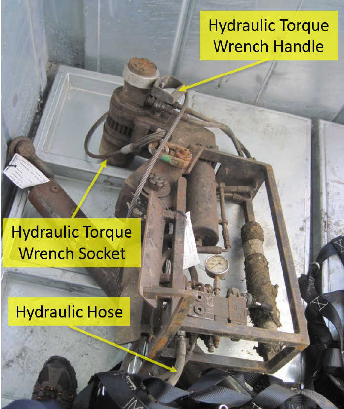
14
overhead winch (see “Hydraulic Utility Winch” section for further details) that assists in hanging
the HTW at an adequate height for either adding or removing the riser bolts.
Figure 8 – Hydraulic Torque Wrench
The Panel requested, compiled, and reviewed the following documentation pertinent to
understanding the HTW’s operational abilities and its impacts on the incident:
• Examination of a Hydraulic Torque Tool Socket Failure - Stress Engineering Services, Inc.
(“Stress Engineering”)
• Pulling BOP on Marine Riser - Pacific BOP 6
th
Generation
• HR-40/33C Riser Tool Operation & Maintenance - Power Tork Hydraulics, Inc.
The “Examination of a Hydraulic Tool Socket Failure” report analyzed the mechanical integrity
of the HTW, more specifically the cause of the crack on its socket, through various engineering
assessments. Stress Engineering examined the socket piece and associated bolts to determine if
any indication of long-term wear was present. Stress Engineering also compared deformation

15
potential with a newly manufactured like-in-kind socket. The Stress Engineering report
concluded that the equipment failed due to extensive tensile stress acting on the socket at the
time of the incident, which resulted in the fissure extending across the socket (Figure 9).
Figure 9 – Fissure Across Hydraulic Torque Wrench Socket after the Incident
The “Pulling BOP on Marine Riser” procedure described the numerous tasks for each rig
department to successfully complete the riser pull operation. Before detailing the job steps, the
document labels the positions, equipment, and administrative safeguards necessary to begin the
work. Some of the activities described in the procedure to be completed in preparation for
pulling the riser included picking up the landing joint, closing the slip joint, and unlatching the
subsea BOP. Although the procedure is a beneficial framework for completing the operation, it
does not expand on how and when to use the HTW.
The “HR-40/33C Riser Tool Operation & Maintenance” manual for the HTW used at the time of
the incident details all HTW components and their associated assembly and disassembly to
ensure proper operation. Some examples of the HTW component operations include the hoist
ring installation, drive pawl lift bolt adjustment, and hose connection for supplying hydraulic
pressure. Additionally, the manual provides a table with corresponding pressure settings required
for achieving the desired torque. Furthermore, this manual is available for use by company
representatives as a guide to assist with troubleshooting any malfunctions encountered by the
HTW.
Based on the evidence gathered from various interviews, all relevant personnel involved in the
riser pull operation had ample experience conducting this job on multiple occasions prior to the
incident. The RFC routinely rotated between roles of HTW Operator, HTW Assistant, and HUW
Operator. The RFC inspected all equipment and confirmed adequate pressure before starting the
job. The RFC responded unequivocally that they never had witnessed an incident such as this
involving the HTW.

16
HYDRAULIC UTILITY WINCH
The HUW is the key supplemental equipment involved in the incident. As mentioned in the
HTW section previously, the HUW connects the HTW support cable through a spring-loaded
balancer known as the zero-gravity compensator to support the significant weight of the HTW on
the rig floor. The HUW assembly is shown in Figure 10. The HUW was the actual mechanism
used for vertically hoisting the HTW to the proper operational height via the use of the HUW
electronic remote controller.
Figure 10 – Winch Assembly
The Panel primarily reviewed the Pacific Maintenance Records for the HUW and its associated
components to understand its operational abilities as well as to understand its impacts on the
incident. The maintenance logs indicate that certain HUW parts are required to be inspected at
established intervals to identify any deficiencies with the equipment. The results from the 1-year
and 5-year inspection intervals were provided to the Panel by TEPUSA. The Panel noted that the
inspection included an evaluation of the overall condition of the HUW, along with verification
that parts such as the wire rope, drum, filters, valves, fittings, etc., did not exhibit any fatigue,
wear, or damage. The Panel noted that neither inspection identified deficiencies associated with
the HUW. Therefore, no corrective maintenance work orders were required to be initiated.
Based on the evidence gathered from various interviews, all relevant personnel involved in the
riser pull operation had ample experience conducting this job on multiple occasions prior to the
incident. The RFC routinely rotated between roles of HTW Operator, HTW Assistant, and HUW
Operator. Despite the RFC’s familiarity with the equipment and operation, the interviewees’
responses regarding when to utilize the HUW were inconsistent and that the HUW is not
intended to be utilized beyond setting the initial height of the HTW.
17
SAFETY AND ENVIRONMENTAL MANAGEMENT SYSTEM FACTORS
JOB SAFETY ANALYSIS/TASK RISK ASSESSMENT
Pursuant to 30 CFR 250.1902(b), a Job Safety Analysis (JSA) must be completed for all OCS
activities identified or discussed in an operator’s SEMS program. The purpose of the JSA is to
identify all potential hazards and their associated mitigation measures for particular tasks and to
verify that they are understood by the crew conducting the job. As companies’ management
system programs have matured since the inception of the SEMS Final Rule in 2010, the use of
JSAs has become standard practice for all lessees and operators throughout the GOM to help
ensure that operations are conducted in a safe manner. Pacific’s internal terminology reflects that
a JSA is known as a “Task Risk Assessment” (TRA).
Pacific’s TRA form consists of many factors to be recognized by the personnel involved in an
operation. It contains the task step descriptions in sequential order, as well as the risk
descriptions, overall risk scores, and risk reduction measures associated with each itemized task
description. For large-scale operations, Holding Points are included in the TRA. Holding Points
can be defined as pre-determined pauses before initiating critical tasks in order to conduct
additional hazard assessments with the job crew. Once the TRA is reviewed, it is signed by each
crew member involved in the job to confirm their acknowledgment. Furthermore, there is a
supporting document that Pacific bundled with the TRA called the “Written Work Planning
Form” (WWPF). The WWPF covers additional considerations pertinent to the TRA, such as
steps to review associated work instructions, permits, and emergency response procedures. It
also contains human factor elements, such as checks to verify adequate individual training and
competency and checks for anyone experiencing fatigue or impairment.
The two TRAs used to conduct the riser pull operation leading up to the incident were
“Operating Utility Hoist (Hydraulic Winches)” and “Pulling BOPs on Marine Riser (Includes
Stack Hopping).” The former TRA refers to the person assigned to operate the HUW to assist in
setting the height of the HTWs. The latter TRA refers to the team members, both in the subsea
department and on the rig floor, assigned to hoist and secure the riser pipe on the Khamsin to
begin separation. Each TRA and associated WWPFs were reviewed and signed by all personnel
involved in the riser pull operation during the pre-tour meeting on August 23, 2020, at 0000
hours.
The Panel identified many gaps associated with the TRAs and the WWPFs. For example, the
TRAs did not address the potential hazard of the HTW getting stuck on the beveled edge of the
TJ and turning the HTW into a projectile by using the HUW to assist in freeing the HTW.
Additionally, the RFC did not formally convene during the Holding Point before the use of the
HTWs. Moreover, the WWPFs contained a feedback section to gauge if anyone had performed
the operations before, and it encouraged sharing of prior experiences (Figure 11). During
interviews of personnel involved in the incident, the Panel was informed that prior experience
with the HTW becoming stuck on riser bolts was not shared amongst the RFC, nor was prior
experience with using the HUW to help free a stuck HTW shared. The WWPF in Figure 11
below only notes that the RFC has completed the job before, rather than elaborating on prior
experiences and associated hazards previously encountered. Each of the aforementioned
deficiencies has been classified as a probable cause linked to the incident occurrence, and they

18
are detailed further in the “Conclusions” section of this report.
Figure 11 – Excerpt from Written Work Planning Form to Pull LMRP/Riser on the Date of the Incident
STOP WORK AUTHORITY/STOP WORK OBLIGATION
Stop Work Authority (SWA) was determined by the Panel to be a crucial factor leading up to the
incident. Pursuant to 30 CFR 250.1930(a), SWA “procedures must grant all personnel the
responsibility and authority, without fear of reprisal, to stop work or decline to perform an
assigned task when an imminent risk or danger exists.” Pacific’s internal terminology that
mirrors SWA is known as Stop Work Obligation (SWO). According to the Pacific SWO training
curriculum, SWO is defined as:
The responsibility and duty of an individual to stop any work, provided it is safe to do so,
that he or she thinks might pose an unacceptable risk or cause concern. According to the
obligation, which was signed by Pacific’s management, personnel are expected to stop
any activity under this obligation, including those performed by coworkers, client
representatives, contractors, management, et cetera.
The Panel reviewed applicable policies regarding the proper occasions to formally initiate the
various SWO levels, studied the Khamsin’s SWO event history, and assessed personnel’s
understanding of SWO. To assess personnel understanding of the official SWO definition, the
Panel explored the topic during personnel interviews, in which multiple RFC members expressed
that SWO is always encouraged and can be initiated without any repercussions.
The SWO standard covered a multitude of topics, such as positional responsibilities, drills,
audits, and training. However, the most critical topic consisted of the application of SWO and
how to properly record and report the event to supervisors. To achieve this, Pacific distinguished
SWO Severity Levels in its SWO standard. Severity Levels 1 and 2 are considered minor, only
requiring an Observation/Feedback Card to be filled out to document the occurrence (Figure 12).
Severity Levels 3, 4, and 5 are considered major, requiring a UWA Report Form to be filled out
to document the occurrence (Figure 13). Multiple personnel stated during interviews that they
19
were unaware of the UWA Report Form and the different severity levels for SWO. Furthermore,
the UWA called SWO when he arrived at the incident scene, as shown by his signature on the
UWA Report Form that the Panel received. Since the UWA was not in close proximity to the
spider gimbal platform at the time of the incident, an RFC member should have called SWO due
to the complications that were encountered during the riser pull operation.
Additionally, the Panel found this incident to be the first instance aboard the Khamsin during its
time under contract with TEPUSA for which SWO was initiated with an associated UWA Report
Form. As summarized in the Pre-Incident History section, an injury occurred on July 29, 2020,
during crane operations in which the opportunity to initiate SWO presented itself but never was
utilized. The Khamsin was under contract with TEPUSA at that time.

20
Figure 12 – Observation/Feedback Card

21
Figure 13 – Ultimate Work Authority Report Form Template
Finally, personnel involved in the operation leading up to the incident stated during interviews
that using the HUW to help free an HTW stuck on the tapered section of the TJ was not standard
procedure nor part of the TRA. Even though this was known by some of the RFC, SWO was not
applied to reassess the job before the incident occurred, nor was this hazard ever identified
through the Observation/Feedback Card program.
TRAINING
BSEE regulations at 30 CFR 250.1915 require the establishment and implementation of a
training program so that all personnel are trained in accordance with their duties and
responsibilities to work safely. Pacific states in its Training and Development Policy that it is a
direct line management responsibility to ensure that personnel have the required and appropriate
training to perform their job duties. Some core training requirements that Pacific tracks for all
offshore personnel include Marine Debris, International Association of Drilling Contractors
RigPass/SafeGulf, Bloodborne Pathogens, and Global Code of Conduct. Other training
requirements pertinent to specific job duties and well operations aboard the Khamsin include
International Association of Drilling Contractors Well Control, Confined Space Entry, Energy
Isolation/Lockout-Tagout, Fall Protection, and Permit to Work. TEPUSA and Pacific verify
22
individual personnel training compliance through a monitoring system called ISNetworld. The
monitoring system vetting process includes assessing various training and competency
qualifications through a Review and Verification Services questionnaire. The questionnaire
module evaluates knowledge and skills via a scoring system through fit-for-purpose
questionnaires tailored to the particular offshore training requirement. Personnel’s Review and
Verification Services questionnaire and applicable certifications are stored in ISNetworld and are
readily accessible upon request for TEPUSA and Pacific to validate training compliance.
As an additional training verification measure beyond the ISNetworld’s Review and Verification
Services program, Pacific develops and makes available Equipment Familiarization Manuals
(EFMs) for personnel to review. An EFM is an operating procedure for a specific piece of
equipment that details major components, maintenance, technical data, and other critical items
pertinent to a tool. The EFMs are shared only with targeted positions that are explicitly assigned
to utilize the equipment to fulfill their positional responsibilities. An EFM was created in April
2017 for the safe and effective use of the HUW.The Panel discovered through its investigation
that the HTW did not have an associated EFM for its operation, despite being a complementary
piece of equipment to the HUW.
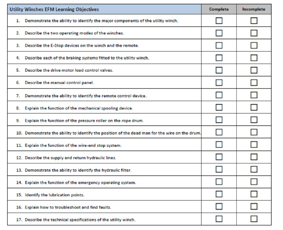
To reinforce the key takeaways from the EFMs, Pacific incorporated a supplemental Learning
items to ensure knowledge regarding how to properly function a specific tool. Furthermore, the
checklist includes hands-on demonstrations to be completed on the job site for the assessor to
gauge the level of knowledge the trainee had retained. While there was an EFM Learning
Objectives form dedicated to the HUW, as shown in Figure 14, the only member of the RFC to
possess documented evidence of completion was the Assistant Driller (i.e., the DFO). No other
RFC members had concrete evidence to substantiate the completion of the EFM Learning
Objectives for the HUW.
23
Figure 14 – Hydraulic Utility Winch Equipment Familiarization Management Learning Objectives
Despite the number of core and advanced training courses required to be completed by Khamsin
personnel, Pacific management never officially developed a formal training module for either the
HUW or the HTW as a foundational education for the equipment. Pacific has since generated
and rolled out fleet-wide, computer-based refresher training exercises for the HUW and the
HTW that must be completed annually by applicable operational personnel.
DRILL FLOOR OBSERVER
The DFO is a position created by Pacific as an additional safeguard for monitoring well
operations on the rig floor. Pacific established this position in October 2015 as a result of a
fatality that occurred on its Santa Ana drillship involving a malfunction of the pipe racking
system fingerboard latches. The DFO’s primary responsibility is to initiate SWO if an unsafe act,
condition, or practice is observed during work. A DFO is required to be onsite on the rig floor
during well operations that involve ancillary equipment in motion in the red zone. The red zone
boundaries can be defined as between the riser and pipe catwalks, inclusive of the rear and
forward side of the riser, the pipe setback area, and the main and auxiliary drawworks. The red
zone is an area of heightened risk for personnel due to dropped object potential, pressurized
systems, and other relevant hazards.

24
To be eligible for a DFO position, personnel must complete the Short Service Employee
program, and have three months minimum experience on the rig floor and six months minimum
experience in a floorhand position or higher. Additionally, the final criterion is the successful
completion of the applicable training module. The Pacific DFO training course covers the proper
attire for identification, communication methods, red zone management, and other instructions
when in an active DFO role. Furthermore, to validate understanding of the DFO training course
objectives, a supplemental DFO checklist must be completed and signed off by a direct
supervisor. As previously mentioned, the Assistant Driller was designated as the DFO at the time
of the incident.
During the investigation, the Panel identified a significant flaw in the DFO position description.
For the riser pull operation, the DFO oversaw the preliminary work, such as unlocking and
laying out the diverter. The preliminary work required equipment to be moved throughout the
red zone. However, when the RFC set the TJ on the spider gimbal deck and began using the
HTWs and HUW, the DFO no longer was required due to rig floor equipment becoming static.
As a result, the rig floor was lacking this designated position to trigger SWO when the unsafe act
of pulling on the HUW commenced.
CONCLUSIONS
The Panel concluded that the incident occurred due to both “Probable Causes” and “Contributing
Causes.” The Panel followed the BSEE National Investigations Handbook’s definition of
“Probable Causes” as those actions, events, or conditions that:
• Would have prevented the incident event from occurring, if corrected;
• Contributed significantly to the incident; and
• Have the most compelling supporting evidence as to both existence of the cause and the
degree of its contribution to the incident.
The Panel followed the BSEE National Investigations Handbook’s definition of “Contributing
Causes” as those actions, events, or conditions that:
• May have prevented the incident event from occurring, if corrected;
• Contributed somewhat to the incident; and
• Have less compelling evidence than the probable causes.
PROBABLE CAUSES
1) Insufficient Hazard Recognition
a. Although per multiple interviews there was a collective understanding of the
limited bolt clearance due to the beveled edge design of the TJ, the RFC did not
identify the possibility of the HTW becoming hung up on this section of the riser.
The RFC did not recognize this restricted joint space to be hazardous and focused
primarily on mitigating the potential for the HTW socket becoming stuck on the
riser flange bolts.
b. Multiple personnel were unaware of the hazard and stored energy in the stuck
HTW if the HUW was employed as a remediation measure to free a stuck HTW.
25
2) Lack of Comprehensive Understanding of the Task Risk Assessment
a. The correct interpretation of the TRA for the riser pull operations is to use the
HUW only to set the initial height of the HTW(s). However, this task step was not
understood by the RFC as evidenced by rig personnel utilizing the HUW as an
option to unbind the HTW at the time of the incident.
b. A Holding Point to discuss the job did not occur immediately before the RFC
began to utilize the HTW to unscrew the riser bolts. Review and discussion of the
TRA only occurred at the beginning of the shift, not at the required Holding Point
as indicated on the TRA. Due to difficulties encountered with the MUX Subsea
Drilling Controls Line at the beginning of the shift, the riser pull did not occur
until hours later when the MUX Subsea Drilling Controls Line issues were
resolved. Thus, the required Holding Point before laying out the TJ did not take
place.
3) Failure to Effectively Communicate Learnings from Previous Riser Pull Operations
a. Although evidence was provided to the Panel that indicated findings from
previous riser pull jobs were shared amongst the RFC via the
Observation/Feedback Card program, the appropriate time to utilize the HUW
was never discussed. Therefore, the HUW being applied as a corrective action to
free the stuck HTW was never agreed upon by the RFC as an acceptable practice.
b. Although evidence was provided to the Panel that indicated findings from the
previous riser pull jobs were shared amongst the RFC via the
Observation/Feedback Card program, the stuck-HTW potential was never
discussed. Therefore, associated mitigation methods for the stuck-HTW potential
were never discussed.
4) Lack of Training
a. No formalized training module and/or competency program was implemented to
ensure the safe operation of the HTW and the HUW.
5) Adverse Design of the Khamsin Hydraulic Torque Wrenches and Hydraulic Utility Winch
a. The configuration of the Power Tork HR-40/33C HTW is not fully compatible
with the tapered edge design of the NOV Shaffer 21-inch outer diameter 90-feet
Class H riser’s FT-H TJ, as evidenced by the HTW getting stuck when in
operation.
b. The HUW and its associated components (e.g., the zero-gravity compensator)
lacked a load indication feature for monitoring the amount of force being applied
to the HTW.
6) Failure to Consider Alternative Remediation Method for the Stuck Hydraulic Torque Wrench
a. The HTW includes the capability to torque in a downward motion. The process
requires the Operator to manually swap the hydraulic hoses to apply pressure in
the opposite direction. Despite this remediation option being available at the time
of the incident, it was never explored.
C
ONTRIBUTING CAUSES
1) Failure to Initiate Stop Work Obligation

26
a. Although a member of the RFC acknowledged to the Panel the danger of using
the HUW while floorhands were on the spider gimbal deck, SWO was not
executed to discuss this hazard before the incident occurred.
b. Due to some of the RFC being unaware of the hazards associated with the riser
pull operation, SWO was not considered applicable by some of the RFC at the
time of the incident.
c. Based on multiple interviews conducted by the Panel, there was a lack of
understanding of the various tiers of SWO, as well as how to properly implement
the UWA Report Form, despite SWO training consisting of a global requirement
to be completed as part of the rig onboarding process. The UWA was the
individual who officially initiated SWO despite not being in close proximity to
the spider gimbal platform at the time of the incident. A member of the RFC at
the time of the incident should have initiated SWO.
d. Pacific (while under contract with TEPUSA) failed to initiate SWO for an injury
that occurred on July 29, 2020. The August 23, 2020 fatality was the first
documented instance that SWO was formally initiated aboard the drillship during
its time under contract with TEPUSA. The UWA was the individual who
officially initiated SWO despite not being in close proximity to the spider gimbal
platform at the time of the incident. A member of the RFC at the time of the
incident should have initiated SWO. The aforementioned examples exemplify the
potential reluctance to trigger SWO at the appropriate occasion.
e. The official role of the DFO does not include monitoring auxiliary equipment
once movement ceases in the red zone. As a result, the DFO responsibilities did
not encompass the oversight of the riser joint breakout task. Therefore, the DFO
did not have the opportunity to initiate SWO.
RECOMMENDATIONS
The conclusions developed by the Panel yield associated recommendations aimed at improving
safety performance and preventing a recurrence or similar event sequence on the OCS. The
recommendations have been classified by the Panel as either “SEMS-related” or “Job-specific.”
“SEMS-related” recommendations can be defined as holistic suggestions for operators to
implement on a management system scale beyond the rig level. “Job-specific” recommendations
can be defined as suggestions that directly pertain to the riser pull operation. The Panel believes
that both “SEMS-related” and “Job-specific” recommendations should be performed to further
promote and protect the health and safety of personnel.
27
SEMS-RELATED RECOMMENDATIONS
The Panel recommends that lessees and operators working on the OCS review the processes in
place that address:
1) Hazard Recognition and Job Safety Analysis
a. Conduct comprehensive assessments of all portions of an offshore operation to
ensure all potential hazards along with associated mitigation measures have been
identified.
b. Verify all JSA steps are acknowledged and agreed upon by the entirety of the
crew involved in the task.
2) Communication
a. Institute or continue promoting a program for sharing on-the-job learnings (e.g.,
observation cards) to identify improvements for conducting operations in a safe
manner.
3) Training and Competency
a. Incorporate job-specific knowledge and skills modules into the SEMS Training
Element to ensure personnel understand how to properly conduct both high-risk
and routine tasks that pertain to their areas of expertise.
4) Stop Work Obligation
a. Reinforce to personnel that they have the power to initiate SWO if at any point a
deviation occurs from the originally established JSA.
b. Document all SWO events to ensure the proper supervisory approval is granted
before resuming work.
c. Incorporate a process for trending unsafe observations and imminent dangers
resulting in SWO being initiated to assist in identifying potential improvement
opportunities.
JOB-SPECIFIC RECOMMENDATIONS
The Panel recommends that lessees and operators working on the OCS consider the processes in
place that address:
1) Task-level Hazard Analysis
a. Ensure the task-level hazard analysis (i.e., JSA, TRA, or other applicable
document pertaining to the hazard review required for the task) associated with
the riser pull operation captures that the HUW is only to be utilized as an
alignment tool for setting the HTW height before breaking out bolts.
i. Ensure the JSA associated with the riser pull operation emphasizes
that the HUW is never to be used as a method to rectify a stuck
HTW.
b. Ensure that pre-job reviews of the task-level hazard analysis promote the sharing
of feedback from previous experiences, such as the proper action to take when the
HTW becomes stuck on riser bolts.
2) Training and Competency
28
a. Require HUW Operating Procedures/Manuals to be reviewed and acknowledged
by positions involved in the riser pull operation as a pre-requisite/pre-qualification
before beginning work aboard the rig.
b. Conduct thorough on-the-job training and competency assessments to ensure all
employees involved in the riser pull operation fully recognize the hazards
associated with this job.
3) Stop Work Obligation
a. Stress to personnel the importance of using SWO during the riser pull operation if
the HTW socket gets stuck.
b. Seek guidance from supervisory personnel to assess the situation to ensure the
hazard can be eliminated/mitigated effectively before recommencing work.
4) Drill Floor Observer Responsibilities
a. When a DFO or similar position is to be incorporated during operations on the rig
floor, expand the formal DFO role to include monitoring all aspects of any job in
the designated red zone on the rig floor (including when ancillary equipment is
not in motion).
5) Torque Wrench and Hydraulic Winch Designs
a. Consider acquiring and utilizing an HTW that consists of a more favorable
design, size, and capability to allow for the safe disengagement of the TJ.
b. Explore options for employing a load indicator, or a similar mechanism that
achieves the same goal, onto the HUW package.
