
Refer to the service manual in the GSPN(see the rear cover) for the more information.
AIR CONDITIONER CONTENTS
SYSTEM AIR CONDITIONER
1. Precautions
2. Product Specifications
3. Disassembly and Reassembly
4. Troubleshooting
5. PCB Diagram
6. Wiring Diagram
7. Reference Sheet
AC012/018/024MNADCH
INDOOR UNIT OUTDOOR UNIT
Model :
AC012MNADCH/AA
AC018MNADCH/AA
AC024MNADCH/AA
AC030MNTDCH/AA
AC036MNTDCH/AA
AC012KXADCH/AA
AC018JXADCH/AA
AC024JXADCH/AA
AC030JXADCH/AA
AC036JXADCH/AA
AC012KXADCH
AC024JXADCH
AC030JXADCH
AC018JXADCH
AC036JXADCH
AC030/036MNTDCH

2 Samsung Electronics
Contents
11. Precautions
........................................................................................................................................
1-1
1-1 Precautions for the Service
..............................................................................................................
1-1
1-2 Precautions related to static electricity and PL
............................................................................
1-1
1-3 Precautions related to product safety
...........................................................................................
1-2
1-4 Other precautions
..............................................................................................................................
1-2
12. Product Specifications
...............................................................................................................
2-1
2-1 The Feature of Product
.....................................................................................................................
2-1
2-2 Product Specifications
......................................................................................................................
2-2
2-3 Accessories
..........................................................................................................................................
2-5
13. Disassembly and Reassembly
...............................................................................................
3-1
3-1 Indoor Unit
.........................................................................................................................................
3-2
3-2 Outdoor Unit
.....................................................................................................................................
3-18
14. Troubleshooting
............................................................................................................................
4-1
4-1 Troubleshooting for indoor unit
..................................................................................................
4-1
4-2 Troubleshooting for outdoor unit
.................................................................................................
4-11
4-3 Troubleshooting by symptoms
.....................................................................................................
4-13
4-3-1 Indoor temperature sensor (open/short)
..........................................................................
4-13
4-3-2 Indoor heat exchanger temperature sensor (open/short)
.............................................
4-14
4-3-3 Indoor FAN error
.....................................................................................................................
4-15
4-3-4 Communication error after finishing Tracking
.................................................................
4-16
4-3-5 Indoor unit float sensor error
...............................................................................................
4-17
4-3-6 EEPROM circuit failure
...........................................................................................................
4-18
4-3-7 Outdoor unit is not powered on
.........................................................................................
4-19
4-4 Troubleshooting by symptoms
................................................................................................................... 4-21
4-4-1 Communication error
..........................................................................................................
4-21
4-4-2 Outdoor temperature sensor error
....................................................................................
4-22
4-4-3 Outdoor Coil temperature sensor error
............................................................................
4-24
4-4-4 Outdoor Discharge temperature sensor error
.................................................................
4-26
4-4-5 Outdoor Discharge over temperature error
.....................................................................
4-28
4-4-6 Outdoor Fan motor error
.................................................................................................................... 4-29
4-4-7 Compressor starting error .................................................................................................................. 4-30
4-4-8 Compressor wire missing error/rotation error .......................................................................... 4-31
4-4-9 O.C(Over Current) error ....................................................................................................................... 4-32
4-4-10 DC_link voltage sensor error .......................................................................................................... 4-33
4-4-11 DC_link voltage under/over error, Over voltage protection error/PFC over load ..... 4-34

Samsung Electronics 3
4-4-12 DC_link voltage sensor error ........................................................................................................... 4-35
4-4-13 Current sensor error/Input current sensor error .................................................................... 4-36
4-4-14 Heatsink sensor error/Heatsink over heat ................................................................................. 4-37
4-4-15 Comp Vlimit error/Comp current limit error ............................................................................ 4-38
4-4-16 EEPROM error/OTP error .................................................................................................................. 4-39
4-4-17 AC zero cross signal error ................................................................................................................. 4-40
4-4-18 Operation condition secession error............................................................................................ 4-41
4-4-19 Capacity miss match error ............................................................................................................... 4-42
4-4-20 Gas leak error ........................................................................................................................................ 4-43
15. PCB Diagram
.....................................................................................................................................
5-1
5-1 Indoor Unit
.........................................................................................................................................
5-1
5-2 Outdoor Unit
.....................................................................................................................................
5-4
16. Wiring Diagram
..............................................................................................................................
6-1
6-1 Indoor Unit
........................................................................................................................................
6-1
6-2 Outdoor Unit
....................................................................................................................................
6-2
7. Reference Sheet
.............................................................................................................................
7-1
7-1 Index for Model Name
......................................................................................................................
7-1
7-2 Refrigerating Cycle Diagram
............................................................................................................
7-2

Samsung Electronics 1-1
1. Precautions
1-1 Precautions for the Service
XUse the standard parts when replacing the electric parts.
– Confirm the model name, rated voltage, rated current of the electric parts.
XWhen repairing the equipment, connection of the harness parts must be firm and solid.
– A loose connection may cause noise or other malfunction.
XWhen assembling and disassembling the equipment while it is laid down, lay it on soft cloth.
– Otherwise it may scratch the back of the exterior of the product.
XRemove dust or dirt completely from the housing block, wiring block and service parts during repair.
– This helps prevent the danger of fire caused by tracking or short circuit.
XFasten the valve caps of service valves and charging valves of outdoor unit as much as possible using adjustable wrenches.
XCheck the status of the components’ assembly after repair service.
– The status must be the same as before the repair service.
1-2 Precautions related to static electricity and PL
X The PCB power supply block is susceptible to static electricity. Therefore, care must be taken during repair or measuring
while the power is on.
– Wear insulation gloves for PCB repair or measuring.
X Check whether the installation location is at least two meters away from other electronic products such as TV, video, or
audio.
– Otherwise, the video quality might be degraded or noise might be generated.
X Do not let end users repair the products themselves.
– Unauthorized disassembly might cause electric shock or fire.

1-2 Samsung Electronics
1-3 Precautions related to product safety
X Do not pull the power cord and do not touch the power plug or aux power switch with wet hands.
– It might cause electric shock or fire.
X A damaged power line or power plug must be replaced to prevent danger.
X Do not bend the power cable with excessive force, and do not place a heavy weight on the case as it might damage the
cable.
– It might cause electric shock or fire.
X Do not use multiple electric outlets.
– This might cause electric shock or fire.
X Connect the ground terminal when necessary.
– You must connect the ground terminal if you determine that there is a danger of electric leakage due to moisture or water.
X Unplug the power cable or turn off the auxiliary power switch for electric part replacement and repair service.
– Otherwise it might cause electric shock.
X Instruct end users to separate the batteries from the remote controllers and store them separately when the product is not
used for long time.
– Otherwise leakage from the dry cell may cause problems with the remote controller.
1-4 Other precautions
X The pipes should have no leaks during installation, and the compressor must be stopped before removing connecting
pipes for pump down work. Operating the compressor while the service valve is open and coolant pipe is not properly
connected may cause explosion or injury due to abnormal high pressure created inside the coolant cycle as the air can be
absorbed through the pipe.
X Pump Down work procedure (When uninstalling the product)
– Turn on the air conditioner, select cooling operation, and run the compressor for more than three minutes.
– Release the high pressure and low pressure valve caps.
– Close the high pressure valve completely using an L-wrench
– After about two minutes, close the low pressure valve completely.
– Stop running the air conditioner.
– Separate the connecting pipe.

Samsung Electronics 2-1
X Built-in Cassette Type
After installed, the air conditioner can be harmonized with a room interior.
X High Performance & Energy Saving
With the advanced BLDC inverter technology, it makes a room cool with highly energy saving and arises the efficiency of air conditioner.
XLong Ambient Operation(In Low Temperature)
It can arise the reliability and the capacity of the air conditioner, especially operated in low temperature.
X Eco-friendly Product(Lead-Free, ROHS, WEEE)
X Easy installation of ultra-lightweight indoor unit
2. Product Specifications
2-1 The Feature of Product

2-2 Samsung Electronics
ITEM
AC012MNADCH
AC012KXADCH
AC018MNADCH
AC018JXADCH
IMAGE
Indoor Unit
Outdoor Unit
Remote Controller
Power Product 1Φ, 220~240V, 50Hz 1Φ, 220~240V, 50Hz
Indoor L x H x D mm 750*246*249
896*261*261
Outdoor L x H x D mm 790*285*548 880*310*638
Indoor Product kg(Net) 7.6 10.6
Outdoor Product kg(Net) 36.2 45.0
Capacity
Cooling(STD) Btu/h 12 000
18 000
Heating(STD) Btu/h
14 000 20 000
Power
Consumption
Cooling(STD) W
1220 2160
Heating(STD) W
1680 1960
Operation
current
Cooling(STD) A
5.7 9.4
Heating(STD) A
7.4 8 .5
Noise
(Cooling/
Heating)
Indoor unit
In case of strongest air
blow
dBA
43/43 48/48
Outdoor unit
In case of strongest air
blow
dBA
54/54 58/58
Refrigerant (R410A) g 1050 1300
Connecting Pipe
Liquid mm 6.35
6.35
Gas mm
9.52 12.70
Additional Refrigerant (R410A) g/m
10 10
Standard m
7. 5 7. 5
Extension length(Total) m 20
30
Extension length(Elevation) m
15 15
Option Code
Product
Option
0100FC-19548C-272328-371708
0100FC-19548E-27343E-3C170D
Installation
Option
020000-100000-200000-300000
020000-100000-200000-300000
2-2 Product Specifications

Samsung Electronics 2-3
ITEM
AC024MNADCH
AC024JXADCH
AC030MNTDCH
AC030JXADCH
IMAGE
Indoor Unit
Outdoor Unit
Remote Controller
Power Product 1Φ, 220~240V, 50Hz 1Φ, 220~240V, 50Hz
Indoor L x H x D mm
1065*294*301 1280*345*253
Outdoor L x H x D mm 940*330*998 940*330*998
Indoor Product kg(Net) 14.5 18.5
Outdoor Product kg(Net) 64.5 70.0
Capacity
Cooling(STD) Btu/h 24 000
30 000
Heating(STD) Btu/h
27 000 32 000
Power
Consumption
Cooling(STD) W
2350 3150
Heating(STD) W
2560 3360
Operation
current
Cooling(STD) A
10.4 13.7
Heating(STD) A
11. 4 14 .7
Noise
(Cooling/
Heating)
Indoor unit
In case of strongest air
blow
dBA
51/51 55/55
Outdoor unit
In case of strongest air
blow
dBA
60/60 60/60
Refrigerant (R410A) g 2100 2600
Connecting Pipe
Liquid mm 6.35
9.52
Gas mm
15.88 15.88
Additional Refrigerant (R410A) g/m
10 22
Standard m
7. 5 7. 5
Extension length(Total) m 50
50
Extension length(Elevation) m
30 30
Option Code
Product
Option
0100FC-19547F-274750-37170D
0110FC-193573-275A64-37770D
Installation
Option
020000-100000-200000-300000
020000-100000-200100-300000

2-4 Samsung Electronics
ITEM
AC036MNTDCH
AC036JXADCH
IMAGE
Indoor Unit
Outdoor Unit
Remote Controller
Power Product 1Φ, 220~240V, 50Hz
Indoor L x H x D mm
1280*345*253
Outdoor L x H x D mm 940*330*1210
Indoor Product kg(Net) 18.5
Outdoor Product kg(Net) 88.0
Capacity
Cooling(STD) Btu/h
36 000
Heating(STD) Btu/h
40 000
Power
Consumption
Cooling(STD) W
3870
Heating(STD) W
4120
Operation
current
Cooling(STD) A
16.5
Heating(STD) A
17.8
Noise
(Cooling/
Heating)
Indoor unit
In case of strongest air
blow
dBA
55/55
Outdoor unit
In case of strongest air
blow
dBA
60/60
Refrigerant (R410A) g 2800
Connecting Pipe
Liquid mm
9.52
Gas mm
15.88
Additional Refrigerant (R410A) g/m
33
Standard m
7. 5
Extension length(Total) m
75
Extension length(Elevation) m
30
Option Code
Product
Option
0110FC-194594-276470-39670D
Installation
Option
020000-100000-200100-300000

Samsung Electronics 2-5
Item Description Code No. Q’ty Remark
Remote Control
DB93-15882S
1
Essential Offer
(Indoor Unit)
Batteries for Remote Control
4301-000121
2
USER &
INSTALLATION
MANUAL DB68-07119A
1
Remote Control Holder
DB61-06087A
1
M4 x 16 Tapped Screws
6002-000234
2
Cap Screws
DB67-01404B
(AC012/018/024MNADCH)
3
CARD WARRNATY DB68-02596B
1
Drain Plug
DB67-20011A
1
Essential Offer
(Outdoor Unit)
Rubber Leg DB67-01533A 4
INSTALLATION MANUAL DB68-06488A 1
2-3 Accessories

Samsung Electronics 3-1
Item Remarks
+SCREW DRIVER
Adjustable Wrench
(8mm, 10mm, 13mm)
M6, M8 Hex Wrench
XNecessary Tools
3. Disassembly and Reassembly

3-2 Samsung Electronics
3-1 Indoor unit
XAC012MNADCH / AC018MNADCH / AC024MNADCH
No Parts
Procedure Remark
1 PANEL-FRONT 1) Stop the driving of air conditioner and shut off
main power supply.
2) Detach FILTER PRE from the PANEL FRONT.
3) Cover Panel is assembled on bottom of indoor
unit as shown in the figure.
Remove the Cap Screw as shown on the right
side and then remove the screw and separate
the Cover Panel.

Samsung Electronics 3-3
No Parts
Procedure Remark
4) Cover Panel is fixed to body by Hook in center area and
side area.
5) Separate the hook after pushing both end of Cover
Panel as shown in the figure.
(Watch out for the damage of the hook)
6) Raise front part upward obliquely as shown in the
figure and then remove the hooks.
Center area
Side area
Side area
HOOK
026/035
052/071

3-4 Samsung Electronics
No Parts
Procedure Remark
Caution:
Assembly of Cover Panel after service end.
-
Reassembly is in the reverse order of the
removal.
- Piping and drain hose must be careful not to
damage and Progress must be done with both
hands.
Hook (Side)
Hook (Center)
Screw
Cap Screw

Samsung Electronics 3-5
No Parts
Procedure Remark
7) To detach the PANEL-FRONT from the main
frame, unfasten 2 screws at the bottom.
(use + Screw Driver)
8) To detach the COVER-PANEL from the main
frame, loosen 4 HOOK Structures.
When separate the hook :
Use the (-) screw Driver.
(-)Screw Driver Insert the hook and then pull the
hook as shown on the right side.
(Watch out for the damage of the hook)

3-6 Samsung Electronics
No Parts
Procedure Remark
9) Remove the Panel Frame from the Main
Frame as shown on the right side.

Samsung Electronics 3-7
No Parts
Procedure Remark
2
CONTORL IN
1) Lossen Sub PBA Wire.
Caution:
When you separate the connector,
pull pressing the locking button.
2) Lossen Stepping Motor, EEV, Display,
Sensor, SPI, Fuse Wire.
Caution:
When you separate the connector,
pull pressing the locking button.
3) Lossen Motor, Terminal Wire.
Caution:
When you separate the connector,
pull pressing the locking button.
4) Loosen Earth Wire.

3-8 Samsung Electronics
No Parts
Procedure Remark
5 EVAPORATOR 9) Take off the CASE-CONTROL from
the main frame after loosen the remaining
connector.
Caution:
When you separate the connector,
pull pressing the locking button.
3 TRAY DRAIN 1) To detach TRAY-DRAIN from the main frame,
pull the bottom of the TRAY-DRAIN towards
you.

Samsung Electronics 3-9
No Parts
Procedure Remark
4 Evaporator 1) Detach the HOLDER PIPE.
2) Unfasten the screw at the left side.
(use + Screw Driver)
3) Unfasten the screw at the right side.
(use + Screw Driver)
4) To detach Evaporator from the main frame,
pull the bottom of the Evaporator towards
you.

3-10 Samsung Electronics
No Parts
Procedure Remark
5 FAN MOTOR
&
CROSS FAN
1) Unfasten the screw. (use + Screw Driver)
2) Detach the FAN Motor case.
3) Unfasten the screw a little.
(use + Screw Driver)
4) Pull the CROSS-FAN to the left side.

Samsung Electronics 3-11
XAC030MNTDCH / AC036MNTDCH
No Parts
Procedure Remark
1 PANEL-FRONT 1) Stop the driving of air conditioner and shut off
main power supply.
2) Open the FRONT-GRILLE and pull out from the
PANEL-FRONT.
3) Detach COVER-TERMINAL from the PANEL
FRONT. (use + Screw Driver)
4) Loosen connector wire(white) and detach the
temperature sensor wire .
5) To detach the FRONT-PANELthe main frame,
unfasten 2 screw at the bottom.(use + Screw
Driver )
6) Take off the FRONT-PANEL,lifting up the bottom

3-12 Samsung Electronics
No Parts
Procedure Remark
2
TRAY DRAIN
1) Loosen stepping motor wire and detach the
hook of main frame.
2) To detach TRAY-DRAIN from the main frame, pull
the bottom of the TRAY-DRAIN towards you.
3) To detach TRAY-DRAIN from the main frame ,
pull the bottom of the TRAY-DRAIN towards you.
3
CONTROL IN
1) Unfasten the earth screw.(use + ScrewDriver)
2) Detach the temperature sensor and Humidity
sensor.
3) Detach the temperature sensor.

Samsung Electronics 3-13
No Parts
Procedure Remark
4) Loosen MOTOR wires(white).
5) Take off the CASE-CONTROL from the main
frame. (use + Screw Driver)
4 PBA 1) Loosen the STEP UP/DOWN connector(CN802).
Caution:
When you separate the connector,
pull pressing the locking button.
2) Loosen the FUSE CHK connector (CN140).
Caution:
When you separate the connector,
pull pressing the locking button.

3-14 Samsung Electronics
No Parts
Procedure Remark
3) Loosen the EVA IN/OUT connector. (CN403)
Caution:
When you separate the connector,
pull pressing the locking button.
4) Loosen the Humidity sensor connector(CN401).
->Option connector.
Caution:
The terminal is locking type.
So, when you separate terminals, pull pressing
the button.
5) Loosen the DISPLAY connector. (CN501).
Caution:
The terminal is locking type.
So, when you separate terminals, pull pressing
the button.
6) Loosen the POWER connector.
Caution:
When you separate the connector,
pull pressing the locking button.
Samsung Electronics 3-15
No Parts
Procedure Remark
7) Loosen the COMM wire connector(CN303).
Caution:
When you take off the PBA, don’t touch
the components.
Please hold the PBA both side.
8) Loosen the Motor connector(CN701).
Caution:
When you separate the connector,
pull pressing the locking button.
9) Take off the main PBA from the ASS’Y Control in.
Caution:
When you take off the PBA, don’t touch
the components.
Please hold the PBA both side.
5 EVAPORATOR 1) Unfasten the screw at the right side. (use +
ScrewDriver)

3-16 Samsung Electronics
No Parts
Procedure Remark
2) Unfasten the screw at the left side. (use +
ScrewDriver)
3) Detach the HOLDER PIPE. (use + Screw Driver)
4) Detach the BRACKET-EVAP. (use + Screw Driver)
5) Detach the HOLDER EVAP. (use + Screw Driver)
6) Loosen 1 fixing earth screw right side. (use +
Screw Driver)

Samsung Electronics 3-17
No Parts
Procedure Remark
6 FAN MOTOR
&
CROSS FAN
1) Loosen 6 fixing screws of HOLDER-MOTOR
2) unfasten the screw a little. (use + Screw Driver)
3) unfasten the screw a little and pull the MOTOR
FAN to the right side. (use + Screw Driver)
4) Loosen 1 fixing screws of HOLDER-FAN.(use +
Screw Driver)
5) unfasten the screw a little.(use + Screw Driver)
3-18 Samsung Electronics
■ AC012KXADCH
No Parts Procedure Remark
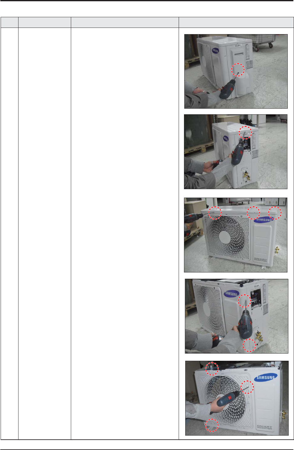
1 common work 1) loosen 1 pcs screw of cover control,and
detach it.
2) loosen 5 pcs screws on both right and
left cabniet side edges and to detach the
cover-top
3) Loosen 7 screwsfixed to disassemble
cabi-front , and detach it.
3-2 Outdoor Unit

Samsung Electronics 3-19
No Parts Procedure Remark
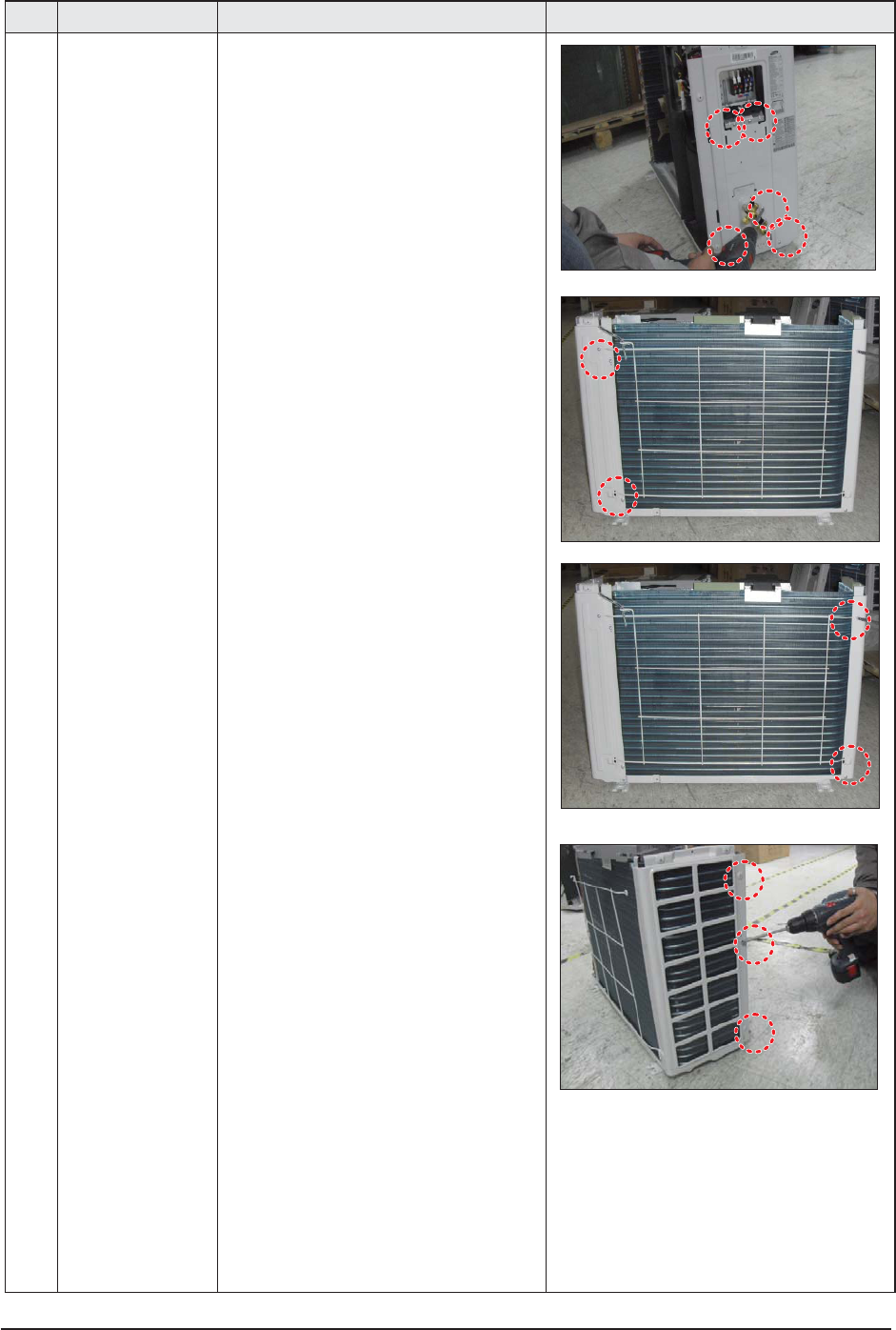
common work 4) loosen 7 screws to disassemble the cabi-
right ,and detach it.
5) loosen 2 screws to disassemble steel-bar.
6) loosen 3 screws to disassemble cabi-left.

3-20 Samsung Electronics
No Parts Procedure Remark
2 fan&motor 1) loosen 1 screw as indication and detached
the fan.
2) loosen 4 pcs motor screws and disconnect
the wire betwwen assy control out and motor.
3) loosen 2 pcs bracket-motor screw and
detach it.

Samsung Electronics 3-21
No Parts Procedure Remark
3 assy control out 1) lossen fixing 1 screw from cover -control
2) detach several connections from assy con-
trol out, take out assy control out.
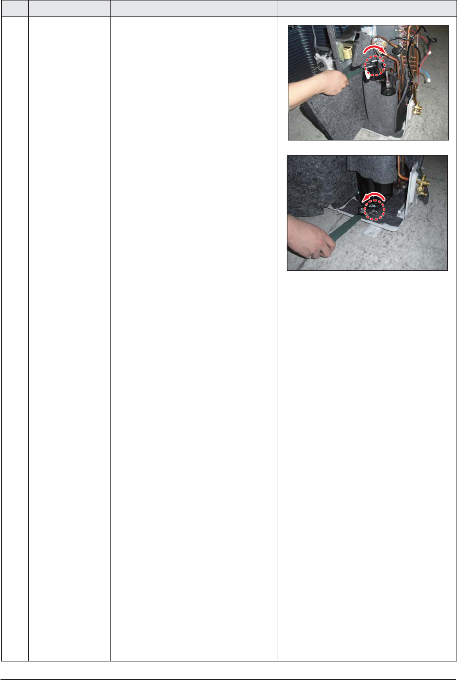
4 Heat exchanger 1) Release the refrigerant at first
2) Looosen fixing screw on both side.
3) Disaessembly the pipes in both inlet and
outlet with welding torch.
4) detach the heat exchanger.

3-22 Samsung Electronics
No Parts Procedure Remark
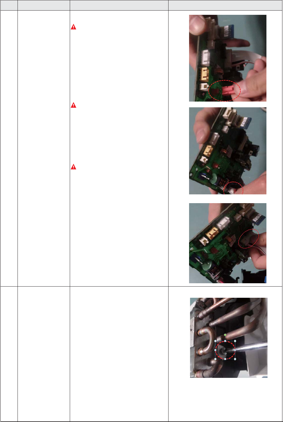
5 compressor 1) Disconnect the compressor lead wire .
2) Disassembly the felt comp sound.
loosen the 3 bolts at the bottom of

Samsung Electronics 3-23
No Parts Procedure Remark
1common work 1) loosen 1 pcs screw of cover control,and
detach it.
2) loosen 5 pcs screws on both right and
left cabniet side edges and to detach the
cover-top
3) Loosen 7 screwsfixed to disassemble
cabi-front , and detach it.
QAC018JXADCH
3-24 Samsung Electronics
No Parts Procedure Remark
common work 4) loosen 7 screws to disassemble the cabi-
right ,and detach it.
5) loosen 2 screws to disassemble steel-bar.
6) loosen 3 screws to disassemble cabi-left.

Samsung Electronics 3-25
No Parts Procedure Remark
2 fan&motor 1) loosen 1 screw as indication and detached
the fan.
2) loosen 4 pcs motor screws and disconnect
the wire betwwen assy control out and motor.
3) loosen 2 pcs bracket-motor screw and
detach it.

3-26 Samsung Electronics
No Parts Procedure Remark
3 assy control out 1) lossen fixing 1 screw from cover -control
2) detach several connections from assy con-
trol out, take out assy control out.
4 Heat exchanger 1) Release the refrigerant at first
2) Looosen fixing screw on both side.
3) disaessembly the pipes in both inlet and
outlet with welding torch.
4) detach the heat exchanger.
Samsung Electronics 3-27
No Parts Procedure Remark
5compressor 1) disconnect the compressor lead wire .
2)disassembly the felt comp sound.
loosen the 3 bolts at the bottom of

3-28 Samsung Electronics
No Parts Procedure Remark
1 Cabi Front RH
You must turn off the Power before
disassembly.
1) Unscrew and remove two mounting screw
in the Cabinet Front RH. (Use +Screw Driver)
2 Cabi Top 1) Unscrew and remove 9 screws
on each side of the Cabinet-Top.
(Use +Screw Driver)
3 Cabi Install Front 1) Unscrew and remove 1 screw
in the Cabinet-Install Front.
(Use +Screw Driver)
QAC024JXADCH, AC030JXADCH

Samsung Electronics 3-29
No Parts Procedure Remark
4 Guard Cond 1) Pull the sensor from Guard Cond.
2) Unscrew and remove 4 screws
in the Guard Cond.
(Use +Screw Driver)
5 Cabi Back RH 1) Pull the sensor from Cabi Back RH.
2) Unscrew and remove 4 screws
on each side of the Cabinet Back RH.
(Use +Screw Driver)

3-30 Samsung Electronics
No Parts Procedure Remark
6 Cabi Install Back 1) Unscrew and remove 1 screw
in the Cabinet-Install Back.
(Use +Screw Driver)
7 Cabi Front LF 1) Unscrew and remove 10 screws
in the Cabinet-Front LF.
(Use +Screw Driver)

Samsung Electronics 3-31
No Parts Procedure Remark
8 Fan 1) Turn 2 mounting nuts as shown in the
picture and remove it. (Use Adjustable
Wrench)

3-32 Samsung Electronics
No Parts Procedure Remark
9 Motor 1) Separate the Fan Propeller.
2) Unscrew and remove the 8 Motor mounting
screws. (Use +Screw Driver)
3) Disconnect the Motor wire From
Ass'y Control Out.
10 Bracket Motor 1) Unscrew and remove 2 mounting screws
in Bracket Motor. (Use +Screw Driver)

Samsung Electronics 3-33
No Parts Procedure Remark
11 Control Out 1) Disconnect 4 Connecters From
Ass'y Control Out.
2) Unscrew and remove 1 mounting screw
in Control Out. (Use +Screw Driver)
3) Separate Ass'y Control Out.

3-34 Samsung Electronics
No Parts Procedure Remark
12 Ass'y 4way Valve 1) Purge the Coolant first.
2) Unscrew and remove 2mounting screws
in muffler.
3) Unscrew and remove 2 mounting screws
in Service Valve. (Use +Screw Driver)
4) Separate the pipe from the Entrance/Exit
using a welder.
When removing the compressor,
Heat Exchanger, and Pipe, purge the
Coolant inside the Compressor
completely and remove the pipe
with a welding flame.

Samsung Electronics 3-35
No Parts Procedure Remark
13 Ass;y EEV Valve 1) Unscrew and remove 2 mounting screws
in Service Valve. (Use +Screw Driver)
2) Separate the pipe from the Entrance/Exit
using a welder.
14 Compressor 1) Unscrew and remove 1 mounting nut
in Cover Terminal. (Use Adjustable Wrench)
2) Separate the Compressor Felt Sound.

3-36 Samsung Electronics
No Parts Procedure Remark
3) As shown in the picture, unscrew and
remove 3 mounting screws from the
bottom. (Use Adjustable Wrench)
15 Cond Out 1) Unscrew and remove 3 screws
on each side of the Assy Cond Out.
(Use +Screw Driver)
2) Separate the Compressor Felt Sound.

Samsung Electronics 3-37
No Parts Procedure Remark
1 Cabi Front RH
You must turn off the Power before
disassembly.
1) Unscrew and remove two mounting
screw in the Cabinet Front RH.
(Use +Screw Driver)
2 Cabi Top
1) Unscrew and remove 9 screws
on each side of the Cabinet-Top.
(Use +Screw Driver)
3 Cabi Install Front
1) Unscrew and remove 1 screw
in the Cabinet-Install Front.
(Use +Screw Driver)
4 Guard Cond
1) Pull the sensor from Guard Cond.
2) Unscrew and remove 4 screws
in the Guard Cond.
(Use +Screw Driver)
QAC036JXADCH

3-38 Samsung Electronics
No Parts Procedure Remark
5 Cabi Back RH
1) Pull the sensor from Cabi Back RH.
2) Unscrew and remove 4 screws
on each side of the Cabinet Back RH.
(Use +Screw Driver)
6 Cabi Install Back
1) Unscrew and remove 1 screw
in the Cabinet-Install Back.
(Use +Screw Driver)
7 Cabi Front LF
1) Unscrew and remove 10 screws
in the Cabinet-Front LF.
(Use +Screw Driver)
8 Fan
1) Turn 2 mounting nuts as shown in
the picture and remove it.
(Use Adjustable Wrench)

Samsung Electronics 3-39
No Parts Procedure Remark
9 Motor
1) Separate the Fan Propeller.
2) Unscrew and remove the 8 Motor
mounting
screws. (Use +Screw Driver)
3) Disconnect the Motor wire From
Ass'y Control Out.
10 Bracket Motor
1) Unscrew and remove 2 mounting
screws in Bracket Motor.
(Use +Screw Driver)
11 Control Out
1) Disconnect 4 Connecters From
Ass'y Control Out.
2) Unscrew and remove 1 mounting
screw in Control Out.
(Use +Screw Driver)
3) Separate Ass'y Control Out.

3-40 Samsung Electronics
No Parts Procedure Remark
12 Assy 4way Valve
1) Purge the Coolant first.
2) Unscrew and remove 2 mounting
screws in Service Valve. (Use +Screw
Driver)
3) Separate the pipe from the
Entrance/Exit using a welder.
When removing the compres-
sor, Heat Exchanger, and Pipe,
purge the Coolant inside the
Compressor completely and
remove the pipe with a welding
flame.
13 Assy EEV Valve
1) Unscrew and remove 2 mounting
screws in Service Valve.
(Use +Screw Driver)
2) Separate the pipe from the Entrance/
Exit using a welder.

Samsung Electronics 4-1
4. Troubleshooting
You cannot set both of the indoor unit addresses and
the installation options in a batch: set both of them
respectively.
4-1-1 Common steps for setting the
addresses and options
MR-EC00 and MR-EH00 remote controls
Low Temp button
High Temp button
Mode button
Low Fan button
High Fan button
Setting the
option values
for setting the
options
NOTE
t The remote control display and buttons may vary
depending on the model.
1 Enter the mode for setting the options:
a Remove the batteries from the remote control, and
then insert them again.
b While holding down the
(High Temp) and
(Low Temp) buttons simultaneously, insert the
batteries into the remote control.
c Make sure that you are entered to the mode for
setting the options:
2 Set the option values.
CAUTION
t The total number of available options are 24: SEG1 to
SEG24.
t Because SEG1, SEG7, SEG13, and SEG19 are the page
options used by the previous remote control models,
the modes to set values for these options are skipped
automatically.
t Set a 2-digit value for each option pair in the following
order: SEG2 and SEG3 ¤ SEG4 and SEG5 ¤ SEG6 and
SEG8 ¤ SEG9 and SEG10 ¤ SEG11 and SEG12 ¤ SEG14
and SEG15 ¤SEG16 and SEG17 ¤ SEG18 and SEG20 ¤
SEG21 and SEG22 ¤ SEG23 and SEG24
SEG1 SEG2 SEG3 SEG4 SEG5 SEG6
0XXXXX
SEG7 SEG8 SEG9 SEG10 SEG11 SEG12
1XXXXX
SEG13 SEG14 SEG15 SEG16 SEG17 SEG18
2XXXXX
SEG19 SEG20 SEG21 SEG22 SEG23 SEG24
3XXXXX
On (SEG1 to SEG12) Off (SEG13 to SEG24)

4-2 Samsung Electronics
Take the steps presented in the following table:
Steps Remote control display
1 Set the SEG2 and SEG3 values:
a Set the SEG2 value by pressing the
(Low Fan) button repeatedly until the
value you want to set appears on the remote control display.
SEG2
b Set the SEG3 value by pressing the (High Fan) button repeatedly until the
value you want to set appears on the remote control display.
When you press the
(Low Fan) or (High Fan) button, values appear in the
following order:
SEG3
2 Press the (Mode) button. Cool and On appear on the remote control display.
3 Set the SEG4 and SEG5 values:
a Set the SEG4 value by pressing the
(Low Fan) button repeatedly until the
value you want to set appears on the remote control display.
SEG4
b Set the SEG5 value by pressing the (High Fan) button repeatedly until the
value you want to set appears on the remote control display.
When you press the
(Low Fan) or (High Fan) button, values appear in the
following order:
SEG5
4 Press the (Mode) button. Dry and On appear on the remote control display.
5 Set the SEG6 and SEG8 values:
a Set the SEG6 value by pressing the
(Low Fan) button repeatedly until the
value you want to set appears on the remote control display.
SEG6
b Set the SEG8 value by pressing the (High Fan) button repeatedly until the
value you want to set appears on the remote control display.
When you press the
(Low Fan) or (High Fan) button, values appear in the
following order:
SEG8

Samsung Electronics 4-3
Steps Remote control display
6 Press the
(Mode) button. Fan and On appear on the remote control display.
7 Set the SEG9 and SEG10 values:
a Set the SEG9 value by pressing the
(Low Fan) button repeatedly until the
value you want to set appears on the remote control display.
SEG9
b Set the SEG10 value by pressing the (High Fan) button repeatedly until the
value you want to set appears on the remote control display.
When you press the
(Low Fan) or (High Fan) button, values appear in the
following order:
SEG10
8 Press the (Mode) button. Heat and On appear on the remote control display.
9 Set the SEG11 and SEG12 values:
a Set the SEG11 value by pressing the
(Low Fan) button repeatedly until the
value you want to set appears on the remote control display.
SEG11
b Set the SEG12 value by pressing the (High Fan) button repeatedly until the
value you want to set appears on the remote control display.
When you press the
(Low Fan) or (High Fan) button, values appear in the
following order:
SEG12
10 Press the (Mode) button. Auto and Off appear on the remote control display.
11 Set the SEG14 and SEG15 values:
a Set the SEG14 value by pressing the
(Low Fan) button repeatedly until the
value you want to set appears on the remote control display.
SEG14

4-4 Samsung Electronics
Steps Remote control display
b Set the SEG15 value by pressing the
(High Fan) button repeatedly until the
value you want to set appears on the remote control display.
When you press the
(Low Fan) or (High Fan) button, values appear in the
following order:
SEG15
1 Press the (Mode) button. Cool and Off appear on the remote control display.
2 Set the SEG16 and SEG17 values:
a Set the SEG16 value by pressing the
(Low Fan) button repeatedly until the
value you want to set appears on the remote control display.
SEG16
b Set the SEG17 value by pressing the (High Fan) button repeatedly until the
value you want to set appears on the remote control display.
When you press the
(Low Fan) or (High Fan) button, values appear in the
following order:
SEG17
3 Press the (Mode) button. Dry and Off appear on the remote control display.
4 Set the SEG18 and SEG20 values:
a Set the SEG18 value by pressing the
(Low Fan) button repeatedly until the
value you want to set appears on the remote control display.
SEG18
b Set the SEG20 value by pressing the (High Fan) button repeatedly until the
value you want to set appears on the remote control display.
When you press the
(Low Fan) or (High Fan) button, values appear in the
following order:
SEG20
5 Press the (Mode) button. Fan and Off appear on the remote control display.

Samsung Electronics 4-5
Steps Remote control display
6 Set the SEG21 and SEG22 values:
a Set the SEG21 value by pressing the
(Low Fan) button repeatedly until the
value you want to set appears on the remote control display.
SEG21
b Set the SEG22 value by pressing the (High Fan) button repeatedly until the
value you want to set appears on the remote control display.
When you press the
(Low Fan) or (High Fan) button, values appear in the
following order:
SEG22
7 Press the (Mode) button. Heat and Off appear on the remote control display.
8 Set the SEG23 and SEG24 values:
a Set the SEG23 value by pressing the
(Low Fan) button repeatedly until the
value you want to set appears on the remote control display.
SEG23
b Set the SEG24 value by pressing the (High Fan) button repeatedly until the
value you want to set appears on the remote control display.
When you press the
(Low Fan) or (High Fan) button, values appear in the
following order:
SEG24
3 Check whether the option values that you have set are correct by pressing the (Mode) button repeatedly
[
SEG21
,
SEG22
]
[
SEG23
,
SEG24
]
44
[
SEG2
,
SEG3
]
[
SEG4
,
SEG5
]
[
SEG6
,
SEG8
]
[
SEG9
,
SEG10
]
0
0
[
SEG11
,
SEG12
]
[
SEG14
,
SEG15
]
[
SEG16
,
SEG17
]
77
[
SEG18
,
SEG20
]
00
4 Save the option values into the indoor unit:
Point the remote control to the remote control sensor on the indoor unit and then press the
(Power) button on the
remote control twice. Make sure that this command is received by the indoor unit. When it is successfully received, you
can hear a short sound from the indoor unit. If the command is not received, press the
(Power) button again.

4-6 Samsung Electronics
1 Check whether the air conditioner operates in accordance with the option values you have set:
a Reset the indoor or outdoor unit.
t Indoor unit : Press the
(Set) and (Low Fan) buttons on the remote control simultaneously for 4 seconds.
t Outdoor unit : Press the K3 button.
b Remove the batteries from the remote control, insert them again, and then press the
(Power) button on the
remote control.
4-1-2 Setting the indoor unit addresses
Option No. for an indoor unit address: 0AXXXX-1XXXXX-2XXXXX-3XXXXX
Before installing an indoor unit, be sure to set an address for the indoor unit by taking the following steps:
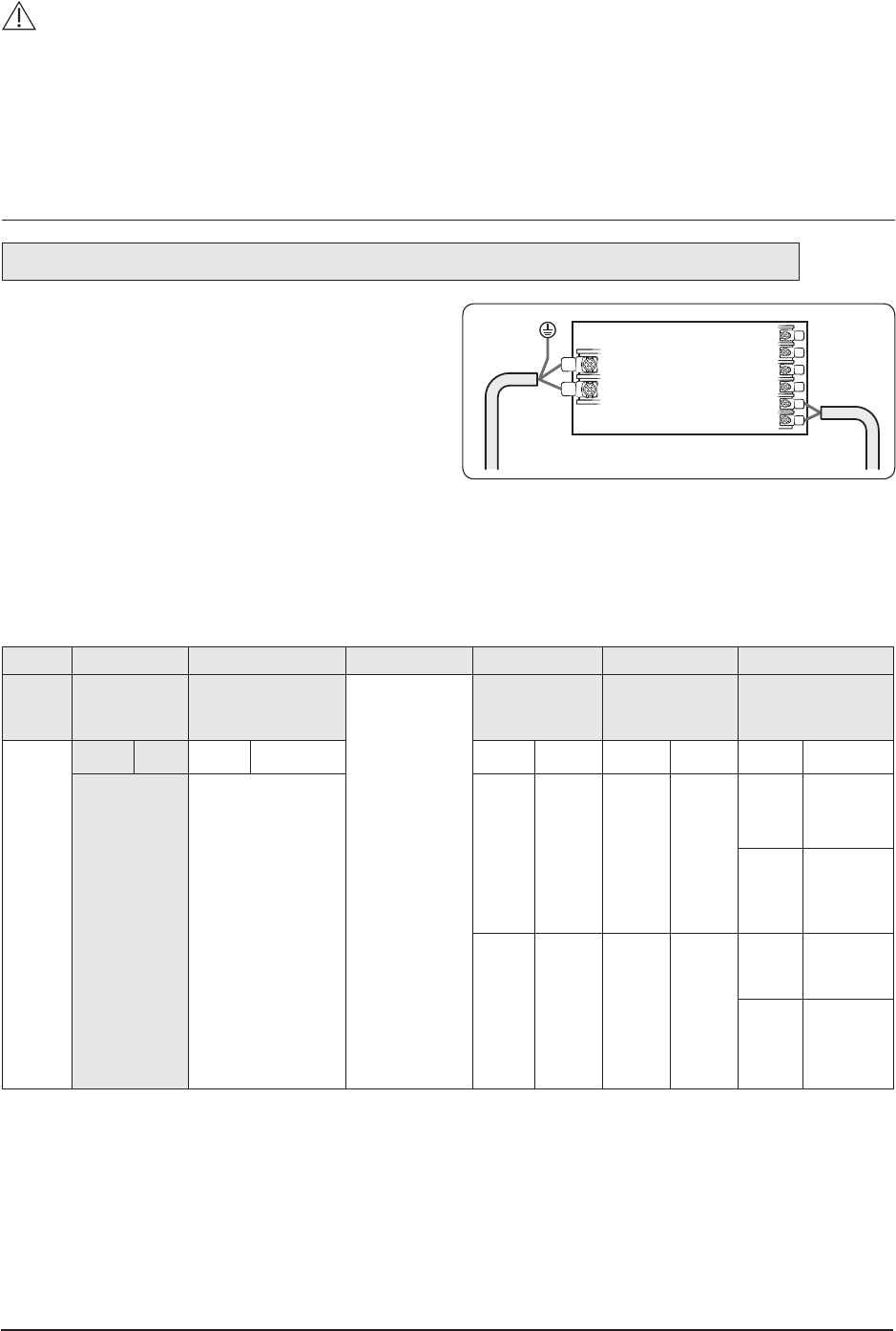
1 Make sure that the power is supplied to the indoor
unit. If the indoor unit is not plugged in, it must
include a power supply.
F1
1(L)
2(M)
F2
V1
V2
F3
F4
Indoor Unit
2 Set an address for each indoor unit using the remote control, according to your air conditioning system plan, by
referring to the following table and by following the steps in Common steps for setting the addresses and options on
page <?>.
t The indoor unit addresses (main and RMC addresses) are set to 0A0000-100000-200000-300000 by default.
t If indoor units and outdoor units match 1:1, you don’t need to set the main address because it is automatically set
by the outdoor unit.
t If you are using on or off controller, set RMC address.
Option SEG1 SEG2 SEG3 SEG4 SEG5 SEG6
Function Page Mode Setting main address
Reserved Reserved
Indoor unit
number
Indication
and details
Indication Details Indication Details Indication Details Indication Details
0A
0
No main
address
0 to 9
Units
digit
1
Main address
setting mode
Option SEG7 SEG8 SEG9 SEG10 SEG11 SEG12
Function Page
Reserved
Setting RMC address
Reserved
Group channel
(x16)
Group address
Indication
and details
Indication Details Indication Details Indication Details Indication Details
1
0
No RMC
address
RMC1 0 to 2 RMC2 0 to F
1
RMC address
setting mode
Samsung Electronics 4-7
CAUTION
t The main address must be set to a value in the range 0 to 14. If you set other values, communication error will occur.
t If any of SEG5 and SEG6 is set to a value in the range A to F, the main address of the indoor unit does not change.
t If SEG3 is set to 0, the indoor unit maintains the existing main address even if SEG6 is set to a new value.
t If SEG9 is set 0, the indoor unit maintains the existing RMC address even if SEG11 and SET12 are set to new values.
4-1-3 Setting the installation options in a batch
Option No. for an indoor unit address: 02XXXX-1XXXXX-2XXXXX-3XXXXX
1 Make sure that the power is supplied to the
indoor unit. If the indoor unit is not plugged in, it
must include a power supply.
F1
1(L)
2(M)
F2
V1
V2
F3
F4
Indoor Unit
2 Set the installation options of indoor units, by referring to the following table and by following the steps in Common
steps for setting the addresses and options on page <?>.
t The installation options of indoor units are set to 020000-100000-200000-300000 by default.
t The SEG20 option, Individual control with remote control, allows you to control multiple indoor units individually
by using the remote control.
Option
SEG1 SEG2 SEG3 SEG4 SEG5 SEG6
Function
Page Mode
Reserved
Use of external
temperature
sensor
Use of central
control
Compensation of the
fan RPM
Indication
and details
Indication
Details
Indication
Details
Indication
Details
Indication
Details
Indication
Details
02
0 Disuse 0 Disuse
0
Disuse
(recessed
installation)
1
High-ceiling
mode
(recessed
installation)
1Use1Use
4
Disuse
(exposed
installation)
5
High-ceiling
mode
(exposed
installation)

4-8 Samsung Electronics
Option
SEG7 SEG8 SEG9 SEG10 SEG11 SEG12
Function
Page Use of drain pump
Reserved Reserved Reserved Reserved
Indication
and details
Indication
Details
Indication
Details
1
0
Disuse
1
Use
2
Use with 3
minute delay
Option
SEG13 SEG14 SEG15 SEG16 SEG17 SEG18
Function
Page Use of external control
Setting the
output of
external control
S-Plasma ion Buzzer control
Maximum filter
usage time
Indication
and details
Indication
Details
Indication
Details
Indication
Details
Indication
Details
Indication
Details
Indication
Details
2
0
Disuse
Slave
(disable
Level
control*)
0
Thermo
on
0
Disuse
0
Use of
buzzer
2
1000
hours
1
On/Off
control
2
Off
control
3
Window
on/off
control
4
Disuse
Master
(enable
Level
control*)
1
Operation
on
1
Use
1
Disuse
of
buzzer
6
2000
hours
5
On/Off
control
6
Off
control
7
Window
on/off
control
Option
SEG19 SEG20 SEG21 SEG22 SEG23 SEG24
Function
Page
Individual control with
remote control
Heating setting
compensation
Reserved Reserved
Cycle time of
Swing
Indication
and details
Indication
Details
Indication
Details
Indication
Details
Indication
Details
3
0 or 1
Indoor 1
0
Default
0
34
seconds
(default)
2
Indoor 2
1 2°C 1
30
seconds
3
Indoor 3
2 5°C 2
38
seconds
4
Indoor 4

Samsung Electronics 4-9
t Even if you set the Use of drain pump (SEG8) option to 0, it is automatically set to 2 (the drain pump is used with 3 minute delay).
t If you set the Maximum filter usage time (SEG18) option to a value other than 2 and 6, it is automatically set to 2 (1000 hours).
t If you set the Individual control with remote control (SEG20) option to a value other than 0 to 4, it is automatically set to 0
(Indoor 1).
t Default value of Heating setting compensation (SEG21) is 5°C for 360 cassette model.
* Level control: The centralized controller can limit the functions and inputs of connected products with this function
enabled. (Example: Operation mode limit (Cooling only/Heating only/No limitation), Heating
temperature upper limit, Cooling temperature lower limit)
To enable 'Level control' when applying the DPM with the centralized controller, appoint the master (Set
'Use of external control [SEG14] option to 4 or higher).
Example: When installing DPM (1 Outdoor unit with 4 indoor units)
Condition SEG14 Setting
Result
External control Level control Indoor 1 Indoor 2 Indoor 3 Indoor 4
Default Not set (0) Slave (All)
Disuse Use 4 Not set (0) Not set (0) Not set (0)
Master (Indoor 1), Slave
(Indoor 2,3,4)
Use (Indoor 3) Disuse Not set (0) Not set (0) 1~3 Not set (0) Slave (All)
Use (Indoor 4) Use Not set (0) Not set (0) Not set (0) 5~7
Master (Indoor 4), Slave
(Indoor 1,2,3)
4-1-4 Changing the addresses and options individually
When you want to change the value of a specific option, refer to the following table and follow the steps in Common
steps for setting the addresses and options on page <?>.
Option SEG1 SEG2 SEG3 SEG4 SEG5 SEG6
Function Page Mode
Option mode to
change
Tens position
of the option
number
Units position
of the option
number
New value
Indication
and details
Indication
Details
Indication
Details
Indication
Details
Indication
Details
Indication
Details
Indication
Details
0D
Option
type
0 to F
Tens
position
value
0 to 9
Units
position
value
0 to 9
New
value
0 to F
Example: Changing the Buzzer control (SEG17) option of the installation options to 1 disuse.
Option SEG1 SEG2 SEG3 SEG4 SEG5 SEG6
Function Page Mode
Option mode to
change
Tens position
of the option
number
Units position
of the option
number
New value
Indication 0 D 2 1 7 1

4-10 Samsung Electronics
Abnormal condition Error code
LED Display
Error on indoor temperature sensor (Short or Open)
E121
1. Error on Eva-in sensor (Short or Open)
2. Error on Eva-out sensor (Short or Open)
3. Discharge sensor error (Short or Open)
E122
E123
E126
Indoor fan error
E154
1. Error on outdoor temperature sensor (Short or Open)
2. Error on cond sensor
3. Error on discharge sensor
Other outdoor unit sensor error that is not on the above list
E221
E237
E251
1. When there is no communication between the indoor∙outdoor units for
2 minutes
2. Communication error received from the outdoor unit
3. 3 miniute tracking error on outdoor unit
4. Communication error after tracking due to unmatching number of
installed units
5. Error due to repeated communication address
6. Communication address not confirmed
Other outdoor unit communication error that is not on the above list
E101
E102
E202
E201
E108
E109
Self diagnosis error display
1. Error due to opened EEV (2nd detection)
2. Error due to closed EEV (2nd detection)
3. Eva in sensor is detached
4. Eva out sensor is detached
5. Thermal fuse error (Open)
E151
E152
E128
E129
E198
O
1. COND mid sensor is detached
2. Refrigerant leakage (2nd detection)
3. Abnomally high temperature on Cond (2nd detection)
4. Low pressure s/w (2nd detection)
5. Abnomally high temperature on discharged air on outdoor unit
(2nd detection)
6.
Indoor operation stop due to unconfirmed error on outdoor unit
7. Error due to reverse phase detection
8. Comp stop due to freeze detection (6th detection)
9. High pressure sensor is detached
10. Low pressure sensor is detached
11. Outdoor unit copression ration error
12. Outdoor sump down_1 prevetion control
13. Compressor down due to low pressure sensor prevention control_1
14. Simultaneous opening of cooling/heating MCU SOL valve
(1st detection)
15. Simultaneous opening of cooling/heating MCU SOL valve
(2nd detection)
Other outdoor unit self-diagnosis error that is not on the above list
E241
E554
E450
E451
E416
E559
E425
E403
E301
E306
E428
E413
E410
E180
E181
O
EEPROM error
E162
EEPROM option error
E163
OOn Flickering
X
O
X
If an error occurs during the operation, an LED flickers and the operation is stopped except the LED.
X
If you re-operate the air conditioner, it operates normally at first, then detect an error again.
X
If you turn off the air conditioner when the LED is flickering, the LED is also turned off.
X
If you re-operate the air conditioner, it operates normally at first, then detect an error again.
X
When E108 error occurs, change the address and reset the system.Ex.) When address of the indoor unit #1 and #2
are set as 5, address of the indoor unit #1 will become 5 and indoor unit #2 will display E108, A002.
Detection of errors

Samsung Electronics 4-11
4-2 Troubleshooting for outdoor unit
The table below list the self-diagnostic routines. For some of error codes, you must contact an authorized service centre.
If an error occurs during the operation, it is displayed on the outdoor unit PCB LED, both MAIN PCB and INVERTER PCB.
No.
Error Code Meaning
Remarks
1 E108 Error due to duplicated communication address Check on repeated indoor unit main address
2 E121
Error on room temperature sensor of indoor unit (Short or
Open)
Indoor unit Room Thermistor Open/Short
3 E122 Error on EVA IN sensor of indoor unit (Short or Open) Indoor unit EVA_IN Thermistor Open/Short
4 E123 Error on EVA OUT sensor of indoor unit (Short or Open) Indoor unit EVA_OUT Thermistor Open/Short
5 E153 Error on float switch (2nd detection)
Indoor unit Float Switch Open/Short Drain
Pump operation Check
6 E154 Indoor fan error Check on indoor unit indoor Fan operation
7 E198 Error on thermal fuse of indoor unit (Open)
Thermal Fuse Open Check of indoor unit
Terminal Block
8 E201
Communication error between the indoor unit and outdoor
unit (Pre-tracking failure or when the actual number of indoor
units are different from the indoor unit quantity setting on the
outdoor unit)
Error due to communication tracking failure after initial power
is supplied (The error occurs regardless of the number of
units.)
Check indoor quantity setting in outdoor
9 E202
Communication error between indoor unit and outdoor unit
(When there is no response from indoor units after tracking is
completed)
Check electrical connection and setting
between indoor unit and outdoor unit
10 E203
Communication error between the outdoor unit and main
micom (For PF #4 to #6 controllers, error will be determined
from the time when the compressor is turned on.)
Check electrical connection and setting
between indoor unit MAIN PBA - INVERTER PBA
11 E221 Error on outdoor temperature sensor (Short or Open) Check Outdoor sensor Open / Short
12 E231 Error on outdoor COND OUT sensor (Short or Open) Check Cond-Out sensor Open / Short
13 E251
Error on discharge temperature sensor of compressor 1 (Short
or Open)
Check Discharge sensor Open / Short
14 E320 Error on OLP sensor (Short or Open) Check OLP sensor Open / Short
15 E403 Compressor down due to freeze protection control Check Outdoor Cond.
16 E404 System stop due to overload protection control Check Comp. when it starts
17 E416 System stop due to discharge temperature -
18
E422
Blockage detected on high pressure pipe
1. Check if the service valve is open
2. Check for refrigerant leakage (pipe
connections, heat exchanger) and charge
refrigerant if necessary
3. Check if there's any blockage on the
refrigerant cycle (indoor unit/outdoor unit)
4. Check if additional refrigerant has been
added after pipe extension
19
E425
Reverse phase or open phase Check whether 3 phase is reversed or opened.
20
E440
Heating operation restricted at outdoor temperature over
Theat_high value
HEATING
21
E441
Cooling operation restricted at outdoor temperature below
Tcool_low value
COOLING
22
E458
Fan speed error FAN1 ERROR

4-12 Samsung Electronics
No.
Error Code Meaning
Remarks
23
E461
Error due to operation failure of inverter compressor -
24
E462
System stop due to full current control -
25
E463
Over current trip / PFC over current error Check OLP sensor
26
E464
IPM Over Current(O.C) IPM
27
E465
Comp. Over load error -
28
E466
DC-Link voltage under/over error Check AC Power and DC Link Voltage
29
E467
Error due to abnormal rotation of the compressor or
unconnected wire of compressor
Check Comp wire
30
E468
Error on current sensor (Short or Open) Check Outdoor Inverter PBA.
31
E469
Error on DC-Link voltage sensor (Short or Open) -
32
E470
Outdoor unit EEPROM Read/Write error (Option) Check Outdoor EEPROM Data
33
E471
Outdoor unit EEPROM Read/Write error (H/W) Check Outdoor EEPROM PBA
34
E472
AC Line Zero Cross Signal out -
35
E473
Comp Lock error -
36
E474
Error on IPM Heat Sink sensor of inverter 1 (Short or Open) Check Outdoor Inverter PBA.
37
E475
Error on inverter fan 2 FAN2 ERROR
38
E484
PFC Overload (Over current) Error Check Outdoor Inverter PBA.
39
E485
Error on input current sensor of inverter 1 (Short or Open) Check Outdoor EEPROM PBA
40
E500
IPM over heat error on inverter 1 Check Outdoor Inverter PBA.
41 E508
Smart install is not installed -
42
E554
Gas leak detected Check the refrigerant
43
E556
Error due to mismatching capacity of indoor and outdoor unit
Check the indoor and outdoor unit capacity
45
E590
Inverter EEPROM Checksum error -
46
E660
Inverter Boot Code error -

Samsung Electronics 4-13
Indoor unit display
Symptom
In case of open or short circuit of indoor temperature sensor
Failure
Short or leakage of the corresponding sensor
Yes
No
No
In this case, is the resistance
value out of range in the temperature
table on the right?
Yes
Is indoor temperature
sensor disconnected from the
connector in PCB?
Restart the system after replacing the PCB
Restart the system after connecting
to the PCB connector
Indoor temperature sensor
failure (replace)
Remove the indoor temperature sensor
connector from the PCB and measure the
resistance between two terminals
4-3 Troubleshooting by symptoms
4-3-1 Indoor temperature sensor (open/short)
Current
temperature
(°C)
Resistance
(kΩ)
40 5.800
35 6.900
30 8.300
25 10.00
20 12.10
15 14.70
10 18.00
5 22.00
0 28.30
-5 33.90
-10 42.30
<Temperature sensor
resistance value>

4-14 Samsung Electronics
Yes
No
No
In this case, is the resistance
value out of range in the temperature table
on the right?
Yes
Is the indoor heat exchanger
temperature sensor connector disconnected
from the PCB?
Restart the system after replacing the PCB
Restart the system after
connecting the connector to PCB
Failure of the indoor heat
exchanger temperature sensor
(replace)
Remove the indoor heat exchanger
temperature sensor connector from
the PCB and measure the resistance
between two terminals
Indoor unit display
Symptom
Short or open circuit of indoor heat exchanger temperature sensor
Failure
Short or open circuit in the corresponding sensor
4-3-2 Indoor heat exchanger temperature sensor (open/short)
Current
temperature
(°C)
Resistance
(kΩ)
40 5.800
35 6.900
30 8.300
25 10.00
20 12.10
15 14.70
10 18.00
5 22.00
0 28.30
-5 33.90
-10 42.30
<Temperature sensor
resistance value>

Samsung Electronics 4-15
Indoor unit display
Symptom
Indoor unit fan does not run /Runs at excessive high speed and stops
Failure
Check if the motor connector is disconnected/ check the motor fan assembly status
4-3-3 Indoor FAN error
Yes
No
Yes
Is there foreign substance
stuck in the motor fan?
Yes
Is the motor connector
disconnected from the PCB?
Replace the PCB and restart the unit
Connect the connector to
PCB and restart the unit
Remove the foreign substance
and restart the unit

4-16 Samsung Electronics
Indoor unit display
Symptom
Communication error between the indoor and outdoor unit for two minutes
Failure
Communication error between the indoor unit and outdoor unit
4-3-4 Communication error after finishing Tracking
No
Yes
No
Yes
Is there a response from the indoor PCB?
(LED01 (RED) is not ON)
In this case, is the
voltage waveform between the lines square
wave with amplitude over ±0.7V as shown
in the following picture?
+0.7V
-0.7V
Good
Bad
Check the communication cable and
replace the indoor unit PCB
Remove the communication cable
connecting the outdoor unit to indoor unit,
and measure the signal on LINE 2 of the
outdoor unit with a scope
Reconnect the cable connecting
the outdoor unit to the indoor unit
and restart the unit.
If the communication still doesn’t work,
replace the indoor unit PCB.
Check the communication
cable in the outdoor unit PCB
and replace the PCB
LED01
Samsung Electronics 4-17
Indoor unit display
Symptom
The indoor unit floating sensor is open and that state is maintained for more than one minute
Failure
Increase in the drain pan water level due to failure of the indoor unit drain pump,
or float sensor failure
4-3-5 Indoor unit float sensor error
No
No
No
No
No
Yes
Yes
Yes
Yes
Yes
Yes
Remove the floating sensor
connector connected to the indoor unit
PCB and the resistance measured between the
two terminals. Is the resistance ∞?
(open circuit)
Is the water level in the drain pan high?
Does drain pump operate
when compressor operates?
Same error occurs again
No
Drain pump PCB
Is the terminal voltage around
AC 220V?
Is the water level in
drain pan decreasing?
Reset the indoor unit power and
check the operation of the drain pump.
(it vibrates when operating)
Normal operation
Replace the indoor unit PCB
Reassemble the floating sensor
connector and reset the outdoor unit
power. (Indoor unit power reset is
required)
Normal operation
Replace the floating sensor
when it fails and reset the
indoor unit power
Replace the drain pump
Replace the drain pump Replace the indoor unit PCB
Error occurs
t 'MPBUTFOTPSFSSPSJTDMFBSFEPOMZ
when the indoor power is reset

4-18 Samsung Electronics
Restart the unit after replacing the PCB
Indoor unit display
Symptom
EEPROM circuit failure
Failure
EEPROM component failure, EEPROM circuit parts missing/damaged/soldering failure
4-3-6 EEPROM circuit failure
No
Yes
Are the EEPROM circuit
components in good conditions?
(missing components / damage /
soldering failure)
Replace the PCB if the restart fails

Samsung Electronics 4-194-19
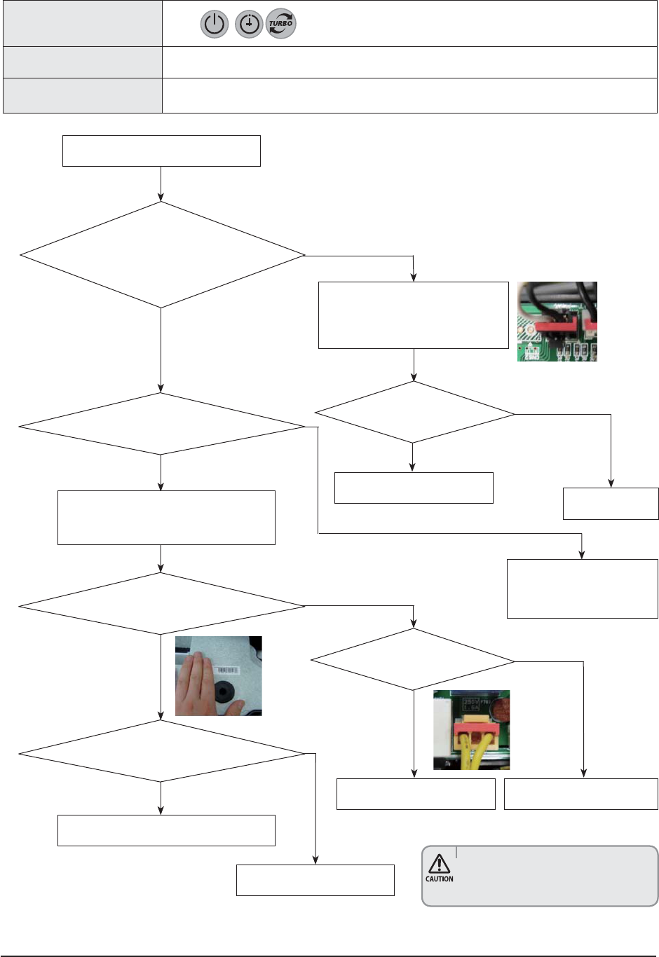
4-3-7 Outdoor unit is not powered on – Initial diagnosis
1. Check items
1) Is the power supply voltage 220V?
2) Is the AC power connected correctly?
3) Are the LEDs in the main PCB and inverter PCB of the outdoor unit ON?
4) Is the input power voltage of the indoor unit 220V?
5) Is the wired remote controller connected correctly?
2. Check procedure
Yes
Turn off the main power switch
(circuit break of power outlet) and turn on
again after 30 seconds.
Check the input power
No
Is the outdoor unit power
supply (L-N) 220V?
Yes
Check the connection of the terminal block
No
Is the outdoor unit power
voltage (L-N) 220V?
Yes
Replace the inverter PBA
No
Is the voltage between
the terminal 2 (~) and 4 (~) of the
bridge diode 220V?
Yes
Replace the fuse
No
Is the fuse connected?
Yes
Replace the inverter PBA
No
Is the resistance value of R001 200Ω?
Cont.

4-20 Samsung Electronics
Yes
Outdoor unit is not powered on – Initial diagnosis (cont.)
Yes
Connect the reactor
No
Is the reactor connector
connected correctly?
Replace the PBA.
Cont.

Samsung Electronics 4-21
4-4-1 Communication error
1. 1.Checklist :
1) Is the cable between the indoor unit and outdoor unit connected correctly?
2) Isn't the power cable and communication cable cross?
2. Troubleshooting procedure
Yes
Restart after power off.
Terminate the service
Exchange the indoor unit PBA.
No
Is the communication error occurred again?
Yes
Correct the wrong cable
No
Is the connection of power cable and
communication cable normal?
Yes
Exchange the PBA of no power unit
No
Is the power is normal?
(check the LED Lamp
Yes
Yes
Terminate the service.
No
Is the communication error occurred again?
Exchange the outdoor unit PBA.

4-22 Samsung Electronics
4-4-2 Outdoor temperature sensor error
1. 1.Checklist :
1) Is the cable between the indoor unit and outdoor unit connected correctly?
2) Is the sensor placed correctly?
3) Does the both terminal of sensor satisfy the resistance value in accordance with temperature?
4) Is the resistance value of sensor connection pull-up correct?
Yes
Reconnect the sensor connector.
Micom error or connector check
No
Is the sensor resistance value #1-#2
10kohm±3% at the room temperature
of 25°C
Is the sensor connector(CN251) connected
correctly in accordance with a color(BLU,6PIN)?
Sensor Replace
Sensor resistance value : 20°C - 12.09kohm
30°C - 8.31kohm
35°C - 6.94kohm
40°C - 5.83kohm
No
No
Exchange the PBA of no power unit
Yes
Below 0.5V or Over 4.5V?
Yes
Connect the sensor to PBA connector (6pin)
supply power and measure the voltage of
#1-#2 in the connector
Exchange the Outdoor PBA
Yes
4-4-2-1. Troubleshooting procedure (PF2)

Samsung Electronics 4-23
4-4-2-2. Troubleshooting procedure (PF3)
Yes
Reconnect the sensor connector.
Micom error or connector check
No
Is the sensor resistance value #1-#2
10kohm±3% at the room temperature
of 25°C
Is the sensor connector(CN502) connected
correctly in accordance with a colorRED,4PIN)?
Sensor Replace
Sensor resistance value : 20°C - 12.09kohm
30°C - 8.31kohm
35°C - 6.94kohm
40°C - 5.83kohm
No
No
Exchange the PBA of no Ourdoor PBA
Yes
Below 0.5V or Over 4.5V?
Yes
Connect the sensor to PBA connector (4pin)
supply power and measure the voltage of
#1-#2 in the connector
Exchange the Outdoor PBA
Yes

4-24 Samsung Electronics
4-4-3 Outdoor Coil temperature sensor error
1.Checklist :
1) Is the sensor connected correctly?
2) Is the sensor placed correctly?
3) Does the both terminal of sensor satisfy the resistance value in accordance with temperature?
4) Is the resistance value of sensor connection pull-up correct?
4-4-3-1. Troubleshooting procedure (PF2)
Yes
Reconnect the sensor connector.
Micom error or connector check
No
Is the sensor resistance value #5-#6
10kohm±3% at the room temperature
of 25°C
Is the sensor connector(CN251) connected
correctly in accordance with a color(BLU,6PIN)?
Sensor Replace
Sensor resistance value : 20°C - 12.09kohm
30°C - 8.31kohm
35°C - 6.94kohm
40°C - 5.83kohm
No
No
Exchange the Outdoor PBA
Yes
Below 0.5V or Over 4.5V?
Yes
Connect the sensor to PBA connector (6pin)
supply power and measure the voltage of
#5-#6 in the connector
Exchange the Outdoor PBA
Yes

Samsung Electronics 4-25
4-4-3-2. Troubleshooting procedure (PF3)
Yes
Reconnect the sensor connector.
Micom error or connector check
No
Is the sensor resistance value #3-#4
(CN501) 10kohm±3% at the room temperature
of 25 25°C
Is the sensor connector(CN501) connected
correctly in accordance with a colorRED,4PIN)?
Sensor Replace
Sensor resistance value : 20°C - 12.09kohm
30°C - 8.31kohm
35°C - 6.94kohm
40°C - 5.83kohm
No
No
Exchange the Outdoor PBA
Yes
Below 0.5V or Over 4.5V?
Yes
Connect the sensor to PBA connector(4pin)
supply power and measure the voltage of
#3-#4 in the connector
Exchange the Outdoor PBA
Yes

4-26 Samsung Electronics
4-4-4 Outdoor Discharge temperature sensor error
1.Checklist :
1) Is the sensor connected correctly?
2) Is the sensor placed correctly?
3) Does the both terminal of sensor satisfy the resistance value in accordance with temperature?
4) Is the resistance value of sensor connection pull-up correct?
4-4-4-1. Troubleshooting procedure (PF2)
Yes
Reconnect the sensor connector.
Micom error or connector check
No
Is the sensor resistance value #3-#4
10kohm±3% at the room temperature
of 25°C
Is the sensor connector(CN251) connected
correctly in accordance with a color(BLU,6PIN)?
Sensor Replace
Sensor resistance value : 20°C - 242kohm
30°C - 166ohm
35°C - 138ohm
40°C - 115kohm
No
No
Exchange the Outdoor PBA
Yes
Below 0.5V or Over 4.5V?
Yes
Connect the sensor to PBA connector (6pin)
supply power and measure the voltage of
#3-#4 in the connector
Exchange the Outdoor PBA
Yes

Samsung Electronics 4-27
Sensor Replace
Sensor resistance value : 20°C - 242kohm
30°C - 166ohm
35°C - 138ohm
40°C - 115kohm
4-4-4-2. Troubleshooting procedure (PF3)
Yes
Reconnect the sensor connector.
Micom error or connector check
No
Is the sensor resistance value #3-#4
(CN501) 10kohm±3% at the room temperature
of 25 25°C
Is the sensor connector(CN502) connected
correctly in accordance with a colorRED,4PIN)?
No
No
Exchange the Outdoor PBA
Yes
Below 0.5V or Over 4.5V?
Yes
Connect the sensor to PBA connector(4pin)
supply power and measure the voltage of
#3-#4 in the connector
Exchange the Outdoor PBA
Yes

4-28 Samsung Electronics
4-4-5 Outdoor Discharge over temperature error
1.Checklist :
1) Check the discharge temperature in the outdoor unit
2) Check the compressor locking or gas leak
3) 3) Download the EEPROM data
2. Troubleshooting procedure
Yes
Yes
Terminate the service
Exchange the Outdoor PBA
Download the EEPROM data
No
Is the discharge over temperature sensor error
appeared again?
Terminate the service
No
No
Terminate the service
Is the discharge over temperature sensor error
appeared again?
Is the discharge over temperature sensor error
appeared again?
The condition is too poor for air conditioner to
operate
Wait until discharge temperature is decreased
Exchanged the Compressor
Restart after power off.
Yes
after 30min ~ 1Hr

Samsung Electronics 4-29
4-4-6 Outdoor Fan motor error
1.Checklist :
1) Are the input power voltage and the power connection correct?
2) Is the motor wire connected to the outdoor PBA correctly?
3) Is there no assembly error or none-assembly in the terminal of motor wire connector?
4) Is there no obstacle at the surrounding of motor and propeller?
2. Troubleshooting procedure
Yes
Yes
Power off and Separate the Fan motor wire
from CN901 on Outdoor PBA
PBA problem or Motor problem
Change the PBA first and check the operation
No
Yes
Does the fan rotate?
Terminate the service
Exchange the Fan motor
No
No
No
Follow the check procedure of outdoor unit
power supply error check
Exchange the Outdoor PBA
Is the fan error appeared again?
Is there short among each pin #1~#6
Is the voltage of CN901 #3-#5 and #3-#6 with in
1Vdc~15Vdc during the operation?
Is the voltage of CN901 #1-#3 over 250Vdc
Reassemble the fan wire and input the power
again
Exchange the Fan motor
Restart after power off.
Yes
No

4-30 Samsung Electronics
4-4-7 Compressor starting error
1.Checklist :
1) Is the connection of cable for the compressor?
2) Is the compressor wire is connected clockwise? U(RED)-V(BLU)-W(YEL)
3) Is the interphase resistance of compressor normal?
2. Troubleshooting procedure
Terminate the service
Download the EEPROM data
No
Is the restart error occurred again?
Is the connection of compressor wire is
normal?
Connect the comp wire normally
No
No
No
Yes
Terminate the service
Exchange the Outdoor PBA
Is the restart error occurred again?
Is the compressor body and interphase
resistance insulated?
Exchanged the Compressor
Restart after power off.
Yes
Yes
Yes

Samsung Electronics 4-31
4-4-8 Compressor wire missing error/rotation error
1.Checklist :
1) Is the connection of cable for the compressor?
2) Is the compressor wire is connected clockwise? U(RED)-V(BLU)-W(YEL)
3) Is the interphase resistance of compressor normal?
2. Troubleshooting procedure
Terminate the service
No
Is the restart error occurred again?
Is the connection of compressor wire is
normal? (PBA and Compressor)
Connect the comp wire normally
No
No
No
Yes
Terminate the service
Exchange the Outdoor PBA
Is the restart error occurred again?
Is the compressor body and interphase
resistance insulated?
Exchanged the Compressor
Restart after power off.
Yes
Yes
Yes

4-32 Samsung Electronics
4-4-9 O.C(Over Current) error
1.Checklist :
1) Is the IPM Shunt(PF2:R451,R452,R453,PF3:R413,R414,R415) resistance value correct? Check the resistor is opened
2) Is the condition of surrounding temperature abnormal overload?
3) Is there any problem as like the temperature sensor separation or measurement value error?
4) Is the interphase resistance of compressor normal?
2. Troubleshooting procedure
Is the O.C error occurred?
Is the connection of compressor wire is
normal?
No
No
Yes
No
No
No
No
No
Yes
Exchange the Outdoor PBA
Correct the sensor position or exchange the
sensor
Is the O.C error
occurred again?
Terminate the service
Restart after returning to the normal load
Terminate the service
Connect the comp wire normally
Terminate the service
Is the restart error occurred again?
Is the condition of indoor/outdoor
temperature normal load?
Is the position of temperature sensor and
sensing value normal?
Is the compressor body and interphase
resistance insulated?
Exchanged the Compressor
Restart after power off.
Yes
Yes
Yes
Yes
Yes

Samsung Electronics 4-33
4-4-10 DC_link voltage sensor error
1.Checklist :
1) Is the input voltage of outdoor terminal block is normal?
2) Is the reactor wire connected?
3) Is the DC_link capacitor(PF2:CE101,CE102,CE103,PF3:CE001,CE002,CE003,CE004)) assembled in accordance the specification?
(Outdoor PBA)
4) Is the DC_link resistor(PF2:R104,R106,R107,R108,PF3:R004,R005,R006,R007) value is normal? (Outdoor PBA)
2. Troubleshooting procedure
Connect the reactor wire
No
Is the connected of reactor wire?
(PBA-Reactor)
Is the DC_link voltage (CE101 or CE001) is
normal in operation mode?
Normal range(280Vdc~320Vdc)
Check the power input
No
No
No
No
Exchange the Outdoor PBA
Exchange the Outdoor PBA
Is the DC_link sensing voltage(R104 or R004) is normal in
operation mode?
Normal range (0.2Vdc~2.8Vdc)
Is the reactor insulation damaged?
Exchange the Reactor
Restart after power off.
Start the operation (cooling mode or heating
mode)
Yes
Yes
Yes

4-34 Samsung Electronics
4-4-11 DC_link voltage under/over error, Over voltage protection error/PFC over load
1.Checklist :
1) Is the input voltage of outdoor terminal block is normal?
2) Is the reactor wire connected?
3) Is the reactor wire connected?
4) Is the DC_link capacitor(PF2:CE101,CE102,CE103,PF3:CE001,CE002,CE003,CE004)) assembled in accordance the specification? (Outdoor PBA)
5) Is the DC_link resistor(PF2:R104,R106,R107,R108,PF3:R004,R005,R006,R007) value is normal? (Outdoor PBA)
2. Troubleshooting procedure
Connect the reactor wire
No
Is the connected of reactor wire?
(PBA-Reactor)
Is the the input voltage is nomal?
Normal range(180Vac ~ 270Vac)
Is the reactor insulation damaged?
Check the input power in the powercord.
No
No
No
No
Check the input power
Exchange the Outdoor PBA
Exchange the Outdoor PBA
Is the DC_link voltage (CE101 or CE001) is normal in operation
mode?
Normal range(280Vdc~320Vdc)
Is the DC_link sensing voltage(R104 or R004) is normal in
operation mode?
Normal range (0.2Vdc~2.8Vdc)
Exchange the Reactor
Restart after power off.
Restart after power off.
Start the operation (cooling mode or heating
mode)
Yes
Yes
Yes
Yes
Yes
Yes

Samsung Electronics 4-35
4-4-12 DC_link voltage sensor error
1.Checklist :
1) Is the PFC Shunt(PF2:R062,R063,PF3:R807,R808,R809) resistance value correct? Check the resistor is opened
2) Is the condition of surrounding temperature abnormal overload?
3) Is there any problem as like the temperature sensor separation or measurement value error?
4) Is the interphase resistance of compressor normal?
2. Troubleshooting procedure
Restart after returning to the normal load
No
Yes
Is the condition of indoor/outdoor
temperature normal load?
Is the I_trip error
occurred again?
Terminate the service
No
No
No
No
Correct the sensor position or exchange the
sensor
Correct the cable connection
Is the position of temperature sensor and the sensing value
normal?
Is the connection cable for the compressor and
power terminal normal?
Exchange the Outdoor PBA
Restart after power off.
Yes
Yes
Yes

4-36 Samsung Electronics
4-4-13 Current sensor error/Input current sensor error
1.Checklist :
1) Is the PFC Shunt(PF2:R062,R063,PF3:R807,R808,R809) resistance value correct? Check the resistor is opened
2) Is the IPM Shunt(PF2:R451,R452,R453,PF23:R413,R414,R415) resistance value correct? Check the resistor is opened
3) Is there no short or open around IC451(PF2) or IC451,IC452(PF3)?
2. Troubleshooting procedure
Exchange the Outdoor PBA
No
Is the PFC shunt and IPM shunt resistance
value correct?
No
Terminate the service
Is the current sensor error appeared again?
Exchange the Outdoor PBA
Restart after power off.
Yes
Yes
Yes

Samsung Electronics 4-37
4-4-14 Heatsink sensor error/Heatsink over heat
1.Checklist :
1) Are there screws assembly in PBA-heatsink?
2) Is the gap PBA-heatsink
3) Is the fan operation normal?
4) Is the cover assembly in control-box normal?
2. Troubleshooting procedure
Fastening the screw
No
Are there screws in PBA-heatsink?
(4 screws)
No
Check the fan connection
Change the Fan motor
Is the fan operation normal?
Exchange the Outdoor PBA
Restart after power off.
Yes
Yes
Yes

4-38 Samsung Electronics
4-4-15 Comp Vlimit error/Comp current limit error
1.Checklist :
1) Is the PFC Shunt(PF2:R062,R063,PF3:R807,R808,R809) resistance value correct? Check the resistor is opened
2) Is the condition of surrounding temperature abnormal overload?
3) Is there any problem as like the temperature sensor separation or measurement value error?
4) Is the interphase resistance of compressor normal?
2. Troubleshooting procedure
Terminate the service
Exchange the Outdoor PBA
No
No
Yes
IIs the O.C error occurred?
Is the O.C error occurred
again?
Terminate the service
No
No
No
No
No
No
Connect the comp wire normally
Terminate the service
Correct the sensor position or exchange the
sensor
Restart after returning to the normal load
Is the connection of compressor wire is
normal?
Is the O.C error occurred again?
Is the condition of indoor/outdoor
temperature normal load?
Is the position of temperature sensor and
sensing value normal?
Is the compressor body and interphase
resistance insulated?
Exchange the Outdoor PBA
Restart after power off.
Yes
Yes
Yes
Yes
Yes
Yes

Samsung Electronics 4-39
4-4-16 EEPROM error/OTP error
1.Checklist :
1) Is there a short around micom?
2) Is there a short around IC202(PF2) or IC701(PF3)?
3) Did you download or insert EEPROM IC, after changing outdoor PBA?
2. Troubleshooting procedure
Terminate the service
No
Is the error appeared again?
Exchange the Outdoor PBA
power off and download EEPROM data
(or. Insert the service EEPROM IC)
Yes

4-40 Samsung Electronics
4-4-17 AC zero cross signal error
1.Checklist :
1) Check the power condition at customer's house (Is there any power noise?)
2) Have been there power failure?
2. Troubleshooting procedure
Terminate the service
No
Is the AC line zero cross signal error appeared
again?
Exchange the Outdoor PBA
Yes

Samsung Electronics 4-41
4-4-18 Operation condition secession error
1.Checklist :
1) Check the temperature around the outdoor unit.
2. Troubleshooting procedure
Terminate the service
No
Is the operation condition secession error
appeared again?
* Heating mode *
Is the outdoor temperature over 40°C or under
-30°C?
* Cooling mode *
Is the outdoor temperature under °C?
The temperature condition is too poor to operate.
Wait until temperature is changed
Yes
Yes

4-42 Samsung Electronics
4-4-19 Capacity miss match error
1.Checklist :
1) Check the Btu between indoor and outdoor unit
2) Check the indoor unit option and outdoor unit EEPROM data
2. Troubleshooting procedure
Exchange the one of them according to the
exact model spec
Terminate the service
Terminate the service
No
No
No
Is the capacity miss match error appeared
again?
Is the capacity miss match error appeared
again?
Is the rated Btu between indoor unit and
outdoor unit?
Download the EEPROM data
Exchange the Outdoor PBA
Exchange the Indoor PBA
Reset the option code again at indoor unit
Yes
Yes
Yes
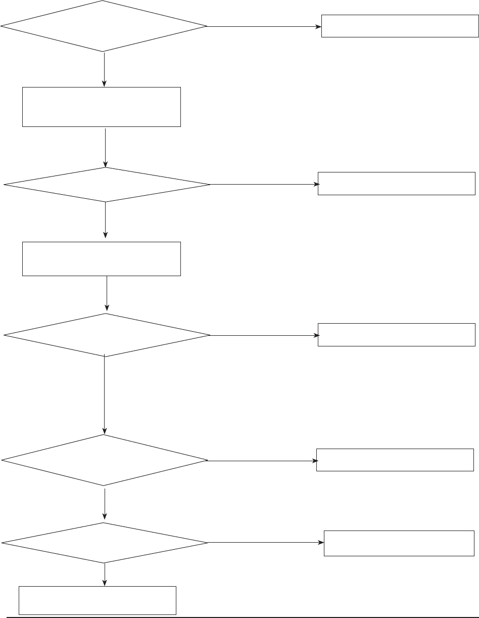
Samsung Electronics 4-43
4-4-20 Gas leak error
1.Checklist :
1) Is the position of indoor Eva_in sensor normal?
2) Check the pipe crack
3) Check the EEV valve connection in Outdoor unit
4) Check the refrigerant was charged
2. Troubleshooting procedure
Indoor sensor take the normal position
Check the pipe crack.
Fill up the refrigerant.
No
No
Is the position of indoor eva_in sensor normal?
No
No
No
Terminate the service.
Change the EEV valve
Connect the EEV valve.
Is the gas leak error appeared again?
Is the EEV valve connection normal?
Is the EEV valve is operation?
Check the sound of EEV valve after power on.
Is the pressure of refrigerant normal?
Exchange the Indoor PBA
Exchange the Outdoor PBA
Check the EEV valve operation.
Yes
Yes
Yes
Yes
Yes
Yes
Yes

Samsung Electronics 5-1
5. PCB Diagram
5-1 Indoor Unit
MAIN PCB
■ AC012MNADCH / AC018MNADCH / AC024MNADCH / AC030MNTDCH / AC036MNTDCH
4 5 6 7 8
10
8
11
12
13
1
2
3

5-2 Samsung Electronics
#1 : L
#2 : NOT USED
#3 : N
#1~2 : COMMUNICATION SIGNAL #1 : DC 310V
#2 : NOT USED
#3 : GND
#4 : PWM SIGNAL
#5 : FEEDBACK SIGNAL
#1 : THERMAL FUSE SIGNAL
#2 : GND
#1~2 : GND
#3 : SPI CONTROL SIGNAL
#4 : NOT USED
#1 : DC 12V
#2~5 : LOUVER SIGNAL
#1~4 : EEV SIGNAL
#5~6 : DC 12V
#1 : OOM TEMPERATURE SENSOR
SIGNAL
#2 : GND
#1 : EVA IN TEMPERATURE SENSOR
SIGNAL
#2 : GND
#3 : EVA OUT TEMPERATURE SENSOR
SIGNAL
#4 : GND
#5 : DISCHARGE TEMPERATURE SENSOR
SIGNAL
#6 : GND
#1~3 : LED SIGNAL
#4 : REMOCON SIGNAL
#5 : GND
#6 : DC 5V
#7~8 : REMOCON SIGNAL
#9~11 : NOT USED
#1 : GND
#2 : NOT USED
#3 : DC 5V
#4~7 : EEPROM SIGNAL
#1~8 : DOWNLOAD SIGNAL
#9 : GND
#10~11 : DC 5V
#12~16 : DOWNLOAD SIGNAL
#17 : GND
#18~20 : DOWNLOAD SIGNAL
#1~2 : COMMUNICATION SIGNAL
#3~4 : SUB PBA SIGNAL
#5 : EXTERNAL CONTROL SIGNAL
#6 : COMP CHECK SIGNAL
#7 : ERROR CHECK SIGNAL
#8 : DC 5V
#9 : GND
#10 : DC 12V
#11~14 : COMMUNICATION SIGNAL
CNP101-POWER CN303-COM1 CN701-BLDC FAN CN140-FUSE CHECK
CN805-SPI CN802-STEP UP/DOWN CN801-EEV CN401-ROOM
CN403-EVA IN/OUT/DIS CN501-DISPLAY CN201-EEPROM CN302-DOWNLOAD
CN301-to 2WIRE SUB

Samsung Electronics 5-3
■ Sub PCB
1
#1,#2,#19,#20:COMM. SIGNAL
#3,#18:EXTERNAL CONTROL
#4,#17:COMP CHECK
#5,#16:ERROR CHECK
#6:VCC(DC5V)
#7,#14:GND
#8,#13,#15:DC12V
#9~#12:COMM. SIGNAL
CN1-2WIRES COMM.

5-4 Samsung Electronics
5-2 Outdoor Unit
■ AC012KXADCH
Main PCB
NO Description
1 SMPS POWER: YW396-03AV BLU
2 4WAY:YW396-03AV WHT
3 REACTOR:DBT081-2P WHT
4 BLDC FAN:YW396-06V WHT
5 COMM:YW396-02V RED
6 SUB PBA POWER:SMW200-05P BLK
7 EEV1:SMW250-05 RED
8 COMP:DBT061-3P WHT
9 SMPS: SMW250-03 BLU
10 EEPROM:B7P-MQ WHT
11 TEMP SENSOR: SMW200-08P WHT
12 MAIN DOWNLOAD:YDW200-20 BLK
13 SUB PBA: SMW200-10P BLK
14 DRED:SMW250-05 WHT
15 INV DOWNDOWN: YDAW200-20TR BLK
16 SUB PBA: SMW200-10P WHT
17 ENABLE CGND: SMW250-03 RED
1 3 5 6 8 10121315
2
4
7
9
11 14
16
17

Samsung Electronics 5-5
QAC018JXADCH
Main PCB
5 4 3 2 1 76 8 9 10 11 12

5-6 Samsung Electronics
CN030 : 4WAY VALVE
CN951 : SIGNAL TO SUB PCB
CN252 : THERMISTOR
CN851:S-NET Communication
CN701 : EEV
CN901 : BLDC MOTOR
CN302:Communication(COM1)
CN551: Downloader
CN251 : THERMISTOR
CN451 : COMP POWER
CN201 : Downloader
CN051 : Reactor
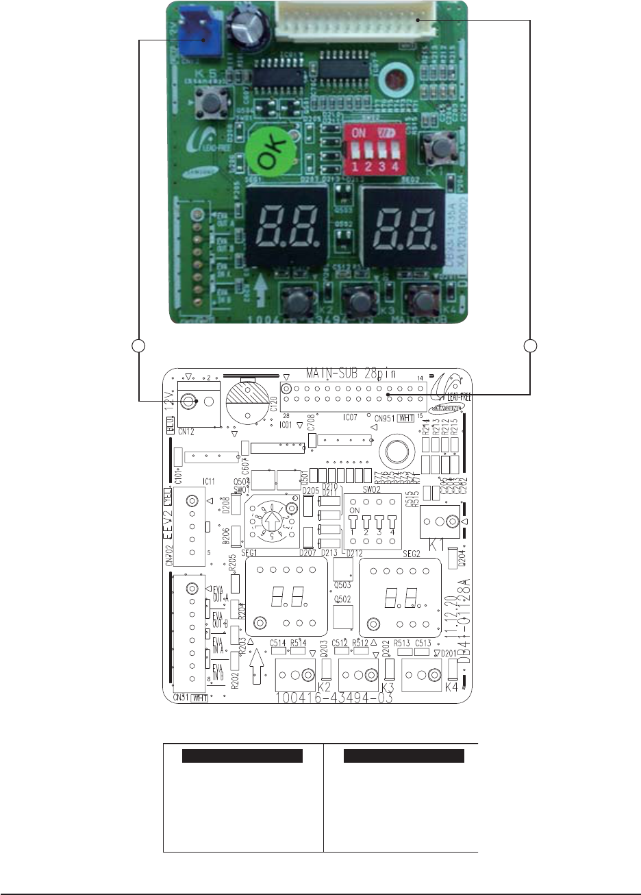
Samsung Electronics 5-7
QAC018JXADCH
SUB PCB
1 2
CN12 : DC12V
CN951 : SIGNAL TO MAIN PCB

5-8 Samsung Electronics
20 19 18 17 16 15 1314 12
11
10
9
8
765
1
2
3
4
No Part Code Local Function Description
1 3711-003404 CN703 BASE-HEATER YW396-03AV BLU
2 3711-003406 CN702 4WAY-1 YW396-03AV YEL
3 3711-003407 CN701 HOTGAS YW396-03AV RED
4 3711-000203 CN101 POWER YW396-03AV WHT
5 3711-002001 CN306 DOWNLOAD YDW200-20P BLK
6 3711-007817 CN806 EEPROM B7P-MQ WHT
7 3711-000024 CN501 MODE SELECTOR SMW250-03 WHT
8 DB65-00320A CN304 DRED DAPC-2009-6P BLK
9 3711-000744 CN103 EARTH YDW236-01 WHT
10 3711-000177 CN303 COMM-INDOOR YW396-02V RED
11 3716-001162 CN003 QUIET S/W BR-7623-2P BLK
12 3711-005096 CN302 COMM-OPTION SMW200-05 BLK
13 3711-007069 CN402 HIGH PRESSURE S/W B04B-XARK-1 RED
14 3711-007325 CN401 LOW PRESSURE S/W B04B-XARK-1 BLU
15 3711-001038 CN305 COMM INV SMW250-06 WHT
16 3711-000939 CN801 ERROR/COMP CHECK SMW250-04 RED
17 3711-000176 CN12 DC12V YW396-02V BLU
18 3711-000997 CN803 EEV1 SMW250-05 BLU
19 3711-001036 CN802 EEV4 SMW250-06 BLU
20 3711-001084 CN403 OUT TEMP/COND/DISQ/OLP SMW250-08 WHT
QAC024JXADCH / AC030JXADCH, AC036JXADCH
MAIN PCB

Samsung Electronics 5-9
2
3 4
6
5 8
7
1
QAC024JXADCH / AC030JXADCH, AC036JXADCH
INVERTER PCB
Reactor-A1/B1 Reactor-A2/B2
CN50(2PIN/RED)-Communication
CN22-Downloader
CN21-DAC/ENCODER
CN91-FAN2
CN90-FAN1
CN71-COMP.

5-10 Samsung Electronics
QAC024JXADCH / AC030JXADCH / AC036JXADCH
3 1
2
EMI PCB
L1-AC POWER L phase N1-AC POWER N phase CN01-AC POWER

Samsung Electronics 6-1
This Document can not be used without Samsung’s authorization.
6. Wiring Diagram
6-1 Indoor Unit

6-2 Samsung Electronics
6-2 Outdoor Unit
This Document can not be used without Samsung’s authorization.
■
AC012KNLDCH


6-4 Samsung Electronics
QAC024JXADCH / AC030JXADCH / AC036JXADCH
This Document can not be used without Samsung’s authorization.

Samsung Electronics 7-1
7. Preference Sheet
7-1 Index of Model Name
Model Code
"/" can be removed from the buyer card if there are not enough digits.
Product Type
AM DVM
AJ PMA
AC CAC (USD) / ASD
AE EHS
AN VTL
AK
PAK
(Packaged System)
AG CHR
Feature
S General Set (NASA)
N Indoor unit (NASA)
X Outdoor unit (NASA)
A General Set (Non-NASA)
B
Indoor unit (
Non-
NASA)
C
Outdoor unit (
Non-
NASA)
Feature
F FLAGSHIP
P PREMIUM
D DELUXE <- Basic
S STANDARD
Capacity
1 BTU/H(*100)
2 CMH(*10)
3 HP(/10)
4 WATT(*100)
Power
A A(115V, 60hz, 1Ф)
B B(220V, 60Hz, 1Ф)
C C(208~230V, 60Hz)
D D(200~220V, 50Hz)
E E(220~240V, 50Hz)
F F(208~230V, 60Hz, 3Ф)
G G(380~415V, 50Hz, 3Ф)
H H(380V, 60Hz, 3Ф)
J J(460V, 60Hz, 3Ф)
K K(220~240V, 50/60Hz, 1Ф)
M M(127V, 50Hz)
N N (380~415V, 50/60Hz, 3Ф)
Year
E 2012
F 2013
H 2014
J 2015
K 2016
M 2017
Buyer NameCapacity
Series
C
COOLING ONLY
R410a
H
HEAT PUMP
R
HEAT RECOVERY
D
COOLING ONLY
R22
E
HEAT PUMP
A
Cooling only
R134A
B
Heat Pump
N
N/A
H
C
H
0
H
1
H
2
H
M
H
N
H
A
H
D
H
C
H
H
H
/
H
A
H
A
H
A
Feature
Code Type
Remark
1 1 Way CST
CST
2 2 Way CST
N Mini 4 Way CST
4 4 Way CST
H HSP Duct
Duct
M MSP Duct
L LSP Duct
E Fresh Air Intake Duct
G
Ceiling Conceiled
Duct
C Ceiling
ETC
J Console
F Floor Mounting
PFAC
FAC/PAC
V RAC-Jungfrau
RAC
Q RAC-Neo Forte(EEV)
T RAC-Neo Forte
D RAC-Domestic
R RAC-Maldive
A
RAC-New Model
(Slim)
7 RAC-Vivace

7-2 Samsung Electronics
■ CONDENSER
High temperature and high pressure gas state coolant discharged from the compressor is converted to a liquid state as it is cooled
down by the heat emission in the outdoor condenser unit, and sent to the evaporator.
■ COMPRESSOR
Low temperature and low pressure coolant is compressed and sent to the cycling system
■ EVAPORATOR
Liquid coolant sucked in through the capillary tubes cools down the room by absorbing the surrounding heat as it evaporates
(converting from liquid to gas). (Absorbing heat required for evaporation)
■ SERVICE VALVE
You can open the valve by turning the need valve counterclockwise using hex wrench, and it is used for vacuum, gas purging, coolant
injection, coolant purging, and indoor-outdoor unit connection.
■ ACCUMULATOR
Accumulator prevents the flow of liquid-state coolant into the compressor. (Liquid-state coolant flowing into the compressor will
overload the compressor.)
Indoor Unit
Outdoor Unit
Heat exchanger
Evaporator
Liquid pipe
Gas pipe
3-way valve
3-way valve
Electronic expansion valve
Compressor
Oil separator
4-way valve
Cooling
Heating
Leak check points
Aux accumulator
Fan
Heat exchanger
Evaporator
Fan
7-2 Refrigerating Cycle Diagram

This Service Manual is a property of Samsung Electronics Co., Ltd.
Any unauthorized use of Manual can be punished under applicable
International and/or domestic law.
© Samsung Electronics Co., Ltd. Mar. 2017.
Printed in China.
