
International Palladiom Keypad Installation Best Practices
Application Note #705
Revision B
February 2020
1 Customer Assistance — 1.844.LUTRON1
Overview
Once installed, the Palladiom keypad is a beautiful wall control designed to be elegant and discreet. To ensure the
best installation possible, this document outlines the international Palladiom keypad installation best practices.
Table of Contents
Wallbox Selection ................................................................................................................................................. 2
Wall Inspection and Preparation .......................................................................................................................... 4
Cutting Holes in Wall ............................................................................................................................................ 6
Wallbox Installations............................................................................................................................................. 7
EBB-1-3COL Installation Instructions .................................................................................................................. 8
Surface Mounting Installations ........................................................................................................................... 12
Ganging or Pairing Palladiom with Other Devices ............................................................................................. 14

2 www.lutron.com/support
Application Note #705
Wallbox Selection
Most wallboxes are well-suited to be used for Palladiom installations with few exceptions. To ensure that the keypad’s
adapter will be able to cover the wallbox and its installation, the wallboxes used for one-column, two-column, and
four-column units should have a height, width, and diameter less than 75 mm (3 in). In order to ensure spacing exists
for the connector and wiring, the depth of any wallbox should be greater than 25 mm (1 in).
UK Style Square Metal Wallbox:
Screw Spacing: 60.3 mm (2.4 in) (red arrows)
Recommended Lutron Part Number:
EBB-1-SQ*
EBB-15-SQ*
UK Style Square Plastic Wallbox:
Screw Spacing: 60.3 mm (2.4 in) (red arrows)
(Not sold by Lutron)
International Style Round Wallbox:
Screw Spacing: 60.3 mm (2.4 in) (red arrows)
Recommended Lutron Part Number:
EBB-1-RD*
EBB-15-RD*
Figure 1: Visual depiction of limits of wallbox size.
75 mm
(3 in)
75 mm
(3 in)
75 mm
(3 in)
25 mm
(1 in)
* Please reference Table 1 on the next page for more information.

3 Customer Assistance — 1.844.LUTRON1
Application Note #705
Wallbox Selection (continued)
A four-column keypad requires two wallboxes that must be spaced 92 mm (3.63 in) apart horizontally from wallbox
centerline to wallbox centerline. Additionally, the screw spacing should be between 60 mm and 60.3 mm
(~2.38 in) to ensure proper compatibility with the unit’s adapter.
For one-column, two-column, and four-column Palladiom keypads, Lutron offers standard wallboxes using Lutron part
numbers described in the table below.
Qty 1 Unit 15 Units
Round Wallbox EBB-1-RD EBB-15-RD
Square Wallbox EBB-1-SQ EBB-15-SQ
Photo 1: Example of four-column wallbox installation.
Figure 2: Schematic for four-column wallbox installation.
Table 1: Part Number for Lutron offered standard wallboxes.
92 mm
(3.63 in)
60-60.3 mm
(~2.38 in)
mounting
bosses
4 www.lutron.com/support
Application Note #705
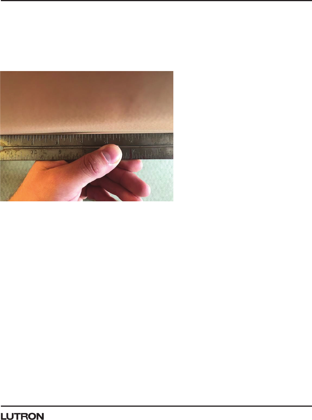
Wall Inspection and Preparation
One of the most important factors to consider in any Palladiom installation should be the flatness of the wall selected.
A non-flat wall could be caused by various factors that include decorative wall coverings (tile, stone, etc.), plaster not
evenly applied, drywall spackle applied but not sanded evenly, etc. This non-flat wall could create a gap between
the adapter and wall or the faceplate and adapter. If the gap is too large, the snaps in one or more corners may
disengage which will cause rocking, or in some extreme cases the unit will not be able to be installed into the adapter
or may disengage over time.
Photo 2: Photo of straight edge used to evaluate wall flatness for Glass Units.

5 Customer Assistance — 1.844.LUTRON1
Application Note #705
Wall Inspection and Preparation (continued)
Additionally, the wall and the surrounding area in which the Palladiom unit is installed can impact Dynamic Backlight
Management (DBM). Based on your preference and the color of the wall, you may want to adjust the DBM settings in
your myRoom/HomeWorks Designer Tool. Shelves and other devices (to include additional Palladiom units) should be
installed at least 75 mm (3 in) from the bottom of the original keypad to the top of the shelf or other device.
Figure 3: Space required between bottom of keypad and shelf or unit directly below it.
75 mm
(3 in)
Floor
Shelf/Unit
Wall

6 www.lutron.com/support
Application Note #705
Wall Inspection and Preparation (continued)
Cutting Holes in Wall
If the installation wall is soft (ex. fabric, padded headboards), care should be taken to ensure the material does
not wrap around the Palladiom unit and block the dynamic backlighting sensor. If you wish to install a unit in this
environment, please contact Lutron Customer Assistance at 1.844.LUTRON1 for options.
Debris or burrs left from hole construction can cause gaps to exist between the wall and the Palladiom keypad.
Photo 3: Before and after photo of debris and burr created during drywall installations.
Gap

7 Customer Assistance — 1.844.LUTRON1
Application Note #705
Wallbox Installations
Prepare the wall and wallbox hole as described in the previous sections. Install the wallbox to ensure that the adapter
does not contact it and that the mounting bosses/brackets are as close to the wall as possible. The goal of this
installation is to ensure that the unit cannot shift on the wall under normal use while minimizing the gap between the
wall and the adapter.
If the screw mounting brackets/bosses are mounted behind the surrounding wall, use spacers to prevent adapter
warp. Cut the spacers to ensure the unit cannot shift on the wall (please use P/N 257453 on www.lutron.com). If the
installation causes the adapter to warp, the plastic and metal keypads may be easy to remove and glass keypads may
be difficult to remove.
For two-column keypads, a thicker adapter is provided. This adapter provides space for the wallbox flange and is
stiffer to help mitigate adapter warp.
Photo 4: Example of a protruding wallbox and its impact on the keypad.
Figure 4: Example of using a wallbox spacer to improve adapter installation.
Adapter

8 www.lutron.com/support
Application Note #705
EBB-1-3COL Installation Instructions
This product is only to be used for mounting a Palladiom 3-column keypad where a wallbox installation is preferred
over a surface-mount installation. EBB-1-3COL is for hollow wall or plaster installations. Do not use for concrete
pour installations.
142.7 mm
(5.6 in)
74.7 mm
(2.9 in)
Ø68 mm
(2.7 in)
40.6 mm
(1.6 in)
Wallbox Cutout Dimensions

9 Customer Assistance — 1.844.LUTRON1
Application Note #705
EBB-1-3COL Installation Instructions (continued)
1. Prepare opening per diagram on page 8. Two (2) holes (“A”) are provided to locate the Ø68 mm (2.7 in) hole saw cuts.
2. Secure wallbox to wall using included screws and clamps (“B”), or fasten to stud through the two (2) holes in the back
of the box (“A”).
Hollow Wall Installation
B
B
B
B
A
A
C
C
C
C
Photo 5: Highlighted layout for the hollow wall installation.
Photo 6: Highlighted layout for the plaster installation.
1. Prepare opening per diagram on page 8. Dry fit wallbox to check it fully seats in opening.
2. Fully seat four (4) mounting screws (“C”) used to fasten keypad adapter to wallbox. This ensures that the mounting
screws will be able to be used if plaster happens to get in these areas (“D”). Plaster is not intended to be placed in
these areas.
3. Apply plaster to the four (4) clamp screw areas (“E”), making sure that plaster gets in and around the screws. This is
what will hold the wallbox in the wall for a plaster install.
4. Insert plastered wallbox into opening.
Plaster Installation
D DE E
NOTE: Do not use for concrete pour installations. Wallbox is not rated for concrete pour installations.

10 www.lutron.com/support
Application Note #705
EBB-1-3COL Installation Instructions (continued)
Cable Retention Assembly
When required for local codes, use included cable tie to retain wires to wallbox. Below are instructions for proper
installation and use. Top and bottom Ø25 mm (0.98 in) knockouts are not compatible with this cable retention method.
Use Ø20 mm (0.79 in) knockouts if cable retention is required. It is recommended to install the cable tie prior to
installing the wallbox into a wall, and must be installed prior for plaster installations.
Step 1: Remove a Ø20 mm (0.79 in) knockout and insert cable tie through adjacent Ø20 mm (0.79 in) opening, which
does not need the knockout removed.
Insert cable tie (do not need to
remove knockout)
Remove
knockout
Step 2: Wrap cable tie around wallbox and connect both ends.
Photo 7: Visual instructions for step 1 of the cable retention assembly.
Wrap cable tie around
wallbox and connect
both ends
Photo 8: Visual instructions for step 2 of the cable retention assembly.

11 Customer Assistance — 1.844.LUTRON1
Application Note #705
Step 3: Pull wire into the wallbox and through the cable tie loop. Tighten securely.
Photo 9: Visual instructions for step 3 of the cable retention assembly.
EBB-1-3COL Installation Instructions (continued)
Cable Retention Assembly (continued)
Pull wire into wallbox and
through cable tie loop.
Tighten securely.

12 www.lutron.com/support
Application Note #705
Surface Mounting Installations
Palladiom was designed to accommodate installations where a wallbox does not exist or may not be desirable.
Prepare the wall and holes as described in previous sections. Space the backcover holes and screw locations
according to the installation schematics (figures 4 to figure 7). Additionally, the screw mounting locations are located
by specific features in the adapter (see photo 10 on page 14).
Figure 5: Installation for Palladiom one-column keypad surface mount installation.
Figure 6: Installation for Palladiom two-column keypad surface mount installation.
60 mm
(2.36 in)
30 mm
(1.19 in)
ø40 mm
(ø1.58 in)
Mounting
screws
ø53–65 mm
(ø2.1–2.6 in)
4x M2.9 pan
head screw
80 mm
(3.16 in)
40 mm
(1.58 in)
46 mm
(1.81 in)
23 mm
(0.91 in)
13 Customer Assistance — 1.844.LUTRON1
Application Note #705
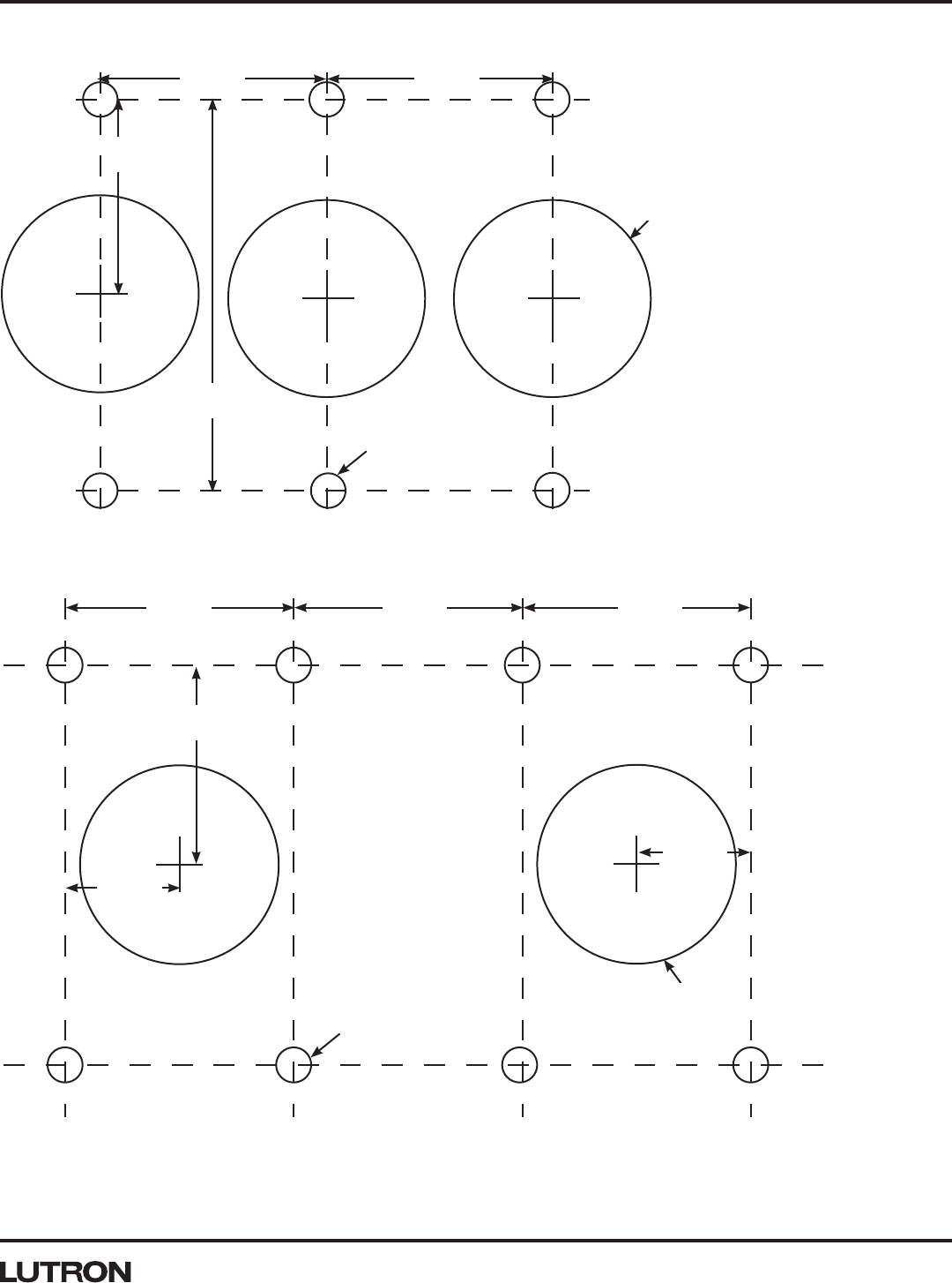
Surface Mounting Installations (continued)
Figure 7: Installation for Palladiom three-column keypad surface mount installation.
Figure 8: Installation for Palladiom four-column keypad surface mount installation.
40 mm
(1.58 in)
80 mm
(3.16 in)
ø40 mm
(ø1.58 in)
6x M2.9 pan
head screw
46 mm
(1.81 in)
46 mm
(1.81 in)
46 mm
(1.81 in)
46 mm
(1.81 in)
46 mm
(1.81 in)
40 mm
(1.58 in)
8x M2.9 pan
head screw
ø33-65 mm
(ø2.1-2.6 in)
23 mm
(0.90 in)
23 mm
(0.90 in)

14 www.lutron.com/support
Application Note #705
Surface Mounting Installations (continued)
Ganging or Pairing Palladiom with Other Devices
An installation recommendation is to place the adapter on the wall and level it to ensure it will be in the correct
orientation. Then mark the mounting locations on the wall (to establish positions for drywall anchors) or just install the
unit using an M2.9 screw (#4 Screw) with a screw head that does not interfere with the keypad. Then use the marked
mounting locations and the schematics on the previous pages to cut the holes for the backcover and QS wiring. If
during this installation, the screw or screwhead is too large, then it will interfere with backcover or the glass faceplate
snap and could prevent the faceplate from snapping to the adapter (see photo 10 for example).
Note that the photo below does NOT match the requirements listed above.
When installing the Palladiom keypad with other devices as well as additional keypads, Lutron recommends a
horizontal spacing of no less than 19 mm (3/4 in). Closer installation may produce noticeable product height
differences or mis-matching edge lines due to part tolerances as well as wallbox/unit installation inconsistencies.
Figure 9: Horizontal spacing recommended for keypad installations.
Photo 10: Example of improper screw used for surface mount installations.
19 mm
(0.75 in)

Application Note #705
15
Lutron Electronics Co., Inc.
7200 Suter Road
Coopersburg, PA 18036-1299 U.S.A.
02/2020 P/N 048705 Rev. B
Lutron Contact Numbers
Lutron, HomeWorks, myRoom, and Palladiom are trademarks or registered trademarks of Lutron Electronics Co., Inc. in the US and/
or other countries.
WORLD HEADQUARTERS
USA
Lutron Electronics Co., Inc.
7200 Suter Road
Coopersburg, PA 18036-1299
TEL: +1.610.282.3800
FAX: +1.610.282.1243
www.lutron.com/support
North & South America
Customer Assistance
USA, Canada, Caribbean:
1.844.LUTRON1 (1.844.588.7661)
Mexico:
+1.888.235.2910
Central/South America:
+1.610.282.6701
UK AND EUROPE:
Lutron EA Limited
125 Finsbury Pavement
4th floor, London EC2A 1NQ
United Kingdom
TEL: +44.(0)20.7702.0657
FAX: +44.(0)20.7480.6899
FREEPHONE (UK): 0800.282.107
Technical Support: +44.(0)20.7680.4481
ASIA:
Lutron GL Ltd.
390 Havelock Road
#07-04 King’s Centre
Singapore 169662
TEL: +65.6220.4666
FAX: +65.6220.4333
Technical Support: 800.120.4491
lutronsea@lutron.com
Asia Technical Hotlines
Northern China: 10.800.712.1536
Southern China: 10.800.120.1536
Hong Kong: 800.901.849
Indonesia: 001.803.011.3994
Japan: +81.3.5575.8411
Macau: 0800.401
Taiwan: 00.801.137.737
Thailand: 001.800.120.665853
Other Countries: +65.6220.4666
