
1601 J. P. Hennessy Drive, LaVergne, TN USA 37086 615/641-7533 800/688-6359 www.coatsgarage.com
HENNESSY
INDUSTRIES INC. Manufacturer of AMMCO
®
, COATS
®
and BADA
®
Automotive Service Equipment and Tools.
Manual Part No.: 941413 04
Revision: 6/18
4000SP
Drum & Disc
BRAKE LATHE
®
Installation Instructions
Operating Instructions
Safety Instructions
Maintenance Instructions
with Parts Identification
READ these instructions before placing unit in
service. KEEP these and other materials delivered
with the unit in a binder near the machine for
ease of reference by supervisors and operators.

ii • AMMCO 4000SP Brake Lathe

AMMCO 4000SP Brake Lathe • iii
Table of Contents
Safety Notices and Decals . . . . . . . . . . . . .iv
Warning
Cautions and Dangers . . . . . . . . . . . . . . . . . . . . . .iv
Owner’s Responsibility . . . . . . . . . . . . . . . . .v
Definitions of Hazard Levels . . . . . . . . . . . . .v
General Safety Instructions . . . . . . . . . . . . .vi
Before You Begin
Receiving . . . . . . . . . . . . . . . . . . . . . . . . . . . . . . . .1
Electrical Requirements . . . . . . . . . . . . . . . . . . . . .1
Installation . . . . . . . . . . . . . . . . . . . . . . . . . . . . . . .1
Preparation for Use . . . . . . . . . . . . . . . . . . . . . . . .2
Operating Specifications . . . . . . . . . . . . . . . . . . . .2
Principle Operating Parts . . . . . . . . . . . . . . . . . . . .3
Operating Instructions
Arbor Installation . . . . . . . . . . . . . . . . . . . . . . . . . .4
Adapters . . . . . . . . . . . . . . . . . . . . . . . . . . . . . . . .4
Basic Operation . . . . . . . . . . . . . . . . . . . . . . . . . . .4
Poly V-Belt Tension and Adjustment . . . . . . . . . . . .5
Basic Operation of Handwheels . . . . . . . . . . . . . .5
Reconditioning Brake Drums
Preparation . . . . . . . . . . . . . . . . . . . . . . . . . . . . . .5
Mounting Drums . . . . . . . . . . . . . . . . . . . . . . . . . .6
Reconditioning Disc Brake Rotors
Preparation . . . . . . . . . . . . . . . . . . . . . . . . . . . . . .8
Twin Cutter . . . . . . . . . . . . . . . . . . . . . . . . . . . . . .8
6950 Twin Cutter . . . . . . . . . . . . . . . . . . . . . . . . . .8
Rotor Mounting . . . . . . . . . . . . . . . . . . . . . . . . . . .9
Set Up and Reconditioning Rotors . . . . . . . . . . .10
Maintenance and Service
Oiling . . . . . . . . . . . . . . . . . . . . . . . . . . . . . . . . . .12
Cleaning . . . . . . . . . . . . . . . . . . . . . . . . . . . . . . . .12
Care of Arbors and Adapters . . . . . . . . . . . . . . . .12
Shear Gear Replacement . . . . . . . . . . . . . . . . . . .13
Parts Identification
Spindle . . . . . . . . . . . . . . . . . . . . . . . . . . . . . .14-15
Motor Mount and Drive Shaft . . . . . . . . . . . . .16-17
Crossfeed Assembly . . . . . . . . . . . . . . . . . . . .18-19
Disc Brake Feed Mechanism, #7751 . . . . . . .20-21
Drum Feed Gearbox Assy. 3037 . . . . . . . . . . .22-23
6950 Twin Cutter . . . . . . . . . . . . . . . . . . . . . . . . .24
Electrical Panel Assembly . . . . . . . . . . . . . . . . . .25
Contents

iv • AMMCO 4000SP Brake Lathe
Safety
Safety Notices and
Decals
For your safety, and the safety of others, read and
understand all of the safety notices and decals includ-
ed here and on the unit.
Read entire manual
before installing,
operating, or servic-
ing this equipment.
Proper maintenance
and inspection is
necessary for safe
operation.
Do not operate a
damaged lathe.
Warning
This equipment incorporates parts such as snap
switches and power receptacles which tend to pro-
duce arcs or sparks. Therefore, when located in a serv-
ice facility, the unit should be in a room or enclosure
provided for the purpose, or should be at least 18” or
more above floor to minimize the risk of igniting fuel
vapors.
Cautions and Dangers
1. Eye and face protection requirements:
“Protective eye and face equipment is required
to be used where there is a reasonable
probability of injury that can be prevented by use
of such equipment.” OSHA 1910.133 (a).
Protective goggles, safety glasses, or a face
shield must be provided by the purchaser/user
and worn by the operator of the equipment.
Make sure all eye and face safety precautions are
followed by the operator(s). Keep bystanders out
of the area.
2. Do not remove any safety equipment, belt
guards, or shortcut controls or operations.
3. Make sure drums and rotors are properly and
squarely mounted before starting lathe, and that
all parts are secure.
4. Do not wear loose clothing, jewelry, or gloves
when operating or working around a lathe.
5. Do not overload the lathe. Read and understand
the lathe specifications. Overloading is poor
machine tool practice, shortens the life of the
lathe, and could cause a failure resulting in
personal injury.
Failure to follow danger, warning, and cau-
tion instructions may lead to serious per-
sonal injury or death to operator or
bystander or damage to property. Do not
operate this machine until you read and
understand all the dangers, warnings and
cautions in this manual. For additional
copies of either, or further information,
contact:
Henne
ssy Industries, Inc.
1601 J.P. Hennessy Drive
LaVergne, TN 37086
(615) 641-7533 or (800) 688-6359
www.coatsgarage.com
WARNING

AMMCO 4000SP Brake Lathe • v
Owner’s Responsibility
To maintain machine and user safety, the responsi-
bility of the owner is to read and follow these instruc-
tions:
• Follow all installation instructions.
• Make sure installation conforms to all applicable
Local, State, and Federal Codes, Rules, and
Regulations; such as State and Federal OSHA
Regulations and Electrical Codes.
• Carefully check the unit for correct initial function.
• Read and follow the safety instructions. Keep
them readily available for machine operators.
• Make certain all operators are properly trained,
know how to safely and correctly operate the
unit, and are properly supervised.
• Allow unit operation only with all parts in place
and operating safely.
• Carefully inspect the unit on a regular basis and
perform all maintenance as required.
• Service and maintain the unit only with
authorized or approved replacement parts.
• Keep all instructions permanently with the unit
and all decals/labels/notices on the unit clean and
visible.
• Do not override safety features.
Definitions of Hazard
Levels
Identify the hazard levels used in this manual with
the following definitions and signal words:
DANGER
Watch for this symbol:
It Means: Immediate hazards, which will result in
severe personal injury or death.
WARNING
Watch for this symbol:
It Means: Hazards or unsafe practices, which could
result in severe personal injury or death.
CAUTION
Watch for this symbol:
It Means: Hazards or unsafe practices, which may
result in minor personal injury or product or property
damage.
Watch for this symbol! It means BE ALERT! Your
safety, or the safety of others, is involved!
CAUTION
WARNING
DANGER
Safety
1. Read and follow instructions.
2. Always wear eye protection, avoid loose
clothing and jewelry.
3. Keep all guards, shields, and covers in place and
in working order.
4. Keep bystanders out of work area.
5. Unplug unit from power source before servicing
or adjusting.
6. Maintain unit properly, keep work surfaces and
work area clean.
CAUTION
Prevent accidents and injury, read and follow instructions.

vi • AMMCO 4000SP Brake Lathe
Safety
1. Keep guards in place and in working order.
2. Remove adjusting keys and wrenches from the
tool before turning it on. Make this a habit.
3. Keep work area clean. Cluttered areas and
benches invite accidents.
4. Avoid dangerous operating environments. Do not
use power tools in areas where explosive vapors
are present or in damp or wet locations. Do not
expose them to rain. Keep the work area clean
and well lighted.
5. Keep children away. All bystanders should be
kept completely away from the work area.
6. Make the workshop kid-proof. Use padlocks and
master switches, and remove starter keys.
7. Don’t force a tool. It will do the job better and
safer at the rate for which it was designed.
8. Use the right tool. Don’t force a tool or an
attachment to do a job for which it was not
designed.
9. Dress properly. Loose clothing, gloves, neckties,
shop rags or jewelry may get caught in moving
parts. Non-slip footwear is recommended. Wear
protective hair covering to contain long hair.
10. Wear eye protection. Safety glasses, goggles, or
a face shield will help protect the operator from
injury. Use a face shield and dust mask during
dusty operations.
11. Secure the work properly to the unit for setup
and tool bit positioning. Do not attempt to hold a
drum or rotor steady on the arbor with your
hands. Both hands must be free to operate unit.
12. Don’t overreach. Keep proper footing and balance
at all times when lathe is in operation or when
working around the unit.
13. Maintain tools with care. Keep tools sharp and
clean for best and safest performance. Follow
instructions for lubricating and changing
accessories.
14. Remove power from the unit and disconnect
tools before servicing and when changing
accessories such as blades, bits, cutters, etc.
Follow lockout and tag-out procedures as
required.
15. Avoid unintentional starting. Make sure the
switch is in the OFF (O) position before plugging
the machine in or performing any maintenance or
service work.
16. Use recommended accessories. Consult the
manufacturer’s catalogs for recommended
accessories. Use of improper accessories may
cause risk of injury to operator or bystanders.
17. Never stand or lean on a lathe. Serious injury
could occur if the lathe is tipped or if the cutting
tool is unintentionally contacted.
18. Check damaged parts carefully. Before further
use of the lathe, a guard or other part that is
damaged should be carefully checked.
Immediately replace all damaged, missing, or
non-functional parts. Check for alignment of
moving parts, binding of moving parts, breakage
of parts, mounting, and any other conditions that
may affect operation. Guards and other parts that
are damaged should be properly repaired or
replaced before lathe is used again.
19. Always feed the work into a blade or cutter and
against the direction of rotation. Cutters and tool
bits are designed to cut from the inside of a drum
or rotor to the outer edge. Do not attempt to cut
from the outside edge in to the center.
20. Never leave tools running unattended. Turn the
power off. Don’t leave the tool until it comes to a
complete stop.
21. Never use compressed air to blow the tool clean.
Chips and dust may be driven between machined
parts and into bearings, causing undue wear.
They may also contact persons in the area
causing personal injury.
22. Operate the lathe in the proper environment. The
lathe incorporates parts such as snap switches
and power receptacles, which tend to produce
arcs or sparks. Therefore, when located in a
garage the unit should be in a room or enclosure
provided for the purpose, or should be at least
18” or more above the floor to minimize the risk
of igniting fuel vapors.
General Safety Instructions
Before operating the lathe, review the warning information on the lathe and the cautions, warnings and dangers
in this manual. Also review the following general safety instructions. Failure to follow safety instructions could
result in personal injury to operator or bystanders and damage to the lathe or personal property.

Before You Begin
Receiving
The shipment should be thoroughly inspected as soon as it is
received. The signed bill of lading is acknowledgement by the
carrier of receipt in good condition of shipment covered by our
invoice.
If any of the goods called for on this bill of lading are shorted
or damaged, do not accept them until the carrier makes a nota-
tion on the freight bill of the shorted or damaged goods. Do this
for your own protection.
NOTIFY THE CARRIER AT ONCE if any hidden loss or damage
is discovered after receipt and request the carrier to make an
inspection. If the carrier will not do so, prepare a signed state-
ment to the effect that you have notified the carrier (on a spe-
cific date) and that the carrier has failed to comply with your
request.
IT IS DIFFICULT TO COLLECT FOR LOSS OR DAMAGE AFTER
YOU HAVE GIVEN THE CARRIER A CLEAR RECEIPT.
File your claim with the carrier promptly. Support your claim
with copies of the bill of lading, freight bill, invoice, and photo-
graphs, if available.
Although AMMCO’s responsibility ceases upon delivery of the
shipment to the carrier, we will gladly assist in tracing lost ship-
ments. Our willingness to assist in every possible manner does
not make AMMCO responsible for collection of claims or
replacement of lost or damaged materials. Shipping damage
claims will not be handled under warranty.
Installation
1. Assemble bench according to the instructions provided.
Tighten all fasteners securely.
2. After assembly, the bench should be leveled and may be
bolted down with 3⁄8 or 7⁄16 inch bolts or lag screws.
3. Unbolt the lathe from the shipping pallet. Lift the lathe onto
the bench.
4. Bolt the lathe to the bench with the hardware provided.
Tighten fasteners securely.
5. Remove any packing materials and protective wrapping
from the lathe and components.
6. Make sure lathe is turned off. Plug lathe into a properly
installed and grounded outlet that matches the lathe plug.
7. Remove the shipping plug, insert the oil dipstick, and check
oil level. The lathe is shipped with the correct amount and type
of oil. Add oil as necessary to reach the correct mark on the dip-
stick. Use only EP-80-90 gear oil. Oil level should be checked
often. See figure 2.
8. Clear the area and turn lathe on. Check for proper operation
(motor and spindle rotation).
AMMCO 4000SP Brake Lathe • 1
Figure 1 - Power cord plug and receptacle types
Figure 2 - Check oil level
Electrical Requirements
The lathe must be properly grounded to pro-
tect the operator from shock. The lathe is
equipped with an approved 3-conductor cord
and a 3-prong grounding type plug to fit the
proper grounding-type receptacle. Should an
extension cord be required, use 3-conductor
cords with 3-prong grounding plug and 3-
prong grounding receptacle properly rated to
handle this electrical power tool only. Do not
modify a cord or plug to match a receptacle;
have a qualified electrician install an appropri-
ate outlet to match the lathe requirements.
Repair or replace any worn or damaged power
cords immediately.
Verify that the lathe plug and grounding-type
receptacle match as shown in Figure 1.
115 VAC
220 VAC

2 • AMMCO 4000SP Brake Lathe
Operating Specifications 4000
Overall Lathe Height . . . . . . . . . . . . . . . . . . . .17.25” (438 mm)
Lathe Shipping Weight . . . . . . . . . . . . . . . . . .385 lbs. (175 kg)
Floor Space Requirements - Width . . . . . . .48” (1219.20 mm)
Floor Space Requirements - Depth . . . . . . .34.5” (901.70 mm)
Spindle to Floor . . . . . . . . . . . . . . . . . . . . .39.375” (1000 mm)
(mounted on optional bench)
Electrical requirements
Standard: 115 VAC, 60 Hz, single-phase, fused at 20 amps
Optional: 220 VAC, 60 Hz, single-phase, fused at 15 amps
Spindle Motor . . . . . . . . . . . . . . . . . .1 HP, 60 Hz, 115/220 VAC
Spindle Travel . . . . . . . . . . . . . . . . . . . . . . . . .6.875” (175 mm)
Spindle Speed . . . . . . . . . . . . . . . . . . . . . . . . . . . . . .100 RPM
Spindle Feed Speed-Drum . . . . . . . . . . . . . . . . . . .0.005 in/rev
Cross Feed Speed-Rotor . . . . . . . . . . . . . . . . . . . .0.002 in/rev
Handwheel Graduations . . . . . . . . . .0.002 inches (0.050 mm)
Maximum Rotor Diameter* . . . . . . . . .14.5 inches (368.3 mm)
Maximum Rotor Thickness . . . . . . . . .1.875 inches (47.63 mm)
Brake Drum Diameter
Minimum: 6 inches
Maximum: 28 inches
Maximum drum depth . . . . . . . . . . . . . . . . . .6.875” (175 mm)
Maximum load
Standard: 1” Arbor . . . . . . . . . . . . . . . .100 lbs. (45.36 kg)
Optional: 1.875” Arbor . . . . . . . . . . . . .200 lbs. (90.72 kg)
* The optional No. 6936 Cross Feed Extension increases the
maximum rotor diameter to 19 inches (483 mm).
Preparation for Use
1. Inspect all adapters and accessories for
burrs, nicks, or other damage.
2. Clean accessories with a vaporizing solvent.
3. Apply a light film of oil to all adapters to pro-
tect their machined surfaces from rust. Refer to
the maintenance section for more information.
There is a circuit breaker located on the
electrical panel to prevent damage to
the lathe in the event the motor is
overloaded. Move the switch to the off
position and correct overloading situa-
tion before re-setting circuit breaker.
Serious personal injury could result if
circuit breaker is re-set while lathe is
still on.
WARNING

AMMCO 4000SP Brake Lathe • 3
Work Light
1” Arbor
Shield
Twin Cutter
Boring Bar and
Boring Bar Clamp
Cross Feed Lock
Cross Feed
Handwheel
Power Cord
Spindle Feed Handwheel
Spindle Feed
Engaging Lever
Spindle Lock
Oil Dipstick
Grease Fitting
Cross Feed
Engaging Lever
Cross Feed
Gearbox
V-Belt
Adjusting Lever
Belt Tension
Adjusting Nut
ON/OFF Switch
Draw Bar
Drive Motor
Pulley Guard
Principle Operating Parts

Operating Instructions
Arbor Installation
The 1” arbor shipped with the lathe has been carefully
matched to the lathe during final assembly and testing. Witness
marks have been etched onto the arbor and the spindle for pre-
cise, repeatable alignment.
The witness marks must be carefully aligned when installing
the arbor (Figure 3). A true-running arbor is essential to profes-
sional quality brake drum and rotor reconditioning.
1. Locate the witness marks on the arbor and the spindle.
2. Insert the arbor into the spindle making sure the witness
marks are aligned.
3. Tighten the drawbar (located at the rear of the spindle) to
pull the hardened and ground tapers of the arbor into the match-
ing seats in the spindle.
Adapters
Although the adapters, arbor, and spindle are made
of top grade steel and are turned, hardened, and pre-
cision ground to close tolerances, great care should
be taken in their use, handling, and storage. Even
the smallest nick, scratch, or loose chip on the
machined mating surfaces can cause incorrect rotor
mounting alignment. This will cause inaccurate
machining.
Always inspect the surface, face, and seating tapers of each
part before use (figure 4). Wipe each part clean before and after
using it. Carefully correct any flaw with a fine stone. If damage
cannot be corrected, replace the part.
Basic Operation
To completely understand drum and rotor turning you must
have knowledge of the lathe itself.
Spindle — The spindle is a motor driven shaft that turns the
arbor upon which the brake drum or rotor is mounted. By turn-
ing the drum and holding a cutting tool against the inner braking
surface, metal can be removed.
Do not try to move any feed levers or dials without
the drive motor running. Damage may occur to the
gear trains.
Spindle Feed — By operating the spindle feed lever, the spin-
dle will move the mounted brake drum to the left. This feeds the
braking surface across the cutting tool as the drum moves away
from the tool. Spindle feed may also be done manually using the
spindle feed handwheel.
CAUTION
CAUTION
4 • AMMCO 4000SP Brake Lathe
Figure 3 - Align witness marks during arbor
installation
Figure 4 - Use care to avoid damaging mating
surfaces
Arbor
Keep the arbor tapers and seats clean
Witness Marks
Typical Inner & Outer Adapters
Seating Tapers
Machined Surfaces

Figure 5 - Engage lever and loosen nut
Figure 6 - Clockwise rotation of handwheels
Figure 7 - Counterclockwise rotation of handwheels
Figure 8 - Measure drum diameter
Spindle feed refers to the distance the spindle is pulled per
revolution.
Spindle Speed — Spindle speed is measured in RPM’s. Refer
to the specifications listed on page 2 for the RPM rating.
Cross Feed — The cross feed draws the tool bit across the
face of a brake rotor or flywheel when the cross feed drive is
engaged. The cross feed may also be operated manually using
the cross feed handwheel.
Feed Speed — Feed speed refers to the thousands of an inch
the cutting tools move per revolution of the spindle.
Poly V-Belt Tension and Adjustment
A loose belt can cause slippage when taking heavy cuts. A belt
that is too tight can cause vibration and possible sub-standard
finishes on machined drums and rotors. Check and adjust belt
monthly.
1. Position the poly v-belt speed-adjusting lever to the left
(counterclockwise) to the fully engaged position.
2. Loosen the adjustment nut. See figure 5.
3. The poly v-belt should be adjusted to deflect 3/32” with a
5-pound push on the belt. The ideal tension is the lowest tension
at which the belt will not slip under the highest load.
4. Retighten the adjusting nut.
Check and adjust as required the tension during the first day of
operation. Do not overtighten.
Basic Operation of Handwheels
Clockwise rotation of the spindle feed handwheel retracts the
spindle in towards the lathe.
Clockwise rotation of the cross feed handwheel moves the
cutting tool in towards the lathe. Refer to figure 6.
Counterclockwise rotation of the spindle feed handwheel
extends the spindle out away from the lathe.
Counterclockwise rotation of the cross feed handwheel moves
the cutting tool out away from the lathe. Refer to figure 7.
Reconditioning Brake Drums
Preparation
1. Measure the diameter of the brake drum with a brake drum
micrometer (figure 8).
2. Determine if the drum will be within maximum rebore lim-
its after reconditioning.
NOTE: Most often, the DISCARD diameter is cast into the
brake drum, not the maximum machining diameter.
3. Inspect brake drum. Do not attempt to machine a drum that
is damaged or in poor condition.
AMMCO 4000SP Brake Lathe • 5
Poly V-belt
Adjustment Nut
Belt Adjusting Lever
Spindle Feed
Handwheel
Cross Feed
Handwheel
Spindle rotates when
motor is turned on.
Spindle Feed
Handwheel
Cross Feed
Handwheel

A
C
B
L
K
D
F
Hubbed Brake Drums
Hubbed Brake Drums — Tapered cone adapters fit
in the bearing seats, making contact near the middle
of the bearing race whenever possible rather than near
an edge. Various adapters and spacers may be used to
fill out the shaft of the arbor.
Hubless Brake Drums — A cone fits into the center
hole of the drum from the inside to center the drum on
the arbor. Select a hubless adapter which will fit inside
the drum, against the flat lug hole surface and either
straddle the boltholes to avoid mounting against a burr,
or remove the burrs. Slip the hubless adapter onto the
arbor followed by a spring, the cone, the drum, and
another hubless adapter. Fill out the shaft with spacers
as needed.
Key to Mounting Adapters, Cones, and Related Parts
A. 1” Arbor
B. Flange Plate
C. Spring
D. Centering Cone
E. Rotor, Drum or Flywheel
F. Flange Plate
G. Spacer(s)
H. Self-Aligning Spacer (AMMCO)
I. Arbor Nut
Note: The self-aligning spacer should always be used
next to the arbor nut when tightening. To avoid over-
tightening, wrench tighten the arbor nut counterclock-
wise until the drum and adapters begin to turn on the
arbor, then continue to advance the wrench 1/16 of a
turn. DO NOT overtighten the arbor nut.
Mounting Drums
1. Loosen the boring bar clamp nut and push the boring bar all
the way into the clamp.
2. Mount the drum on the arbor using the proper adapters,
cones, and spacers. Use examples in Figure 10 for guidance.
3. Wrap the drum silencer band snugly around the drum. Be
sure it covers up to the right-hand edge (figure 9).
IMPORTANT: The spindle feed handwheel will not operate
unless the spindle feed engagement lever is in the OFF posi-
tion. Feed should only be adjusted when the spindle is turning.
4. Position the cross slide and spindle by turning their respec-
tive handwheels to their maximum clockwise (in) position. Then
back off the cross feed handwheel 2 complete turns and the
spindle handwheel 4 complete turns.
6 • AMMCO 4000SP Brake Lathe
Figure 9 - Attach silencer band
Figure 10 - Typical drum mounting configurations
Buckle Finger
Silencer Band for Drums
A
C
B
E
H
D
F
I
G
Hubless Brake Drums

Figure 12 - First scratch cut
Figure 11 - Positioning the boring bar
Figure 13 - Set drum diameter measurement
Figure 14 - Second scratch cut
5. Position the boring bar by loosening the boring bar clamp
nut and sliding the boring bar inward toward the drum until the
tool bit is close to the drum (figure 11).
The boring bar position is changed whenever a drum of differ-
ent diameter is machined.
The entire boring bar clamp may also be swiveled to achieve
the best cutting position.
6. Turn the drum by hand to make sure that everything is clear.
7. Turn the lathe ON.
8. Advance the tool bit manually until it just contacts the drum
surface momentarily and makes a scratch cut (figure 12).
9. Loosen the dial lock screw on the cross feed handwheel
and set the dial to the diameter of the drum as measured with
the micrometer (figure 13). Tighten the lock screw.
This setting will be the reference used to help determine the
drum recondition diameter.
10. Back the tool bit off and turn the lathe OFF.
11. Loosen the arbor nut, rotate the drum 1⁄2 turn (180°) on
the arbor and inner adapter, and retighten the nut.
12. Turn the lathe ON.
13. Turn the spindle feed handwheel 1⁄2 turn in either direc-
tion and make a second scratch cut (figure 14).
14. Turn the lathe OFF.
15. Examine the scratch cuts.
If the first and second cuts are opposite one another (180°
apart), remove the drum from the arbor, check the mounting
adapters and arbor for nicks, burrs, or chips, remount the drum,
and repeat scratch cut process.
If the scratches are side by side, proceed to step 16.
16. Turn the spindle feed handwheel until the deepest worn
groove of the drum lines up with the point of the tool bit.
17. Advance the tool bit into the bottom of the groove by
rotating the cross feed handwheel counterclockwise.
NOTE: These operations may be done with the lathe running.
The depth of cut dial will show the approximate reconditioned
diameter of the drum. This measurement must be compared
with:
A. The maximum rebore limits cast into the drum.
B. The measured diameter to determine the best amount
of material to be removed in one pass.
18. Determine the depth-of-cut by these general guidelines:
• Roughing cuts should be no deeper than 0.020”.
• Finish cuts should be no shallower than 0.004” deep.
AMMCO 4000SP Brake Lathe • 7
First
Scratch
Cut
Dial Lock
Screw
Second
Scratch
Cut

19. With the lathe running, set the depth-of-cut dial to the
depth desired and lock the cross feed by tightening the lock
knob (figure 15).
20. Set the feed shut-off by sliding it on the shaft to a point
that approximately equals the depth of the drum and tightening
it in place (figure 16). The feed will stop when it reaches this
point.
21. Engage the feed lever to begin drum reconditioning.
Reconditioning Disc Brake
Rotors
Preparation
1. Inspect the rotor carefully for scoring, rust ridges (at the
inner and outer circumference of the rotor), and hard spots. Any
excessive wear or deformity should be noted and, if not within
acceptable limits, the rotor should be replaced.
2. Use a micrometer to check the thickness of the rotor (fig-
ure 17) at no less than 3 points around the circumference about
1” (2.54 mm) in from the outer diameter.
If the rotor thickness varies between readings, it should be
reconditioned. However, if the thickness is less than the mini-
mum established by the manufacturer, or if it will be less after
reconditioning, the rotor should be replaced.
NOTE: Most often the DISCARD thickness dimension is cast
or stamped into the rotor, not the minimum machine-to thick-
ness.
Twin Cutter
A twin cutter tool is used to recondition both surfaces of a
brake rotor at the same time. The twin cutter replaces the bor-
ing bar on top of the cross feed after removing the upper and
lower tool bar clamps.
Model 6950 Twin Cutter
1. Mount the twin cutter on the cross feed with the stud bolt
extending through the cast slot (see figure 18). The slot helps
center the twin cutter to the rotor.
2. Secure the twin cutter to the cross feed with self-aligning
nut and washer assembly. Tighten the nut firmly.
8 • AMMCO 4000SP Brake Lathe
Figure 15 - Lock cross feed
Figure 16 - Set spindle feed shut-off
Figure 17 - Measure rotor thickness
Figure 18 - Install the twin cutter
Cross Feed Lock Knob
Feed shut-off
Spindle feed lever
Upper and lower boring
bar clamps
Cross slide self-aligning nut/washer
Twin
cutter
Cross slide self-aligning
nut/washer

AMMCO 4000SP Brake Lathe • 9
Rotor Mounting
Review the descriptions of mounting a brake drum
on page 6. The same directions apply when mounting
a brake rotor. Hubbed rotors are mounted on adapters
that fit into the bearing races. Hubless rotors use a
cone in the center hole and a hubless adapter on each
side of the rotor. Spacers are used to fill out the arbor
shaft so that the arbor nut can be tightened. The
setups illustrated in Figure 19 are typical of the many
mounting configurations necessary to meet the
requirements of brake rotor reconditioning. The
adapters, cones, and spacers supplied with the lathe
will allow reconditioning of the majority of the rotors
found on current production vehicles. Optional
adapters, cones, and spacers are available to meet
special needs.
NOTE: Adapters may also be used as spacers to fill
out the arbor shaft if care is taken to prevent damage
to their machined surfaces.
The patented self-aligning spacer prevents diagonal
thrust on the adapters. The self-aligning spacer should
always be used adjacent to the arbor nut.
- 1" Arbor
- Arbor Nut
- Self-Aligning Spacer
- Spacer
- Spring
- Flange Plate
- Flange Plate
- Centering Cone
- Small Double Taper Adapter
- Large Double Taper Adapter
- Adapter, Used as Spacer
Figure 19 - Typical rotor mounting configurations

Set Up and Reconditioning Rotors
1. Install a silencer band on the mounted rotor. Stretch the band
around the rotor and hook the metal loop over a lead weight. Refer
to figure 20.
2. Center the twin cutter to the rotor (figure 21). Loosen the stud
nut and adjust the twin cutter so that the rotor is centered between
the tool bits. The slot of the twin cutter should be approximately
parallel to the lathe spindle. Tighten the stud nut firmly.
3. Install the safety shield as shown in figure 22. Review the cau-
tions and dangers section and the general safety information at the
beginning of this manual. The safety shield is easily screwed onto
the twin cutter in the threaded mounting hole provided.
Always wear safety glasses or a face shield. Cutting or
grinding on an exposed surface such as a rotor will pro-
duce flying chips and debris.
4. Attach the optional 7075 Pad Silencer and the Clip-on Silencer
as needed for composite rotors.
5. Make sure that the tool bits clear the rotor surfaces and the
silencer band. Give the rotor a full turn by hand and watch for clear-
ance all the way around.
6. Turn the lathe ON.
7. Turn each tool bit control (the outer knurled knobs, figure 23)
clockwise until the tool bits just contact the rotor surfaces.
8. When the tool bits make contact, rotate each of the inner
depth-of-cut collars to zero and back the tool bits away from the
rotor.
From this point on, all tool adjustments will be made with the tool
bit controls. Then inner depth-of-cut collars will be the reference
and should not be moved.
9. Turn the cross feed handwheel until the tool bits are at mid-
point of the rotor face.
WARNING
Figure 20 - Attach silencer band
Figure 21 - Center the twin cutter
Figure 22 - Attach the safety shield
Figure 23 - Tool bit controls
10 • AMMCO 4000SP Brake Lathe
Silencer band
Twin cutter
Stud nut
Tool bits
Safety shield
Twin cutter
Inner depth-
of-cut collars
Tool bit controls
Hold knob with one
hand – turn collar
Each increment =
0.002” english,
0.05 mm metric

Figure 24 - First scratch cut
10. Turn the left-hand tool bit control until the tool bit contacts
the rotor surface and makes a scratch cut (figure 24). After the cut
is made, back the tool bits off and turn the lathe OFF.
The scratch will usually appear as an incomplete circle. This is
caused by runout or wobble due to rotor condition, or by the way
the rotor is mounted on the arbor (figure 25).
11. Check rotor mounting by loosening the arbor nut and turning
the rotor 180° by hand on the arbor. Make sure the inside adapter
does not rotate along with the rotor. Then retighten the arbor nut,
turn the cross feed handwheel back 1/2 turn, turn the lathe ON, and
repeat step 10 to make a second scratch cut (figure 26).
12. If the scratch cuts are side-by-side, the runout or wobble is
caused by rotor condition. A dial indicator may be used to compare
rotor runout with manufacturer’s specifications. See figure 27.
13. If the scratch cuts are opposite one another (180°), the rotor
may not be properly mounted on the arbor. Remove the rotor and
examine the arbor and all adapters for nicks, burrs, chips, dirt, or
rust. Inspect the rotor hub for loose or damaged bearing cups.
Clean, repair, remount, or replace as necessary.
14. Recheck the setting of the depth-of-cut collars, which were
set to zero earlier by moving the tool bits inward until they just con-
tact the surfaces of the rotor. The collars should be at zero. Reset
the collars if necessary.
15. Turn the cross feed handwheel clockwise until the tool bits
are near the rotor hub.
16. Turn the lathe ON.
17. Turn both tool bit controls to the desired depth-of-cut and lock
them in position by tightening the red lock knobs above the tool
bits.
18. Engage the automatic cross feed (figure 28) by moving the
lever to the rear of the lathe. The cross feed will stop automatically
when the cutting tools have moved all the way across the face of
the rotor.
19. Exert light pressure inward on cross feed while turning cross
feed handwheel slowly clockwise until the leadscrew is engaged.
AMMCO 4000SP Brake Lathe • 11
Figure 25 - Rotate rotor 180°
Figure 26 - Second scratch cut
Figure 27 - Using a dial indicator
Figure 28 - Engage automatic
cross feed
First scratch cut
Rotate rotor only 180°
Loosen arbor
nut, do not turn
inside adapter
Second
scratch cut
Scratch cuts
opposite each
other
Dial indicator
ON
OFF

Double Chuck Adapter
Mounting drums or rotors using the Ammco double
chuck adapter.
Figure 6 – Double Chuck Adapter
1. Thoroughly clean the surface of the rotor or drum
that will be mounted on the double chuck.
2. Place the hubless rotor or drum on a flat clean sur-
face. Install the double chuck by positioning the appro-
priate jaws in the center hole. Tighten the jaws by
inserting the key into one of the key slots in the side of
the chuck turning counterclockwise. The double chuck
will automatically self center the rotor or drum.
Note: Make sure that the chuck jaws are tight.
Do not leave the key in the key slot when
starting the brake lathe.
3. Install the backing plate onto the brake lathe arbor
with offset facing outward.
4. Ins all the double chuck, with rotor or drum
installed, onto the 1-inch arbor. Use the spacers sup-
plied with the brake lathe so that it extends out to the
arbor threads.
5. Use the arbor nut supplied with the machine and
tighten the nut against the spacers.
6. After tightening the double chuck, turn on the
brake lathe to check for runout of the rotor or brake
drum. Machine the rotor or drum.
Note: Always use the backing plate to help eliminate
rotor or drum vibration during turning. If necessary, use
a small spacer before the installation of the backing
plate.
CAUTION
12 • AMMCO 4000SP Brake Lathe

Maintenance and Service
Oiling
The lathe is shipped from the factory with the correct amount
and type of oil. Check oil level frequently as shown in figure 29,
and refill as necessary with EP-80-90 gear oil.
After every 500 hours of use, drain the oil and refill to the
appropriate level on the dipstick with clean EP-80-90 gear oil.
Use the oil drain plug on the front of the lathe to drain the old
oil. See figure 30.
The drum feed gearbox and the disc brake feed mechanism
assemblies are filled with a special lubricant and need no further
internal lubrication.
Lubricate the cross feed once each month with automotive
chassis grease. Pump the grease into the fitting until clean
grease comes out the relief slot at the base of the fitting as
shown in figure 31.
Use a hand pump grease gun only. A high-pressure gun can
burst the lathe casting.
Grease the lead screw drive monthly (figure 32). Locate the
lead screw drive by pulling the protective boot back.
Oil exposed metal parts periodically to prevent rust.
Cleaning
Keep the lathe as clean as possible for trouble-free operation,
as well as safety and longer lathe life. Use a brush to sweep
metal chips and dust off the lathe.
Do not use compressed air to blow the lathe clean. Chips and
dust may be driven between machined parts and into bearings,
causing undue wear.
Care of Arbors and Adapters
Although the adapters, arbors, and spindle are made of top
grade steel and are turned, hardened, and precision ground to
close tolerances, great care should be taken in their use, han-
dling, and storage. Even the smallest nick, scratch, or loose chip
can cause incorrect rotor or drum alignment, resulting in inac-
curate reconditioning.
Remove all adapters from the arbor after reconditioning a drum
or rotor and wipe them clean - especially the inboard adapter.
When a finished drum or rotor is removed from the arbor, the
inboard adapter may move slightly away from the face of the
arbor and allow metal chips to fall into the opening, causing a
poor mounting for the next drum or rotor.
Regularly inspect the faces and seating tapers of the adapters
for nicks and scratches, correct any flaw with a fine stone. If the
damage cannot be corrected, replace the adapter. Handle the
adapters and arbors with care and store them on individual
hooks. Do not throw them into a box. The adapters are designed
for mounting drums and rotors only. Do not misuse the
adapters.
Figure 29 - Oiling
Figure 30 - Drain plug location
Figure 31 - Cross feed grease fitting
Figure 32 - Lead screw drive
Grease fitting
for cross feed
Dipstick
Oil level
Oil drain plug
Relief slot
Feed mechanism lead screw
AMMCO 4000SP Brake Lathe • 13

Shear Gear Replacement
The shear gear is located in the drive housing under the dot
plug cover. It is designed to “strip out” and prevent gearbox
damage should a tool accidentally jam.
Remove the dot plug button. Remove the C-clip. Remove the
shear gear. Remove any stripped teeth from the drive housing.
Install the new gear. The concave side of the C-clip faces the
gear to maintain pressure. Replace the dot plug button.
Parts Identification
The following pages illustrate and identify the component
parts of the 4000 lathe. Complete parts breakdowns with
exploded view illustrations are provided to facilitate the ordering
of spare or replacement parts. Assemblies are outlined where it
is recommended the individual parts not be ordered separately.
These assemblies are furnished because some parts are
staked, pinned, or press fitted, then drilled, machined, or bored.
Accuracy must be maintained.
14 • AMMCO 4000SP Brake Lathe

AMMCO 4000SP Brake Lathe • 15

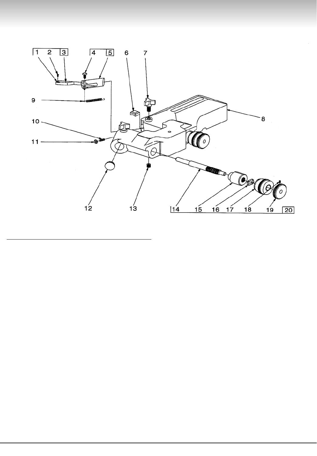
Spindle
PART
ITEM NO. Qty. DESCRIPTION
1 903102 1 Nut, arbor
2 903101 1 Arbor
3 903159 1 Ring, retaining
4 923682 1 Ring, adapter
5 903085 2 Boot
6 940720 1 Seal, oil, double-lip
7 903089 2 Ring, oil seal adapter
8 903164 1 Seal, oil
9 903033 2 Washer, thrust
10 903153 1 Spindle body, 3000/4000
11 909831 1 Key, drive
12 906486 1 Screw, cup point set
14 909830 1 Quill, drive, 3000/4000
15 900283 1 Washer, lock, 3000/4000
16 901602 1 Screw, hex hd. cap, 3000/4000
17 910216 1 Quill, drive, 4100/7700
18 906868 1 Screw, flat hd., 4100/7700
19 910737 1 Block, keyway, 4100/7700
20 903032 * Shim (0.005 THK)
921322 * Shim (0.0075 THK)
21 904670 1 Nut, lead screw, 4000/7000
22 907344R 1 Rear flange assembly, 4000
23 900209 4 Screw, skt. hd. cap, 4000, 4100
24 904671 1 Nut, take up
25 903338 1 Screw, skt. hd. set
26 904435 1 Ring, boot, 4000/4100
27 909592 1 Clamp, front
28 903142 1 Plug, brass
29 906854 1 Knob
30 903319 2 Screw, skt. hd. cap, 4000
31 909645 1 Rod, lock, 4000
32 909998 1 Clamp, rear, lower
33 909999 1 Clamp, rear, upper
34 906825 2 Screw, skt. hd. cap
35 900213 1 Screw, set
36 907005 1 Drawbar & nut assy, 3000/4000
37 903086 1 Boot & spring, 3000/4000
38 903037 1 Feed mechanism, 4000
16 • AMMCO 4000SP Brake Lathe

AMMCO 4000SP Brake Lathe • 17

Motor Mount and Drive Shaft
PART
ITEM NO. Qty. DESCRIPTION
1 906766 1 O-ring
2 906101 2 Screw, hex hd. cap
3 921557 2 Washer, lock
4 902165 1
Motor/bracket assembly
115/230V,
60Hz, 1Ph
6 940538 1
Pulley, drive, 4000SP
7 900220 2 Set screw, 3000/4000
8 903023 1 Shaft, motor mount
9 903015 1 Lever, belt tension
10 903035 1 Pin, eccentric belt release
11 907348 1 Lever belt release assembly
12 903088 1 Handle, belt release
13 900320 1 Knob, ball
14 903180 1 Screw, socket hd.
15 902364 * Washer, wave
16 903223 1 Bushing, motor mount shaft
17 903377 1 Nut, hex
18 903166 1 Plug, Welch
19 903172 1 Ring, retaining I.D.
20 903394 2 Cup, bearing
21 903393 2 Bearing, Cone
22 903372 1 Plug, allen pipe
23 922006 1 Fitting, grease
24 909847-C 1 Shaft, worm w/square key
PART
ITEM NO. Qty. DESCRIPTION
25 903169 * Shim, 0.005”
(*Quantity as required)
903170 * Shim, 0.007”
(*Quantity as required)
903171 * Shim, 0.020”
(*Quantity as required)
26 903186 1 Cap and seal assembly
27 903010 1 Cap, bearing seal
28 903163 1 Seal, oil
29 940581 1
Pulley w/pin and tube, 4000SP
30 924239 1 Pin, groove, 4000/4100
31 925588 1 Tube, rubber, 4000/4100
32 940141 1 Poly V-belt
33 900236 1 Screw, hex hd. cap
34 940139 1 Key, square
35 903215 1 Sleeve, oil filler
36 903148 1 Dipstick
37
8301035
1 Nut, self-locking
39 907788 1 Guard, belt
40 910352 1 Panel assembly, electrical
41 900220 2 Screw, set
42 925454 1 Key, square
921743
1
Motor/bracket assembly
230V, 50Hz, 1Ph
18 • AMMCO 4000SP Brake Lathe

AMMCO 4000SP Brake Lathe • 19

Cross Feed Assembly
PART
ITEM NO. Qty. DESCRIPTION
1 907345 1 Cross feed assembly
2 911227 1 Nut/washer, hex, self-align, assy.
3 911221 1 Nut, locking
4 911225 1 Retainer
5 911224 1 Washer
6 903017 1 Clamp, boring bar, upper
7 920666 1 Clamp, boring bar, lower
8 903031 1 Stud, boring bar
9 909835 1 Cross feed
10 906874 3 Race
11 909626 1 Cross feed handwheel assy.
12 906839 1 Screw, set
13 909634 1 Dial
14 909611 1 Spring, dial
15 909633 1 Handwheel
16 903026 1 Crank, handwheel
17 902309 1 Nut, handwheel
18 903214 1 Washer, flat
19 903176 1 Key, woodruff
20 900220 1 Screw, set
21 902064 1 Spring
22 909836 1 Plug
23 906854 1 Knob, locking
24 903142 1 Plug, brass
25 906873 1 Bearing, needle thrust
26 903211-1 1 Lead screw assy.
27 929240 1 Boring bar and screw assy.
28 903087 1 Boot and spring assy.
29 910346 1 Bar, guide
30 901680 2 Screw, hex hd. set
31 907751 1 Gearbox assy., 4000
32 900237 4 Screw, cap, 4000/4100/7500
36 940558 1 Tool bit holder assembly, drum
907681 1 Carbide insert, positive rake
20 • AMMCO 4000SP Brake Lathe

**
**
AMMCO 4000SP Brake Lathe • 21

Disc Brake Feed Mechanism, #7751
PART
ITEM NO. Qty. DESCRIPTION
1 910870 1 Gear case assy.
2 903221 4 Screw, socket head
3 903910 2 Washer, lock
5 907790 1 Case, gear
6 940718 1 Coupling assy.
7 940719 1 Universal coupling assy.
10 940403 1 Pin, roll
11 940717 1 Coupling
14 910340 1 Rod, drive
15 906937 2 Pin, dowel
16 906973 2 Washer, thrust
17 907775 1 Trap
18 907778 1 Gear, drive
20 906350 1 Washer, bone shim
21 909814 1 Shifter shaft assy.
22 907994 1 Gear, helix
23 904006 1 Pin, roll
24 905613 2 Ring, retaining
25 907764 1 Shaft, clutch
26 906138 1 Ring, Retaining
27 903176 5 Key, woodruff
28 909816 1 Gear, fine feed
29 909813 1 Clutch
30 909812 1 Gear, coarse feed
34 907748 1 Shaft, shift
35 907902 1 Gear case cover and tube assy.
36 907783 1 Tube
37 903221 2 Screw, socket hd. cap
39 904789 1 Washer
40 906254 1 Screw, socket hd. cap
41 906974 1 Cap, tube
42 906392 2 Screw, hex hd. machine
43 906391 2 Screw, hex hd. machine
44 940521 1 Plate, index
45 904508 2 Screw, round hd. machine
46 907742 1 Shifter handle assy.
47 907746 1 Pin, shifter handle
48 906451 1 Washer
49 907699 1 Spring
50 907744 1 Body, shifter handle
51 900320 1 Knob, ball
52 900220 1 Screw, set
**53 909815 1 Driven assembly.
PART
ITEM NO. Qty. DESCRIPTION
54 924241 1 Worm drive assy.
57 906872 4 Washer, travel
58 906871 2 Bearing, needle thrust
59 907998 1 Housing and Bushing assy.
61 907992 1 Worm drive assy.
62 906834 2 Screw, cone point set
**63 907996 1 Shear gear and ring assy.
64 906446 1 Plug, dot
65 909821 1 Coupling assy.
66 903174 1 Ring, retaining
67 909825 1 Spacer and bushing assy.
68 909822 1 Coupling and gear assy.
69 904096 1 Pin, roll
70 907908 2 Shim, 0.005”
907903 2 Shim, 0.010”
907904 2 Shim, 0.020”
907905 2 Shim, 0.030”
71 924516 1 Shifter & intermediate gear assy.
72 928367 2 Screw, cap
73 928529 1 Lead screw nut kit
74 905639 2 Ring, retaining
75 940529 1 Decal
** The 940907 metal face gear can only be
used in conjunction with lathes equipped
with a circuit breaker located on the elec-
trical panel.
The plastic 907996 shear gear can be used
on lathes with or without the circuit break-
er. Failure to follow these instructions may
lead to minor personal injury or product or
property damage.
CAUTION
22 • AMMCO 4000SP Brake Lathe

AMMCO 4000SP Brake Lathe • 23

Drum Feed Gearbox Assy. 3037
PART
ITEM NO. Qty. DESCRIPTION
1 902308 1 Screw, allen set
3 903097 1 Ring, retaining
4 909930 1 Bearing, thrust
5 940533 1 Screw, feed adjusting
6 903715 1 Gear case assy.
8 925182 1 Gear case
9 903392 1 Cup, bearing
10 907007 1 Spindle extension assy.
11 903391 1 Bearing, taper roller
12 903154 1 Spindle extension
13 903092 1 Pin, groove
14 903040 1 Shut-off assy.., 3000/4000
15 903039 1 Collar, stop
16 903084 1 Screw, knurled
17 903141 2 Plug, brass
18 903058 1* Clutch shifter assy.
19 900212 1 Screw, allen set
20 904449 2 Key, Hy-Pro
21 903042 1* Clutch handle and shaft assy.
22 907343 1* Feed control lever and differen-
tial assy.
23 903036 1 Roller
24 907338 1 Pinion bushing assy.
25 903081 1* Driven friction disc & bearing
assy.
26 903098 1 Screw, dog point set
27 903069 1 Gear, miter
28
8114379
4 Screw, socket hd. cap
29 903324 4 Washer
30 906155 1 Washer, wave
31 903184 1 Nut, stop
32 900213 1 Screw, allen set
33 909443 1 Nut, bearing lock
34 909444 1 Washer, spherical
35 909498 1 Gear case cover assy.
36 903038 2 Pin, dowel
37 904641 1 Washer, bone fiber
38 903054 1 Shaft
39 900220 1 Screw, set
40 903090 1* Handwheel assy.
41 903026 1 Handle, crank
42 908235 1 Lead screw & clutch assy.
3000/4000
43 900311 2 Ball, steel
44 909918 1* Lead screw/miter gear assy.
3000/4000
PART
ITEM NO. Qty. DESCRIPTION
45 903060 1 Spring, clutch
46 903047 1 Gear, sliding clutch
47 906163 1 Ring, retaining
48 907264 1 Clutch jaw
49 907263 1 Spring, coil
50 903061 1 Cup, spring loading
51 903082 1 Friction disc assy.
52 903093 1 Ring, retaining
53 903064 2 Washer
54 903062 10 Spring, Belville
55 903078 1 Disc, sliding friction
56 903077 1 Clutch, fixed friction
57 940530 1 Decal
*Sold as assy. only
24 • AMMCO 4000SP Brake Lathe
6950 Twin Cutter
PART
ITEM NO. Qty. DESCRIPTION
1 907681 2 Carbide Insert, Positive Rake
2 906499 2 Screw, #4-40 x .25 Oval Head
3 940559 1 Holder, Tool Bit, Right Hand,
Positive Rake
940560 1 Holder, Tool Bit, Left Hand,
Positive Rake
4 909249 2 Screw, Square Head Set
5 910650 1 Tool Holder, Left Hand
910651 1 Tool Holder, Right Hand
6 928584 2 Gib, Brass, Tool Holder
7 906854 1 Screw, Lock
8 928572 1 Twin Cutter Housing
9 906905 1 Spring
10 909879 2 Screw, Locating
11 903528 2 Nut, Hex
12 906977 2 Plug, Dot
13 906109 2 Screw, 3/8-16 Set
14 906908 2 Rod, Dial
15 906906 2 Plug, Dial
16 906929 2 Washer, Spring
17 906907 2 Dial, Micrometer
18 903338 2 Screw, Set
19 906923 2 Knob, Dial Rod
20 906901 1 Dial Assy.
AMMCO 4000SP Brake Lathe • 25

Electrical Panel Assembly
Ground
Green
(Austrialian Only)
Motor Cord & A-5637
Wire Nut Ref. From
Main Assy
11
12
Wrap With Electrical
Tape 2 Turns Min.
WIRING SCHEMATIC
Green
Green
ON
OFF
R
15
9
Black
Green
(Green/Yellow-Aust.)
8 / 7
5
Black
(Brown-Aust.)
White
(Blue-Aust.)
White
Black
White
6
13
1
14
4
10
17
18
22
11
12 / 20
3
19
2
6
A
A
CAUTION
SHUT OFF LATHE BEFORE
RESETTING BREAKER.
VOLTS
PHASE
H.P.:
MOTOR SPECS
Hz:
MTR AMPS:
LISTED
927L
GARAGE
COMPONENT
IF CONNECTED TO A CIRCUIT PRO-
TECTED BY FUSES. USE TIME-DELAY
FUSES WITH THE APPLICANCE.
Motor
Power Cord
12
21
12
White
White
Black
Black
White
Black
Black
(Green/Yellow)
Australian Only
(Brown) Australian Only
(Blue) Australian Only
15 AMP
Circuit
Breaker
Main
Switch
Black
Motor
WARNING
Part
Item Qty No. Description
1 1 910348 Electrical Panel
2 1 907963 Lamp Assembly
1 929225 Lamp Assembly (Austrialian Only)
3 1 907209 Cord Set, 110 V
1 907210 Cord Set, 220 V
1 929507 Cord Set (Austrialian Only)
4 1 940388 Clamp Strap
5 2 940441 Tinnerman Nut
6 1 940868 15 AMP Circuit Breaker
7 1 921972 Selt-Tapping, #6 Screw
8 1 901926 Lock Washer
9 1 906889 Bushing
10 2 903183 Round Head Machine Screw
11 1 900220 Set Screw
12 1 906058 Cord Grip, 110 V
1 906077 Cord Grip, 220 V
1 929643 Cord Grip,(Austrialian Only)
13 1 906893 Switch, 110 V
1 921464 Switch, 220 V
14 1 901185 Switch Plate
15 1 940988 Black Wire Assembly
17 1 920463 Electrical Caution Tag
18 8 900306 Screw, Drive
20 1 929642 Knock-out Adapter
22 1 941103 Reset Decal
220 V
110 V
1
95000257 Cord Set (UK)
941413 04 06/2018
© Copyright 1999 Hennessy Industries and COATS All Rights Reserved Printed in USA
