
Part No. 72965
Rev B2
January 2007
Service Manual
(from serial number GR-101 to GR05-4999)
(from serial number GR-101 to GR05-4999)
(from serial number GR-101 to GR05-4999)

August 2005
GR-8 • GR-12 • GR-15 Part No. 72965
Important
Read, understand and obey the safety rules and
operating instructions in the appropriate Operator's
Manual on your machine before attempting any
maintenance procedure.
This manual provides detailed scheduled
maintenance information for the machine owner
and user. It also provides troubleshooting and
repair procedures for qualified service
professionals.
Basic mechanical, hydraulic and electrical
skills are required to perform most procedures.
However, several procedures require specialized
skills, tools, lifting equipment and a suitable
workshop. In these instances, we strongly
recommend that maintenance and repair be
performed at an authorized Genie dealer
service center.
Technical Publications
Genie Industries has endeavored to deliver the
highest degree of accuracy possible. However,
continuous improvement of our products is a Genie
policy. Therefore, product specifications
are subject to change without notice.
Readers are encouraged to notify Genie of errors
and send in suggestions for improvement. All
communications will be carefully considered for
future printings of this and all other manuals.
Copyright © 2001 by Genie Industries
72965 Rev B August 2005
First Edition, Second Printing
"Genie" is a registered trademark of Genie
Industries in the USA and many other countries.
"GR" is a trademark of Genie Industries.
Printed on recycled paper
Printed in U.S.A.
Contact Us:
www.genieindustries.com
e-mail: [email protected]
ii
Introduction

August 2005
Part No. 72965 GR-8 • GR-12 • GR-15
iii
Serial Number Legend
GS30 05 A - 12345
Model
Facility code
(
)
used only for models manufactured
in multiple facilities
Sequence
number
PN - 77055
Model:
Model year: Manufacture date:
Maximum allowable inclination of the chassis:
Country of manufacture: USA
This machine complies with:
Serial number:
Rated work load (including occupants):
Genie Industries
18340 NE 76th Street
Redmond, WA 98052
USA
Electrical schematic number:
Gradeability:
Maximum allowable side force :
Maximum number of platform occupants:
Machine unladen weight:
ANSI A92.6-1999
B354.2-01
GS-1930
GS3005A-12345
04/12/05
ES0141
2,714 lb / 1,231 kg
500 lb / 227 kg
N/A
N/A
100 lb / 445 kg
2
2005
Model year
Serial Number Legend

August 2005
GR-8 • GR-12 • GR-15 Part No. 72965
iv
This page intentionally left blank.
August 2005
Part No. 72965 GR-8 • GR-12 • GR-15
Danger
Failure to obey the instructions and safety rules
in this manual and the appropriate Operator's
Manual on your machine will result in death or
serious injury.
Many of the hazards identified in the
operator’s manual are also safety hazards
when maintenance and repair procedures
are performed.
Do Not Perform Maintenance
Unless:
You are trained and qualified to perform
maintenance on this machine.
You read, understand and obey:
- manufacturer’s instructions and safety rules
- employer’s safety rules and worksite
regulations
- applicable governmental regulations
You have the appropriate tools, lifting
equipment and a suitable workshop.
v
Section 1 • Safety Rules
Safety Rules

August 2005
GR-8 • GR-12 • GR-15 Part No. 72965
SAFETY RULES
Personal Safety
Any person working on or around a machine must
be aware of all known safety hazards. Personal
safety and the continued safe operation of the
machine should be your top priority.
Read each procedure thoroughly. This
manual and the decals on the machine,
use signal words to identify the following:
Safety alert symbol—used to alert
personnel to potential personal
injury hazards. Obey all safety
messages that follow this symbol
to avoid possible injury or death.
Red—used to indicate the
presence of an imminently
hazardous situation which, if not
avoided, will result in death or
serious injury.
Orange—used to indicate the
presence of a potentially
hazardous situation which, if not
avoided, could result in death or
serious injury.
Yellow with safety alert symbol—
used to indicate the presence of a
potentially hazardous situation
which, if not avoided, may cause
minor or moderate injury.
Yellow without safety alert
symbol—used to indicate the
presence of a potentially
hazardous situation which, if not
avoided, may result in property
damage.
Green—used to indicate operation
or maintenance information.
Be sure to wear protective eye wear and
other protective clothing if the situation
warrants it.
Be aware of potential crushing hazards
such as moving parts, free swinging or
unsecured components when lifting or
placing loads. Always wear approved steel-toed
shoes.
Workplace Safety
Be sure to keep sparks, flames and
lighted tobacco away from flammable and
combustible materials like battery gases
and engine fuels. Always have an approved fire
extinguisher within easy reach.
Be sure that all tools and working areas
are properly maintained and ready for
use. Keep work surfaces clean and free of
debris that could get into machine components and
cause damage.
Be sure that your workshop or work area
is properly ventilated and well lit.
Be sure any forklift, overhead crane or
other lifting or supporting device is fully
capable of supporting and stabilizing the
weight to be lifted. Use only chains or straps that
are in good condition and of ample capacity.
Be sure that fasteners intended for one
time use (i.e., cotter pins and self-locking
nuts) are not reused. These components
may fail if they are used a second time.
Be sure to properly dispose of old oil or
other fluids. Use an approved container.
Please be environmentally safe .
vi
Section 1 • Safety Rules

August 2005
Part No. 72965 GR-8 • GR-12 • GR-15
Table of Contents
Introduction
Important Information .........................................................................................
ii
Serial Number Legend ......................................................................................
iii
Section 1 Safety Rules
General Safety Rules ........................................................................................
v
Section 2 Rev Specifications
B Machine Specifications ................................................................................ 2 - 1
B Performance Specifications ......................................................................... 2 - 2
B Hydraulic Specifications ............................................................................... 2 - 2
B Manifold Component Specifications ............................................................. 2 - 3
B Hydraulic Hose and Fitting Torque Specifications ........................................ 2 - 4
B SAE and Metric Fasteners Torque Charts ................................................... 2 - 7
Section 3 Rev Scheduled Maintenance Procedures
Introduction .................................................................................................. 3 - 1
Pre-delivery Preparation Report .................................................................. 3 - 3
Maintenance Inspection Report ................................................................... 3 - 5
B Checklist A Procedures
A-1 Perform Pre-operation Inspection ....................................................... 3 - 6
A-2 Perform Function Tests ...................................................................... 3 - 6
A-3 Perform 30 Day Service ..................................................................... 3 - 7
A-4 Grease the Steer Yokes ..................................................................... 3 - 7
vii

April 2006
GR-8 • GR-12 • GR-15 Part No. 72965
TABLE OF CONTENTS
Section 3 Rev Scheduled Maintenance Procedures, continued
B Checklist B Procedures
B-1 Inspect the Batteries ........................................................................... 3 - 8
B-2 Inspect the Electrical Wiring ............................................................... 3 - 9
B-3 Inspect the Tires and Wheels (including castle nut torque) ............... 3 - 10
B-4 Check the Lifting Chain Adjustments ................................................ 3 - 10
B-5 Clean and Lubricate the Columns..................................................... 3 - 11
B-6 Adjust the Sequencing Cables .......................................................... 3 - 11
B-7 Test the Emergency Stop ................................................................. 3 - 12
B-8 Test the Key Switch .......................................................................... 3 - 13
B-9 Test the Automotive-style Horn (if equipped) .................................... 3 - 13
B-10 Test the Drive Brakes ....................................................................... 3 - 14
B-11 Test the Drive Speed - Stowed Position ........................................... 3 - 14
B-12 Test the Drive Speed - Raised Position ............................................ 3 - 15
B-13 Test the Flashing Beacon (if equipped) ............................................ 3 - 15
B-14 Test the Alarm Package (if equipped)............................................... 3 - 16
B-15 Perform Hydraulic Oil Analysis ......................................................... 3 - 17
B-16 Inspect the Hydraulic Tank Cap Venting System .............................. 3 - 17
C Checklist C Procedures
C-1 Replace the Hydraulic Tank Breather Cap -
Models with Optional Hydraulic Oil.................................................... 3 - 18
C-2 Grease the Platform Overload Mechanism (if equipped) .................. 3 - 18
C-3 Test the Platform Overload System (if equipped) ............................. 3 - 19
C Checklist D Procedures
D-1 Calibrate the Platform Overload System (if equipped) ...................... 3 - 21
D-2 Inspect the Mast Assembly for Wear ................................................ 3 - 22
D-3 Lubricate the Lifting Chains .............................................................. 3 - 24
D-4 Replace the Hydraulic Tank Return Filter ......................................... 3 - 24
B Checklist E Procedure
E-1 Test or Replace the Hydraulic Oil ..................................................... 3 - 25
viii

August 2005
Part No. 72965 GR-8 • GR-12 • GR-15
TABLE OF CONTENTS
Section 4 Rev Repair Procedures
Introduction .................................................................................................. 4 - 1
B Platform Controls
1-1 Circuit Boards .................................................................................... 4 - 2
1-2 Controller Adjustments ....................................................................... 4 - 3
B Platform Components
2-1 Platform ............................................................................................. 4 - 5
2-2 Platform Extension ............................................................................. 4 - 5
B Mast Components
3-1 Mast ................................................................................................... 4 - 6
3-2 Glide Pads ....................................................................................... 4 - 10
3-3 Lifting Chains ................................................................................... 4 - 11
3-4 Lift Cylinders .................................................................................... 4 - 14
B Ground Controls
4-1 Control Relays ................................................................................. 4 - 15
4-2 Circuit Board .................................................................................... 4 - 16
4-3 Controller Adjustments ..................................................................... 4 - 17
4-4 Level Sensor .................................................................................... 4 - 19
B Hydraulic Pump
5-1 Function Pump ................................................................................. 4 - 22
B Manifolds
6-1 Function Manifold Components
(before serial number GR01-225) .................................................... 4 - 24
6-2 Function Manifold Components
(from serial number GR01-225 to GR01-248) .................................. 4 - 26
6-3 Function Manifold Components
(after serial number GR01-248) ....................................................... 4 - 28
6-4 Valve Adjustments - Function Manifold ............................................. 4 - 30
6-5 Valve Coils ....................................................................................... 4 - 33
B Hydraulic Tank
7-1 Hydraulic Tank ................................................................................. 4 - 35
ix

April 2006
GR-8 • GR-12 • GR-15 Part No. 72965
Section 4 Rev Repair Procedures, continued
B Steer Axle Components
8-1 Yoke and Drive Motor ...................................................................... 4 - 36
8-2 Steer Cylinder .................................................................................. 4 - 38
A Non-steer Axle Components
9-1 Wheel Brake .................................................................................... 4 - 40
A Platform Overload Components
10-1 Platform Overload System ............................................................... 4 - 41
Section 5 Rev Troubleshooting Flow Charts
A Introduction .................................................................................................. 5 - 1
Chart Chart
Number Title
A 1 All Functions Will Not Operate ........................................................... 5 - 3
A 2 Pump Motor Will Not Operate............................................................ 5 - 5
A 3 All Function Inoperative, Power Unit Starts and Runs ....................... 5 - 6
A 4 Ground Controls Inoperative, Platform Controls Operate Normally ... 5 - 7
A 5 Platform Controls Inoperative, Ground Controls Operate Normally ... 5 - 8
A 6 Platform Up Function Inoperative ...................................................... 5 - 9
A 7 Platform Down Function Inoperative................................................ 5 - 10
A 8 Steer Left Function Inoperative ....................................................... 5 - 11
A 9 Steer Right Function Inoperative ..................................................... 5 - 12
A 10 All Drive Functions Inoperative, All Other
Functions Operate Normally ............................................................ 5 - 13
A 10A Brake Release Function Inoperative................................................ 5 - 14
A 11 Drive Forward Function Inoperative................................................. 5 - 15
A 12 Drive Reverse Function Inoperative ................................................ 5 - 16
A 13 Machine Will Not Drive at Full Speed .............................................. 5 - 17
A 14 Machine Drives At Full Speed With Platform Raised ....................... 5 - 18
TABLE OF CONTENTS
x

January 2007
Part No. 72965 GR-8 • GR-12 • GR-15
Section 6 Rev Schematics
Introduction .................................................................................................. 6 - 1
B Electrical Component and Wire Color Legends............................................ 6 - 2
B Electrical Symbols Legend ........................................................................... 6 - 3
C Electrical Schematic - ANSI Models
(before serial number GR02-1800) .............................................................. 6 - 4
C Electrical Schematic - ANSI and CSA Models
(from serial number GR02-1800 to GR03-2407) .......................................... 6 - 6
B Electrical Schematic - ANSI and CSA Models
(from serial number GR03-2408 to GR03-2432) .......................................... 6 - 8
B Electrical Schematic - ANSI and CSA Models
(after serial number GR03-2432) ............................................................... 6 - 10
C Electrical Schematic - CE Models
(before serial number GR02-1800) ............................................................ 6 - 12
C Electrical Schematic - CE Models
(from serial number GR02-1800 to GR03-2407) ........................................ 6 - 14
B Electrical Schematic - CE Models
(from serial number GR03-2408 to GR03-2432) ........................................ 6 - 16
B Electrical Schematic - CE Models
(from serial number GR03-2433 to GR04-4000) ........................................ 6 - 18
B Electrical Schematic - CE Models
(after serial number GR04-4000) ............................................................... 6 - 20
B Hydraulic Component Reference and Symbols Legend ............................. 6 - 22
B Hydraulic Schematic
(before serial number GR01-249) .............................................................. 6 - 23
B Hydraulic Schematic
(after serial number GR01-248) ................................................................. 6 - 24
xi
TABLE OF CONTENTS

August 2005
GR-8 • GR-12 • GR-15 Part No. 72965
This page intentionally left blank.

Section 2 • Specifications
REV B
September 2005
Part No. 72965 GR-8 • GR-12 • GR-15 2 - 1
Machine Specifications
Batteries, Standard
Voltage 6V DC
Group GC2
Type T-105
Quantity 4
Battery capacity, maximum 225AH
Reserve capacity @ 25A rate 447 minutes
Batteries, Maintenance-free (option)
Voltage 6V DC
Group GC2
Type 6V-AGM
Quantity 4
Battery capacity, maximum 200AH
Reserve capacity @ 25A rate 380 minutes
Fluid capacities
Hydraulic tank 2.75 gallons
10.4 liters
Hydraulic system 3.5 gallons
(including tank) 13.2 liters
Tires and wheels
Tire size (solid rubber) 10 x 3 in
25.4 x 2.5 cm
Tire contact area 6 sq in
39 cm
2
Castle nut torque, dry 221 ft-lbs
300 Nm
Castle nut torque, lubricated 165 ft-lbs
225 Nm
For operational specifications, refer to the
Operator's Manual.
Height, stowed maximum
ANSI, CSA and Australia models 68 in
including workstation tray 1.57 m
CE models 72.5 in
including workstation tray 1.73 m
Platform capacity, maximum (GR-8 and GR-12)
Standard platform 500 lbs
227 kg
Fiberglass platform 350 lbs
159 kg
Stockpicker platform 500 lbs
227 kg
Platform capacity, maximum (GR-15)
Standard platform 350 lbs
159 kg
Fiberglass platform 350 lbs
159 kg
Stockpicker platform 450 lbs
204 kg
Continuous improvement of our products is a
Genie policy. Product specifications are
subject to change without notice.
Specifications

Section 2 • Specifications
REV B
September 2005
2 - 2 GR-8 • GR-12 • GR-15 Part No. 72965
SPECIFICATIONS
Performance Specifications
Drive speed, maximum
Platform stowed, maximum 2.5 mph
40 ft / 10.7 sec
4 km/h
12.2 m / 10.7 sec
Platform raised or extended, maximum 0.5 mph
40 ft / 55 sec
0.8 km/h
12.2 m / 55 sec
Braking distance, maximum
High range on paved surface 19 in ± 6 in
48 cm ± 15 cm
Function speed, maximum, from platform controls
(with 1 person in platform)
Platform up 30 to 31 seconds
Platform down 21 to 22 seconds
Gradeability 30%
Airborne noise emissions 70 dB
Maximum sound level at normal operation workstations
(A-weighted)
Continuous improvement of our products is a
Genie policy. Product specifications are
subject to change without notice.
Hydraulic Specifications
Hydraulic Oil Specifications
Before serial number GR02-1687
Hydraulic oil type Shell Donax TG (Dexron III)
After serial number GS02-1686
Hydraulic oil type Chevron Rykon MV equivalent
Approximate SAE grade Multu-viscosity
Viscosity index rating 200
Cleanliness level, minimum 15/13
Water content, maximum 200 ppm
Chevron Rykon MV oil is fully compatible and
mixable with Shell Donax TG (Dexron III) oils.
Genie specifications require hydraulic oils which are
designed to give maximum protection to hydraulic
systems, have the ability to perform over a wide
temperature range, and have a minimum viscosity index
rating of 150. They should provide excellent antiwear,
oxidation, corrosion inhibition, seal conditioning, and
foam and aeration suppression properties.
Optional fluids
Biodegradable Petro Canada Premium ECO 46
Statoil Hydra Way Bio Pa 32
BP Biohyd SE-S
Fire resistant UCON Hydrolube HP-5046
Quintolubric 822
Mineral based Shell Tellus T32
Shell Tellus T46
Chevron Aviation A
Use Chevron Aviation A hydraulic
oil when in ambient temperatures
consistently below 0°F / -17°C.
Use Shell Tellus T46 hydraulic oil
when oil temperatures consistently
exceed 205°F / 96°C.
Genie specifications require
additional equipment and special
installation instructions for the
approved optional fluids. Consult
the Genie Industries Service
Department before use.

Section 2 • Specifications
REV B
September 2005
Part No. 72965 GR-8 • GR-12 • GR-15 2 - 3
SPECIFICATIONS
Manifold Component
Specifications
Plug torque
SAE No. 2 50 in-lbs / 6 Nm
SAE No. 4 13 ft-lbs / 18 Nm
SAE No. 6 18 ft-lbs / 24 Nm
SAE No. 8 50 ft-lbs / 68 Nm
SAE No. 10 55 ft-lbs / 75 Nm
SAE No. 12 75 ft-lbs / 102 Nm
Valve Coil Resistance
Description Specification
Solenoid valve, 3 position 4 way 22 to 24 Ω
20V DC with diode
(schematic items C, AC and AE)
Solenoid valve, 2 position 4 way 23 to 26 Ω
20V DC with diode
(schematic items D and AD)
Solenoid valve, 3 position 4 way 23 to 26 Ω
20V DC with diode
(schematic item E)
Continuous improvement of our products is a
Genie policy. Product specifications are
subject to change without notice.
Function pump
Type Gear
Displacement per revolution 0.244 cu in
4 cc
Displacement 1.4 gpm @ 3000 psi
5.lL/m @ 206.8 bar
Flow rate @ 2500 psi / 172 bar 4 gpm
15 L/min
Hydraulic tank return filter 10 micron with
25 psi / 1.7 bar bypass
Function manifold
System relief valve pressure, maximum 2700 psi
186 bar
Lift relief valve pressure 2200 psi
151.6 bar
Steer relief valve pressure 1000 psi
69 bar
Brake release pressure 265 psi
18.2 bar

Section 2 • Specifications
REV B
September 2005
2 - 4 GR-8 • GR-12 • GR-15 Part No. 72965
SPECIFICATIONS
Hydraulic Hose and Fitting
Torque Specifications
Your machine is equipped with JIC 37° flared
fittings and hose ends. Genie specifications require
that fittings and hose ends be torqued to
specification when they are removed and installed
or when new hoses or fittings are installed.
JIC 37° Fittings
(swivel nut or hose connection)
SAE Dash size Thread Size Flats
-4
7
/16-20 2
-6
9
/16-18 1
1
/4
-8
3
/4-16 1
-10
7
/8-14 1
-12 1
1
/16-12 1
-16 1
5
/16-12 1
-20 1
5
/8-12 1
-24 1
7
/8-12 1
SAE O-ring Boss Port
(tube fitting - installed into Aluminum)
SAE Dash size Torque
-4 11 ft-lbs / 14.9 Nm
-6 23 ft-lbs / 31.2 Nm
-8 40 ft-lbs / 54.2 Nm
-10 69 ft-lbs / 93.6 Nm
-12 93 ft-lbs / 126.1 Nm
-16 139 ft-lbs / 188.5 Nm
-20 172 ft-lbs / 233.2 Nm
-24 208 ft-lbs / 282 Nm
SAE O-ring Boss Port
(tube fitting - installed into Steel)
SAE Dash size Torque
-4 16 ft-lbs / 21.7 Nm
-6 35 ft-lbs / 47.5 Nm
-8 60 ft-lbs / 81.3 Nm
-10 105 ft-lbs / 142.4 Nm
-12 140 ft-lbs / 190 Nm
-16 210 ft-lbs / 284.7 Nm
-20 260 ft-lbs / 352.5 Nm
-24 315 ft-lbs / 427.1 Nm
Seal-Lok
®
Fittings
(hose end)
SAE Dash size Torque
-4 18 ft-lbs / 25 Nm
-6 30 ft-lbs / 40 Nm
-8 40 ft-lbs / 55 Nm
-10 60 ft-lbs / 80 Nm
-12 85 ft-lbs / 115 Nm
-16 110 ft-lbs / 150 Nm
-20 140 ft-lbs / 190 Nm
-24 180 ft-lbs / 245 Nm

Section 2 • Specifications
REV B
September 2005
Part No. 72965 GR-8 • GR-12 • GR-15 2 - 5
a
b
c
b
3 Working clockwise on the body hex fitting, make
a second mark with a permanent ink marker to
indicate the proper tightening position. Refer to
Figure 2.
Use the
JIC 37° Fittings
table on
the previous page to determine
the correct number of flats for the
proper tightening position.
The marks indicate that the correct
tightening positions have been
determined. Use the second mark
on the body hex fitting to properly
tighten the joint after it has been
loosened.
Figure 1
a hydraulic hose
b hex nut
c reference mark
d body hex fitting
b
c
a
d
Torque Procedure
JIC 37° fittings
1 Align the tube flare (hex nut) against the nose of
the fitting body (body hex fitting) and tighten the
hex nut to the body hex fitting to hand-tight,
approximately 30 in-lbs / 3.4 Nm.
2 Make a reference mark on one of the flats of the
hex nut, and continue it on to the body hex
fitting with a permanent ink marker. Refer to
Figure 1.
SPECIFICATIONS
Figure 2
a body hex fitting
b reference mark
c second mark
4 Tighten the hex nut until the mark on the hex
nut is aligned with the second mark on the body
hex fitting.
5 Operate all machine functions and inspect the
hoses and fittings and related components to
confirm that there are no leaks.

Section 2 • Specifications
REV B
September 2005
2 - 6 GR-8 • GR-12 • GR-15 Part No. 72965
Seal-Lok® fittings
1 Replace the O-ring. The O-ring must be
replaced anytime the seal has been broken.
The O-ring cannot be re-used if the fitting or
hose end has been tightened beyond finger
tight.
The O-rings used in the Parker
Seal Lok® fittings and hose ends
are custom-size O-rings. They are
not standard SAE size O-rings.
They are available in the O-ring
field service kit (Genie part
number 49612).
2 Lubricate the O-ring before installation.
3 Be sure that the face seal O-ring is seated and
retained properly.
4 Position the tube and nut squarely on the face
seal end of the fitting and tighten the nut finger
tight.
5 Tighten the nut or fitting to the appropriate
torque per given size as shown in the table.
6 Operate all machine functions and inspect the
hoses and fittings and related components to
SPECIFICATIONS

Section 2 • Specifications
REV B
September 2005
Part No. 72965 GR-8 • GR-12 • GR-15 2 - 7
SPECIFICATIONS
SIZE THREAD
in-lbs Nm in-lbs Nm in-lbs Nm in-lbs Nm in-lbs Nm
20
100 11.3 80 9 140 15.8 110 12.4 130 14.7
28
90 10.1 120 13.5 120 13.5 160 18 140 15.8
ft-lbs Nm ft-lbs Nm ft-lbs Nm ft-lbs Nm ft-lbs Nm
18
13 17.6 17 23 18 24 25 33.9 21 28.4
24
14 19 19 25.7 20 27.1 27 36.6 24 32.5
16
23 31.2 31 42 33 44.7 44 59.6 38 51.5
24
26 35.2 35 47.4 37 50.1 49 66.4 43 58.3
14
37 50.1 49 66.4 50 67.8 70 94.7 61 82.7
20
41 55.5 55 74.5 60 81.3 80 108.4 68 92.1
13
57 77.3 75 101.6 80 108.4 110 149 93 126
20
64 86.7 85 115 90 122 120 162 105 142
12
80 108.4 110 149 120 162 150 203 130 176
18
90 122 120 162 130 176 170 230 140 189
11
110 149 150 203 160 217 210 284 180 244
18
130 176 170 230 180 244 240 325 200 271
10
200 271 270 366 280 379 380 515 320 433
16
220 298 300 406 310 420 420 569 350 474
9
320 433 430 583 450 610 610 827 510 691
14
350 474 470 637 500 678 670 908 560 759
8
480 650 640 867 680 922 910 1233 770 1044
12
530 718 710 962 750 1016 990 1342 840 1139
7
590 800 790 1071 970 1315 1290 1749 1090 1477
12
670 908 890 1206 1080 1464 1440 1952 1220 1654
7
840 1138 1120 1518 1360 1844 1820 2467 1530 2074
12
930 1260 1240 1681 1510 2047 2010 2725 1700 2304
6
1460 1979 1950 2643 2370 3213 3160 4284 2670 3620
12
1640 2223 2190 2969 2670 3620 3560 4826 3000 4067
LUBEDDRYLUBED
SAE FASTENER TORQUE CHART
Grade 5
DRYLUBED
• This chart is to be used as a guide only unless noted elsewhere in this manual •
A574 High Strength
Black Oxide Bolts
Grade 8
LUBED
1/4
LUBED DRY LUBED DRY
1 1/2
9/16
5/8
3/4
7/8
1
1 1/8
1 1/4
5/16
3/8
7/16
1/2
Size
(mm)
in-lbs Nm in-lbs Nm in-lbs Nm in-lbs Nm in-lbs Nm in-lbs Nm in-lbs Nm in-lbs Nm
5
16 1.8 21 2.4 41 4.63 54 6.18 58 6.63 78 8.84 68 7.75 91 10.3
6
19 3.05 36 4.07 69 7.87 93 10.5 100 11.3 132 15 116 13.2 155 17.6
7
45 5.12 60 6.83 116 13.2 155 17.6 167 18.9 223 25.2 1.95 22.1 260 29.4
ft-lbs Nm ft-lbs Nm ft-lbs Nm ft-lbs Nm ft-lbs Nm ft-lbs Nm ft-lbs Nm ft-lbs Nm
8
5.4 7.41 7.2 9.88 14 19.1 18.8 25.5 20.1 27.3 26.9 36.5 23.6 32 31.4 42.6
10
10.814.714.419.627.937.837.250.539.954.153.272.246.763.3 62.384.4
12
18.9 25.6 25.1 34.1 48.6 66 64.9 88 69.7 94.5 92.2 125 81 110 108 147
14
30.1 40.8 40 54.3 77.4 105 103 140 110 150 147 200 129 175 172 234
16
46.9 63.6 62.5 84.8 125 170 166 226 173 235 230 313 202 274 269 365
18
64.5 87.5 86.2 117 171 233 229 311 238 323 317 430 278 377 371 503
20
91 124 121 165 243 330 325 441 337 458 450 610 394 535 525 713
22
124 169 166 225 331 450 442 600 458 622 612 830 536 727 715 970
24
157 214 210 285 420 570 562 762 583 791 778 1055 682 925 909 1233
LUBED DRY LUBED DRYLUBED DRY LUBED DRY
LUBEDDRYLUBED
Class 12.9Class 4.6
DRYLUBED
MET RIC FASTENER T ORQUE CHART
• This chart is to be used as a guide only unless noted elsewhere in this manual •
LUBED DRY
Class 10.9Class 8.8
DRY
10.9 12.98.84.6

Section 2 • Specifications September 2005
2 - 8 GR-12 • GR-15 • GR-20 Part No. 84700
This page intentionally left blank.

Section 3 • Scheduled Maintenance ProceduresAugust 2005
Part No. 72965 GR-8 • GR-12 • GR-15 3 - 1
Scheduled Maintenance Procedures
About This Section
This section contains detailed procedures for each
scheduled maintenance inspection.
Each procedure includes a description, safety
warnings and step-by-step instructions.
Symbols Legend
Safety alert symbol—used to alert
personnel to potential personal
injury hazards. Obey all safety
messages that follow this symbol
to avoid possible injury or death.
Red—used to indicate the
presence of an imminently
hazardous situation which, if not
avoided, will result in death or
serious injury.
Orange—used to indicate the
presence of a potentially
hazardous situation which, if not
avoided, could result in death or
serious injury.
Yellow with safety alert symbol—
used to indicate the presence of a
potentially hazardous situation
which, if not avoided, may cause
minor or moderate injury.
Yellow without safety alert
symbol—used to indicate the
presence of a potentially
hazardous situation which, if not
avoided, may result in property
damage.
Green—used to indicate operation
or maintenance information.
Indicates that a specific result is expected after
performing a series of steps.
Indicates that an incorrect result has occurred
after performing a series of steps.
Observe and Obey:
Maintenance inspections shall be completed by
a person trained and qualified on the
maintenance of this machine.
Scheduled maintenance inspections shall be
completed daily, quarterly and semi-annually,
annually and every two years as specified on
the
Maintenance Inspection Report.
Failure to perform each procedure
as presented and scheduled could
result in death, serious injury or
substantial damage.
Immediately tag and remove from service a
damaged or malfunctioning machine.
Repair any machine damage or malfunction
before operating the machine.
Keep records on all inspections for three years.
Machines that have been out of service for a
period longer than 3 months must complete the
quarterly inspection.
Unless otherwise specified, perform each
maintenance procedure with the machine in the
following configuration:
· Machine parked on a firm, level surface
· Platform in the stowed position
· Key switch in the off position with the key
removed
· The red Emergency Stop button in the off
position at both ground and platform controls
· Wheels chocked
· All external AC power supply disconnected
from the machine

Section 3 • Scheduled Maintenance Procedures August 2005
3 - 2 GR-8 • GR-12 • GR-15 Part No. 72965
SCHEDULED MAINTENANCE PROCEDURES
Maintenance Symbols Legend
The following symbols have been
used in this manual to help
communicate the intent of the
instructions. When one or more of
the symbols appears at the
beginning of a maintenance
procedure, it conveys the meaning
below.
Indicates that tools will be required to
perform this procedure.
Indicates that new parts will be required
to perform this procedure.
Indicates that a cold motor or pump will
be required to perform this procedure.
Indicates that dealer service will be
required to perform this procedure.
Pre-delivery Preparation Report
The pre-delivery preparation report contains
checklists for each type of scheduled inspection.
Make copies of the
Pre-delivery Preparation
report
to use for each inspection. Store completed forms
as required.
Maintenance Schedule
There are five types of maintenance inspections
that must be performed according to a schedule—
daily, quarterly, semi-annually, annually, and
two year. The
Scheduled Maintenance Procedures
Section and the Maintenance Inspection Report
have been divided into five subsections—A, B, C,
D, and E. Use the following chart to determine
which group(s) of procedures are required to
perform a scheduled inspection.
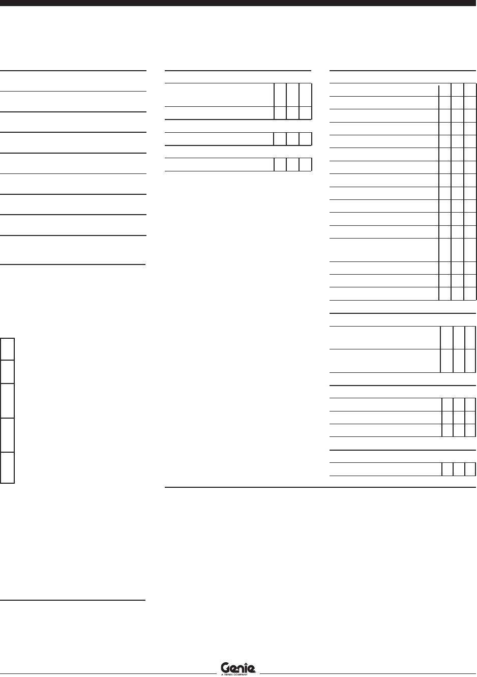
Inspection Checklist
Daily or every 8 hours A
Quarterly or every 250 hours A + B
Semi-annually or every 500 hours A + B + C
Annually or every 1000 hours A + B + C + D
Two year or every 2000 hours A + B + C + D + E
Maintenance Inspection Report
The maintenance inspection report contains
checklists for each type of scheduled inspection.
Make copies of the
Maintenance Inspection Report
to use for each inspection. Store completed forms
for three years.

Genie Industries USA
18340 NE 76th Street
PO Box 97030
Redmond, WA 98073-9730
(425) 881-1800
Copyright © 2002 by Genie Industries. Genie® is a registered trademark of Genie
Industries. Rev B
Genie UK
The Maltings, Wharf Road
Grantham, Lincolnshire
NG31- 6BH England
(44) 1476-584333
Pre-DeliverPre-Deliver
Pre-DeliverPre-Deliver
Pre-Deliver
y Preparationy Preparation
y Preparationy Preparation
y Preparation
Pre-Delivery Preparation Y N R
Pre-operation inspection
completed
Maintenance items completed
Function tests completed
Model
Serial number
Date
Machine owner
Inspected by (print)
Inspector signature
Inspector title
Inspector company
Instructions
Use the operator’s manual on your machine.
The Pre-delivery Preparation consists of completing
the Pre-operation Inspection, the Maintenance items
and the Function Tests.
Use this form to record the results. Place a check in
the appropriate box after each part is completed.
Follow the instructions in the operator’s manual.
If any inspection receives an N, remove the machine
from service, repair and re-inspect it. After repair,
place a check in the R box.
Legend
Y = yes, completed
N = no, unable to complete
R = repaired
Comments
Fundamentals
It is the responsibility of the dealer to perform the
Pre-delivery Preparation.
The Pre-delivery Preparation is performed prior to
each delivery. The inspection is designed to discover if
anything is apparently wrong with a machine before it
is put into service.
A damaged or modified machine must never be used.
If damage or any variation from factory delivered
condition is discovered, the machine must be tagged
and removed from service.
Repairs to the machine may only be made by a
qualified service technician, according to the
manufacturer's specifications.
Scheduled maintenance inspections shall be
performed by qualified service technicians, according
to the manufacturer's specifications and the
requirements listed in the responsibilities manual.

Section 3 • Scheduled Maintenance Procedures August 2005
3 - 4 GR-8 • GR-12 • GR-15 Part No. 72965
This page intentionally left blank.
Section 3 • Scheduled Maintenance ProceduresApril 2006
Part No. 72965 GR-8 • GR-12 • GR-15 3 - 5
Maintenance Inspection Report
Model
Serial number
Date
Hour meter
Machine owner
Inspected by (print)
Inspector signature
Inspector title
Inspector company
Checklist A - Rev B YNR
A-1 Pre-operation
inspection
A-2 Function tests
Perform after 40 hours:
A-3 30 day service
Perform every 100 hours:
A-4 Grease steer yokes
Checklist B - Rev B YNR
B-1 Batteries
B-2 Electrical wiring
B-3 Tires and wheels
B-4 Lifting chain
B-5 Clean columns
B-6 Sequencing cables
B-7 Emergency stop
B-8 Key switch
B-9 Horn (if equipped)
B-10 Drive brakes
B-11 Drive speed - stowed
B-12 Drive speed - raised
B-13 Flashing beacon
(if equipped)
B-14 Alarm (if equipped)
B-15 Hydraulic oil analysis
B-16 Breather cap
Checklist C - Rev C YNR
C-1 Grease platform
overload (if equipped)
C-2 Test platform overload
(if equipped)
Checklist D - Rev C YNR
D-1 Inspect Mast
D-2 Lubricate lifting chains
D-3 Hydraulic filter
Checklist E - Rev B YNR
E-1 Hydraulic oil
Instructions
· Make copies of this report to use for
each inspection.
· Select the appropriate checklist(s) for
the type of inspection to be
performed.
Daily or 8 hours
Inspection: A
Quarterly or 250 hours
Inspection: A+B
Semi-annually or
500 hours
Inspection: A+B+C
Annually or
1000 hours
Inspection: A+B+C+D
Two year or
2000 hours
Inspection: A+B+C+D+E
· Place a check in the appropriate box
after each inspection procedure is
completed.
· Use the step-by-step procedures in
this section to learn how to perform
these inspections.
· If any inspection receives an “N”, tag
and remove the machine from service,
repair and re-inspect it. After repair,
place a check in the “R” box.
Legend
Y = yes, acceptable
N = no, remove from service
R = repaired
Comments

REV B
Section 3 • Scheduled Maintenance Procedures
August 2005
3 - 6 GR-8 • GR-12 • GR-15 Part No. 72965
A-1
Perform Pre-operation Inspection
Completing a Pre-operation Inspection is essential
to safe machine operation. The Pre-operation
Inspection is a visual inspection performed by the
operator prior to each work shift. The inspection is
designed to discover if anything is apparently
wrong with a machine before the operator performs
the function tests. The Pre-operation Inspection
also serves to determine if routine maintenance
procedures are required.
Complete information to perform this procedure is
available in the appropriate operator's manual.
Refer to the Operator's Manual on your machine.
Checklist A Procedures
A-2
Perform Function Tests
Completing the function tests is essential to safe
machine operation. Function tests are designed to
discover any malfunctions before the machine is
put into service. A malfunctioning machine must
never be used. If malfunctions are discovered, the
machine must be tagged and removed from
service.
Complete information to perform this procedure is
available in the appropriate operator's manual.
Refer to the Operator's Manual on your machine.

REV B
Section 3 • Scheduled Maintenance Procedures
August 2005
Part No. 72965 GR-8 • GR-12 • GR-15 3 - 7
CHECKLIST A PROCEDURES
A-3
Perform 30 Day Service
The 30 day maintenance procedure is a one time
procedure to be performed after the first 30 days or
40 hours of usage. After this interval, refer to the
maintenance tables for continued scheduled
maintenance.
1 Perform the following maintenance procedures:
· B-3 Inspect the Tires and Wheels
(including castle nut torque)
· D-4 Replace the Hydraulic Tank
Return Filter
A-4
Grease the Steer Yokes
Genie specifications require that
this procedure be performed every
100 hours of operation.
Regular application of lubrication to the steer yokes
is essential to good machine performance and
service life. Continued use of an insufficiently
greased steer yoke will result in component
damage.
1 Locate the grease fitting on the top of the steer
yoke.
2 Pump multipurpose grease into the steer yoke
until the steer yoke is full and grease is being
forced past the bearings. Repeat this step for
the other steer yoke.
Grease specification
Chevron Ultra-duty grease, EP NLGI 2 (lithium based)
or equivalent

REV B
Section 3 • Scheduled Maintenance Procedures
August 2005
3 - 8 GR-8 • GR-12 • GR-15 Part No. 72965
Checklist B Procedures
B-1
Inspect the Batteries
Proper battery condition is essential to good
machine performance and operational safety.
Improper fluid levels or damaged cables and
connections can result in component damage and
hazardous conditions.
Electrocution hazard. Contact with
electrically charged circuits could
result in death or serious injury.
Remove all rings, watches and
other jewelry.
Bodily injury hazard. Batteries
contain acid. Avoid spilling or
contacting battery acid. Neutralize
battery acid spills with baking soda
and water.
Perform this procedure after fully
charging the batteries.
For a more accurate determination
of battery condition, fully charge
the batteries and allow the
batteries to rest 24 hours before
performing this procedure to allow
the battery cells to equalize.
1 Put on protective clothing and eye wear.
2 Be sure that the battery cable connections are
free of corrosion.
3 Be sure that the battery retaining fasteners and
cable connections are tight.
Models without maintenance-free or sealed
batteries:
4 Remove the battery vent caps from all batteries
and check the specific gravity of each battery
cell with a hydrometer.
Result: If any battery cell displays a specific
gravity of less than 1.026, the battery must be
replaced.
5 Check the battery acid level of each battery. If
needed, replenish with distilled water to the
bottom of the battery fill tube. Do not overfill.
6 Install the battery vent caps.
All models:
7 Check each battery pack and verify that the
batteries are wired correctly. Refer to the
Battery Connection Diagram
decal on the
machine.
8 Inspect the battery charger plug and pigtail for
damage or excessive insulation wear. Replace
as required.
9 Connect the battery charger to a properly
grounded 115V/60Hz or 230V/60Hz single
phase AC power supply.
Result: The charger should operate and begin
charging the batteries.
For best results, use an extension
of adequate size with a length no
longer than 50 feet / 15 m.
If you have any further questions
regarding the battery charger
operation, please contact the
Genie Industries Scissor Service
Department.

REV B
Section 3 • Scheduled Maintenance Procedures
August 2005
Part No. 72965 GR-8 • GR-12 • GR-15 3 - 9
CHECKLIST B PROCEDURES
B-2
Inspect the Electrical Wiring
Maintaining electrical wiring in good condition is
essential to safe operation and good machine
performance. Failure to find and replace burnt,
chafed, corroded or pinched wires could result in
unsafe operating conditions and may cause
component damage.
Electrocution hazard. Contact with
hot or live circuits could result in
death or serious injury. Remove all
rings, watches and other jewelry.
1 Inspect the underside of the chassis for
damaged or missing ground straps.
2 Inspect the following areas for burnt, chafed,
corroded and loose wires:
· Mast cable
· Platform controls
· Power to platform wiring
3 Inspect the following areas for burnt, chafed,
corroded and loose wires:
· Ground control panel
· Hydraulic power unit
4 Inspect for a liberal coating of dielectric grease
in the following locations:
· Between the ECM and platform controls
· All wire harness connectors
· Level sensor
5 Turn the key switch to ground control and pull
out the red Emergency Stop button to the on
position at both the ground and platform
controls.
6 Raise the platform approximately 8 feet / 2.4 m
from the ground.
7 Place a lifting strap from an overhead crane
under the platform. Support the platform. Do not
apply any lifting pressure.
platform railings can be damaged
if they are used to lift the platform.
Do not attach the lifting strap to
the platform railings.
8 Inspect the center chassis area for burnt,
chafed and pinched cables.
9 Open the battery tray cover.
10 Inspect the battery tray for burnt, chafed and
pinched cables.
11 Close the battery tray cover.
12 Remove the strap from the platform.
13 Lower the platform to the stowed position and
turn the machine off.

REV B
Section 3 • Scheduled Maintenance Procedures
August 2005
3 - 10 GR-8 • GR-12 • GR-15 Part No. 72965
B-3
Inspect the Tires and Wheels
(including castle nut torque)
Maintaining the tires and wheels in good
condition is essential to safe operation and good
performance. Tire and/or wheel failure could result
in a machine tip-over. Component damage may
also result if problems are not discovered and
repaired in a timely fashion.
1 Check the tire surface and sidewalls for cuts,
cracks, punctures and unusual wear.
2 Check each wheel for damage, bends and
cracks.
3 Remove the cotter pin and check each castle
nut for proper torque. Refer to Section 2,
Specifications.
Always replace the cotter pin with
a new one when removing the
castle nut or when checking the
torque of the castle nut.
4 Install a new cotter pin. Bend the cotter pin to
lock it in place.
B-4
Check the Lifting Chain
Adjustments
Maintaining proper adjustment of the lifting chains
is essential to safe machine operation. Failure to
maintain proper chain adjustment could result in an
unsafe operating condition and may cause
component damage.
1 Fully lower the platform and measure the
maximum height of the machine. Refer to
Section 2,
Specifications
.
Result: The machine is not within specification.
Adjust the chains. Refer to Repair Procedure
3-4,
How to Adjust the Lifting Chains.
CHECKLIST B PROCEDURES

REV B
Section 3 • Scheduled Maintenance Procedures
August 2005
Part No. 72965 GR-8 • GR-12 • GR-15 3 - 11
B-5
Clean and Lubricate the Columns
Clean and properly lubricated columns are
essential to good machine performance and safe
operation. Extremely dirty conditions may require
that the columns be cleaned and lubricated more
often.
1 Raise the platform to the maximum height.
2 Place a lifting strap from an overhead crane
under the platform. Support the platform. Do not
apply any lifting pressure.
platform railings can be damaged
if they are used to lift the platform.
Do not attach the lifting strap to
the platform railings.
3 Visually inspect the inner and outer channels of
the columns for debris or foreign material. If
necessary, use a mild cleaning solvent to clean
the columns.
Bodily injury hazard. This
procedure will require the use of
additional access equipment. Do
not place ladders or scaffold on or
against any part of the machine.
Performing this procedure without
the proper skills and tools could
result in death or serious injury.
Dealer service is strongly
recommended.
4 If needed, apply a generous amount of
Boe-lube wax to the inside and outside
channels of each column.
CHECKLIST B PROCEDURES
B-6
Adjust the Sequencing Cables
Maintaining proper adjustment of the sequencing
cables is essential for safe machine operation. An
unsafe working condition exists if the sequencing
cables are improperly adjusted. A frequent check
allows the inspector to identify changes in the
sequencing cables operating condition that might
indicate damage.
1 Fully lower the platform.
2 Locate the compression spring on each
sequencing cable.
The spring is located between the
nylock nut and the upper
sequencing bracket.
a nylock nut
b spring
c upper sequencing bracket
d sequencing cable
a
c
b
d

REV B
Section 3 • Scheduled Maintenance Procedures
August 2005
3 - 12 GR-8 • GR-12 • GR-15 Part No. 72965
3 Confirm proper tension of each sequencing
cable by measuring the height of the spring
between the nylock nut and the upper
sequencing bracket.
Result: The measurement is within
specification. Proceed to step 7.
Result: The measurement is not within
specification. Proceed to step 4.
Sequencing cable spring specification
Measurement, compressed
15
/16 inch
2.4 cm
4 Adjust the spring compressed length by turning
the nylock nut clockwise to decrease the spring
length or counterclockwise to increase the
spring length.
not compress the spring to less
than specification.
5 Raise and lower the platform through three
complete cycles.
6 Repeat this procedure beginning with step 3.
7 Repeat steps 3 through 5 for each sequencing
cable as required.
B-7
Test the Emergency Stop
A properly functioning Emergency Stop is essential
for safe machine operation. An improperly
operating red Emergency Stop button will fail to
shut off power and stop all machine functions,
resulting in a hazardous situation.
As a safety feature, selecting
and operating the ground controls
will override the platform controls,
except the platform red
Emergency Stop button.
1 Turn the key switch to ground control and pull
out the red Emergency Stop button to the on
position at both the ground and platform
controls.
2 Push in the red Emergency Stop button at the
ground controls to the off position.
Result: No machine functions should operate.
3 Turn the key switch to platform control and pull
out the red Emergency Stop button to the on
position at both the ground and platform
controls.
4 Push down the red Emergency Stop button at
the platform controls to the off position.
Result: No machine functions should operate.
The red Emergency Stop button at
the ground controls will stop all
machine operation, even if the key
switch is switched to platform
control.
CHECKLIST B PROCEDURES

REV B
Section 3 • Scheduled Maintenance Procedures
August 2005
Part No. 72965 GR-8 • GR-12 • GR-15 3 - 13
B-8
Test the Key Switch
Proper key switch action and response is essential
to safe machine operation. The machine can be
operated from the ground or platform controls and
the activation of one or the other is accomplished
with the key switch. Failure of the key switch to
activate the appropriate control panel could cause
a hazardous operating situation.
Perform this procedure from the
ground using the platform controls.
Do not stand in the platform.
1 Pull out the red Emergency Stop button to the
on position at both the ground and platform
controls.
2 Turn the key switch to platform control.
3 Check the platform up/down function from the
ground controls.
Result: The machine functions should not
operate.
4 Turn the key switch to ground control.
5 Check the machine functions from the platform
controls.
Result: The machine functions should not
operate.
6 Turn the key switch to the off position.
7 Test the machine functions from the ground and
platform controls.
Result: No machine functions should operate.
CHECKLIST B PROCEDURES
B-9
Test the Automotive-style Horn
(if equipped)
The horn is activated at the platform controls and
sounds at the ground as a warning to ground
personnel. An improperly functioning horn will
prevent the operator from alerting ground
personnel of hazards or unsafe conditions.
1 Turn the key switch to platform control and
pull out the red Emergency Stop button to the
on position at both the ground and
platform controls.
2 Push down the horn button at the platform
controls.
Result: The horn should sound.
REV B
Section 3 • Scheduled Maintenance Procedures
August 2005
3 - 14 GR-8 • GR-12 • GR-15 Part No. 72965
B-11
Test the Drive Speed -
Stowed Position
Proper drive functions are essential to safe
machine operation. The drive function should
respond quickly and smoothly to operator control.
Drive performance should also be free of
hesitation, jerking and unusual noise over the
entire proportionally controlled speed range.
Perform this procedure with the
machine on a firm, level surface
that is free of obstructions.
1 Create start and finish lines by marking two
lines on the ground 40 feet / 12.2 m apart.
2 Turn the key switch to platform control and pull
out the red Emergency Stop button to the on
position at both the ground and platform
controls.
3 Lower the platform to the stowed position.
4 Move the lift/drive toggle switch to the drive
position.
5 Press the drive speed button (if equipped) until
the high speed (rabbit) light is illuminated.
6 Choose a point on the machine; i.e., contact
patch of a tire, as a visual reference for use
when crossing the start and finish lines.
7 Bring the machine to top drive speed before
reaching the start line. Begin timing when your
reference point on the machine crosses the
start line.
8 Continue at full speed and note the time when
your reference point on the machine passes
over the finish line. Refer to Section 2,
Specifications
.
B-10
Test the Drive Brakes
Proper brake action is essential to safe machine
operation. The drive brake function should operate
smoothly, free of hesitation, jerking and unusual
noise. Hydraulically-released individual wheel
brakes can appear to operate normally when not
fully operational.
Perform this procedure with the
machine on a firm, level surface
that is free of obstructions.
Be sure the platform extension
deck is fully retracted and the
platform is in the stowed position.
1 Mark a test line on the ground for reference.
2 Turn the key switch to platform control and pull
out the red Emergency Stop button to the on
position at both the ground and platform
controls.
3 Lower the platform to the stowed position.
4 Move the lift/drive toggle switch to the drive
position.
5 Press the drive speed button (if equipped) until
the high speed (rabbit) light is illuminated.
6 Choose a point on the machine; i.e., contact
patch of a tire, as a visual reference for use
when crossing the test line.
7 Bring the machine to top drive speed before
reaching the test line. Release the function
enable switch or the joystick when your
reference point on the machine crosses the test
line.
8 Measure the distance between the test line and
your machine reference point. Refer to Section
2,
Specifications
.
The brakes must be able to hold
the machine on any slope it is able
to climb
CHECKLIST B PROCEDURES

REV B
Section 3 • Scheduled Maintenance Procedures
August 2005
Part No. 72965 GR-8 • GR-12 • GR-15 3 - 15
CHECKLIST B PROCEDURES
B-12
Test the Drive Speed -
Raised Position
Proper drive functions are essential to safe
machine operation. The drive function should
respond quickly and smoothly to operator control.
Drive performance should also be free of
hesitation, jerking and unusual noise over the
entire proportionally controlled speed range.
Perform this procedure with the
machine on a firm, level surface
that is free of obstructions.
1 Create start and finish lines by marking two
lines on the ground 40 feet / 12.2 m apart.
2 Turn the key switch to platform control and pull
out the red Emergency Stop button to the on
position at both the ground and platform
controls.
3 Raise the platform approximately 4 feet / 1.2 m
from the ground.
4 Move the lift/drive toggle switch to the drive
position.
5 Press the drive speed button (if equipped) until
the high speed (rabbit) light is illuminated..
6 Choose a point on the machine; i.e., contact
patch of a tire, as a visual reference for use
when crossing the start and finish lines.
7 Bring the machine to top drive speed before
reaching the start line. Begin timing when your
reference point on the machine crosses the
start line.
8 Continue at full speed and note the time when
your reference point on the machine passes
over the finish line. Refer to Section 2,
Specifications
.
B-13
Test the Flashing Beacon
(if equipped)
Flashing beacons are used to alert operators and
ground personnel of machine proximity and
motion. The flashing beacons are located on both
sides of the mast.
1 Turn the key switch to ground control and pull
out the red Emergency Stop button to the on
position at both the ground and platform
controls.
Result: The beacons should flash.
2 Turn the key switch to platform controls.
Result: The beacons should flash.

REV B
Section 3 • Scheduled Maintenance Procedures
August 2005
3 - 16 GR-8 • GR-12 • GR-15 Part No. 72965
CHECKLIST B PROCEDURES
B-14
Test the Alarm Package
(if equipped)
The alarm package includes:
· Travel alarm
· Descent alarm
· Flashing beacons
Alarms and beacons are used to alert operators
and ground personnel of machine proximity and
motion. The descent alarm and travel alarm are
located in the ground control box. The flashing
beacons are located on both sides of the mast.
The alarms and beacons will
operate with key switch turned to
either ground or platform controls.
1 Turn the key switch to ground control and pull
out the red Emergency Stop button to the on
position at both the ground and platform
controls.
Result: Both flashing beacons should be on and
flashing.
2 Activate the platform up/down toggle switch in
the down position, hold for a moment and then
release it.
Result: The descent alarm should sound when
the toggle switch is held down.
3 Turn the key switch to platform controls.
Result: bopth flashing beacons should be on
and flashing.
4 Move the lift/drive select switch to the lift
position.
5 Press and hold the function enable switch on
the joystick controller (joystick). Move the
joystick in the direction indicated by the yellow
arrow on the control panel, hold for a moment
and then release it.
Result: The descent alarm should sound when
the joystick is held down.
6 Move the lift/drive selector switch to the drive
position.
7 Press and hold the function enable switch on
the joystick. Move the joystick off center, hold
for a moment and then release it. Move the
joystick off center in the opposite direction, hold
for a moment and then release it.
Result: The travel alarm should sound when the
joystick is moved off center in either direction.

REV B
Section 3 • Scheduled Maintenance Procedures
August 2005
Part No. 72965 GR-8 • GR-12 • GR-15 3 - 17
CHECKLIST B PROCEDURES
B-15
Perform Hydraulic Oil Analysis
Replacement or testing of the hydraulic oil is
essential for good machine performance and
service life. Dirty oil may cause the machine to
perform poorly and continued use may cause
component damage. Extremely dirty conditions
may require oil changes to be performed more
often.
Before replacing the hydraulic oil,
the oil may be tested by an oil
distributor for specific levels of
contamination to verify that
changing the oil is necessary. If
the hydraulic oil is not replaced
at the two year inspection, test
the oil quarterly. Replace the oil
when it fails the test. See E-1,
Test or Replace the Hydraulic Oil.
B-16
Inspect the Hydraulic Tank Cap
Venting System
The hydraulic tank is a vented-type tank. The
breather cap has an internal air filter that can
become clogged and may cause the power unit to
operate improperly. If the breather cap is damaged
or improperly installed, impurities can enter the
hydraulic system which may cause component
damage. Extremely dirty conditions may require
that the cap be inspected more often.
1 Remove the breather cap from the hydraulic
tank.
2 Check for proper venting.
Result: Air passes through the fuel tank cap.
Proceed to step 4.
Result: If air does not pass through the cap,
clean or replace the cap. Proceed to step 3.
When checking for positive tank
cap venting, air should pass freely
through the cap.
3 Using a mild solvent, carefully wash the cap
venting system. Dry using low pressure
compressed air. Repeat this procedure
beginning with step 2.
4 Install the breather cap onto the hydraulic tank.

REV C
Section 3 • Scheduled Maintenance Procedures
April 2006
3 - 18 GR-8 • GR-12 • GR-15 Part No. 72965
C-1
Replace the
Hydraulic Tank Breather Cap -
Models with Optional Hydraulic Oil
The hydraulic tank is a vented-type tank. The
breather cap has an internal air filter that can
become clogged or, over time, can deteriorate. If
the breather cap is faulty or improperly installed,
impurities can enter the hydraulic system which
may cause component damage. Extremely dirty
conditions may require that the cap be inspected
more often.
1 Remove and discard the hydraulic tank breather
cap.
2 Install a new cap onto the tank.
Checklist C Procedures
C-2
Grease the Platform Overload
Mechanism (if equipped)
Genie specifications require
that this procedure be performed
every 500 hours or 6 months,
whichever comes first. Perform
this procedure more often if dusty
conditions exist.
Application of lubrication to the platform overload
mechanism is essential to safe machine operation.
Continued use of an improperly greased platform
overload mechanism could result in the system not
sensing an overloaded platform condition and will
result in component damage.
1 Locate the grease fittings on each pivot pin of
the platform overload assembly.
2 Thoroughly pump grease into each grease
fitting using a multi-purpose grease.

REV C
Section 3 • Scheduled Maintenance Procedures
April 2006
Part No. 72965 GR-8 • GR-12 • GR-15 3 - 19
C-3
Test the Platform Overload
System (if equipped)
Genie specifications require that
this procedure be performed every
500 hours or 6 months, whichever
comes first.
Testing the platform overload system regularly is
essential to safe machine operation. Continued
use of an improperly operating platform overload
system could result in the system not sensing an
overloaded platform condition. Machine stability
could be compromised resulting in the machine
tipping over.
Perform this procedure with the
machine on a firm, level surface.
1 Turn the key switch to platform control and pull
out the red Emergency Stop button to the on
position at both the ground and platform
controls.
2 Determine the maximum platform capacity.
Refer to the machine serial plate.
3 Using a suitable lifting device, place an
appropriate test weight equal to the maximum
platform capacity in the center of the platform
floor. Refer to Section 2,
Specifications
.
Result: The overload alarm at the platform
controls should not sound, indicating a normal
condition.
Result: The overload alarm at the platform
controls sounds. The platform overload system
is not operating properly. Refer to Repair
Procedure 10-1,
Calibrate the Platform
Overload System (if equipped).
4 Add an additional weight to the platform not to
exceed 20% of the maximum rated load. Refer
to the machine serial plate.
Result: The overload alarm at the platform
controls sounds. The platform overload system
is operating properly.
Result: The overload alarm at the platform
controls does not sound. The platform overload
system is not operating properly. Refer to
Repair Procedure 10-1,
Calibrate the Platform
Overload System (if equipped).
5 Test all machine functions from the platform
controls.
Result: All platform control functions should not
operate.
6 Turn the key switch to ground control.
7 Test all machine functions from the ground
controls.
Result: All ground control functions should not
operate.
CHECKLIST C PROCEDURES

REV C
Section 3 • Scheduled Maintenance Procedures
April 2006
3 - 20 GR-8 • GR-12 • GR-15 Part No. 72965
8 Lift the test weight off the platform floor using a
suitable lifting device.
Result: The overload alarm at the platform
controls should not sound, indicating a normal
condition.
Result: The overload alarm at the platform
controls sounds. The platform overload system
is not operating properly. See D-1,
Calibrate the
Platform Overload System (if equipped).
9 Test all machine functions from the ground
controls.
Result: All ground control functions should
operate normally.
10 Turn the key switch to platform control.
11 Test all machine functions from the platform
controls.
Result: All platform control functions should
operate.
If the platform overload system is
not operating properly, see D-1,
Calibrate the Platform Overload
System (if equipped).
CHECKLIST C PROCEDURES

REV C
Section 3 • Scheduled Maintenance Procedures
April 2006
Part No. 72965 GR-8 • GR-12 • GR-15 3 - 21
Checklist D Procedures
D-1
Inspect the Mast Assembly
for Wear
Detection of excessive or unusual wear in the mast
assembly is essential for safe machine operation.
An unsafe working condition exists if the mast
assembly has excessive wear and/or does not
operate smoothly, free of hesitation and binding.
1 Remove the mast covers.
2 Raise the platform until approximately
4 inches / 10 cm of each column is visible.
3 Visually inspect the top of each column for
clearance between the roller wheels and the
adjacent column surface.
Result: There should be an equal amount of
distance between the roller wheel/slider block
and the column on each side.
If mast inspection results in a
measurement that is not within
specification, refer to Repair
procedure 3-2,
How to Adjust the
Glide Pads.
4 Loosen but do not remove the adjustment nut
on the sequencing cable located at the top of
the first column.
5 Raise the platform approximately 3 feet / 1 m
above the top of the drive chassis.
6 Place piece of 0.75 inch / 1.9 cm thick plywood
ont top of the drive chassis.
7 Place a jack stand on the top of the plywood,
centered under the platform. Adjust the jack
stand height to 24 inches / 61 cm.
8 Lower the platform onto the jack stand just
enough to take the weight off the lifting chains.
Crushing hazard. Keep hands
clear of the jack stand when
lowering the platform.
GR-15 shown
a mast cover
b idler wheel
c spacer
a
b
c

REV C
Section 3 • Scheduled Maintenance Procedures
April 2006
3 - 22 GR-8 • GR-12 • GR-15 Part No. 72965
CHECKLIST D PROCEDURES
9 Inspect each idler wheel for the following:
· Excessive wear on the side flanges
· Unusual wear
· Movement side to side in excess of
0.040 inch / 1 mm
· Any wheel movement front to back
If idler wheel inspection results in
a condition that is not within
specification, refer to Repair
Procedure 3-1,
How to Assemble
the Mast.
10 Raise the platform slightly and remove the jack
stand and the piece of plywood. Lower the
platform to the stowed position.
11 Install the mast covers and adjust the
sequencing cable. See B-6,
Adjust the
Sequencing Cables.
D-2
Lubricate the Lifting Chains
Lubricated chains are essential to good machine
performance and safe operation. Extremely dirty
conditions may require that the chains be cleaned
and lubricated more often.
1 Raise the platform to the maximum height.
2 Place a lifting strap from an overhead crane
under the platform. Support the platform. Do not
apply any lifting pressure.
platform railings can be damaged
if they are used to lift the platform.
Do not attach the lifting strap to
the platform railings.
3 Lubricate each chain with a dry-type spray
lubricant.
Bodily injury hazard. This
procedure will require the use of
additional access equipment. Do
not place ladders or scaffold on or
against any part of the machine.
Performing this procedure without
the proper skills and tools could
result in death or serious injury.
Dealer service is strongly
recommended.

REV C
Section 3 • Scheduled Maintenance Procedures
April 2006
Part No. 72965 GR-8 • GR-12 • GR-15 3 - 23
D-3
Replace the Hydraulic Tank
Return Filter
Replacement of the hydraulic tank return filter is
essential for good machine performance and
service life. A dirty or clogged filter may cause the
machine to perform poorly and continued use may
cause component damage. Extremely dirty
conditions may require that the filter be replaced
more often.
Burn hazard. Beware of hot oil.
Contact with hot oil may cause
severe burns.
The hydraulic tank return filter is
mounted on the function manifold
next to the hydraulic power unit.
1 Clean the area around the oil filter. Remove the
filter with an oil filter wrench.
2 Apply a thin layer of oil to the new oil filter
gasket.
3 Install the new filter and tighten it securely by
hand.
4 Use a permanent ink marker to write the date
and number of hours from the hour meter onto
the filter.
CHECKLIST D PROCEDURES
5 Turn the key switch to ground control and pull
out the red Emergency Stop button to the on
position at both the ground and platform
controls.
6 Activate and hold the platform up toggle switch.
7 Inspect the filter and related components to
be sure that there are no leaks.
8 Clean up any oil that may have spilled.
REV B
Section 3 • Scheduled Maintenance Procedures
August 2005
3 - 24 GR-8 • GR-12 • GR-15 Part No. 72965
Checklist E Procedure
E-1
Test or Replace the Hydraulic Oil
Replacement or testing of the hydraulic oil is
essential for good machine performance and
service life. Dirty oil and suction strainers may
cause the machine to perform poorly and
continued use may cause component damage.
Extremely dirty conditions may require oil changes
to be performed more frequently.
The machine uses Dexron
equivalent hydraulic oil. Before
replacing the hydraulic oil, the oil
may be tested by an oil distributor
for specific levels of contamination
to verify that changing the oil is
necessary. If the hydraulic oil is
not replaced at the two year
inspection, test the oil quarterly.
Replace the oil when it fails the
test.
When removing a hose assembly
or fitting, the O-ring on the fitting
and/or hose end must be replaced
and then torqued to specification
during installation. Refer to
Section 2,
Hydraulic Hose and
Fitting Torque Specifications.
1 Raise the platform approximately 4 feet / 1.2 m.
2 Place a lifting strap from an overhead crane
under the platform. Support the platform. Do not
apply any lifting pressure.
platform railings can be damaged
if they are used to lift the platform.
Do not attach the lifting strap to
the platform railings.
3 Disconnect the battery pack from the machine.
Electrocution hazard. Contact with
electrically charged circuits could
result in death or serious injury.
Remove all rings, watches and
other jewelry.
4 Remove the drive chassis cover.
5 Remove the drain plug from the hydraulic tank
and allow all of the oil to drain into a suitable
container. Refer to Section 2,
Specifications
.
Bodily injury hazard Spraying
hydraulic oil can penetrate and
burn skin. Loosen hydraulic
connections very slowly to allow
the oil pressure to dissipate
gradually. Do not allow oil to squirt
or spray.
6 Tag, disconnect and plug the supply hose from
the hydraulic power unit to the tank.
7 Before serial number GR01-249: Tag,
disconnect and plug the return hose from the
function manifold to tank at the return filter. Cap
the fitting on the return filter housing.
After serial number GR01-248: Tag,
disconnect and plug the return hose from the
return filter to tank at the tank.

REV B
Section 3 • Scheduled Maintenance Procedures
August 2005
Part No. 72965 GR-8 • GR-12 • GR-15 3 - 25
CHECKLIST E PROCEDURE
8 Remove the hydraulic tank mounting fasteners
and remove the tank from the machine.
9 Remove the suction strainer from the tank and
clean it using a mild solvent.
10 Clean the inside of the hydraulic tank using a
mild solvent.
11 Install the suction strainer using thread sealant
on the threads. Torque to specification.
12 Install and tighten the hydraulic tank drain plug
using thread sealant on the threads. Torque to
specification.
13 Install the hydraulic tank and install and tighten
the hydraulic tank retaining fasteners. Torque to
specification.
14 Connect the suction hose to the strainer and
torque to specification.
15 Before serial number GR01-249: Connect the
return hose to the return filter and torque to
specification.
After serial number GR01-248: Connect the
return hose to the tank and torque to
specification.
16 Connect the battery pack to the machine.
Electrocution hazard. Contact with
electrically charged circuits could
result in death or serious injury.
Remove all rings, watches and
other jewelry.
17 Fill the tank with hydraulic oil until the fluid is at
the FULL indicator on the hydraulic tank. Do not
overfill.
18 Activate the pump to fill the hydraulic system
with oil and bleed the system of air.
pump can be damaged if operated
without oil. Be careful not to empty
the hydraulic tank while in the
process of filling the hydraulic
system. Do not allow the pump to
cavitate.
19 Repeat steps 17 through 18 until the hydraulic
system and tank are both full.
20 Clean up any oil that may have spilled. Properly
discard the used oil.
21 Install the drive chassis cover and securely
tighten the fasteners. Do not over tighten.
22 Lower the platform to the stowed position.
Hydraulic tank torque specifications
Hydraulic tank retaining fasteners, dry 35 in-lbs
4 Nm
Hydraulic tank retaining fasteners, lubricated 26 in-lbs
2.9 Nm
Hydraulic tank drain plug, dry 40 in-lbs
4.5 Nm
Hydraulic tank drain plug, lubricated 30 in-lbs
3.4 Nm

Section 3 • Scheduled Maintenance Procedures April 2006
3 - 26 GR-8 • GR-12 • GR-15 Part No. 72965
This page intentionally left blank.

Section 4 • Repair ProceduresAugust 2005
Part No. 72965 GR-8 • GR-12 • GR-15 4 - 1
Repair Procedures
Observe and Obey:
Repair procedures shall be completed by a
person trained and qualified on the repair of this
machine.
Immediately tag and remove from service a
damaged or malfunctioning machine.
Repair any machine damage or malfunction
before operating the machine.
Before Repairs Start:
Read, understand and obey the safety rules
and operating instructions in the appropriate
operator's manual on your machine.
Be sure that all necessary tools and parts are
available and ready for use.
Read each procedure completely and adhere to
the instructions. Attempting shortcuts may
produce hazardous conditions.
Unless otherwise specified, perform each repair
procedure with the machine in the following
configuration:
· Machine parked on a firm, level surface
· Platform in the stowed position
· Key switch in the off position with the key
removed
· The red Emergency Stop button in the off
position at both ground and platform controls
· Wheels chocked
· All external AC power supply disconnected
from the machine
About This Section
Most of the procedures in this section should only
be performed by a trained service professional
in a suitably equipped workshop. Select the
appropriate repair procedure after troubleshooting
the problem. Perform disassembly procedures to
the point where repairs can be completed. To
re-assemble, perform the disassembly steps in
reverse order.
Symbols Legend
Safety alert symbol—used to alert
personnel to potential personal
injury hazards. Obey all safety
messages that follow this symbol
to avoid possible injury or death.
Red—used to indicate the
presence of an imminently
hazardous situation which, if not
avoided, will result in death or
serious injury.
Orange—used to indicate the
presence of a potentially
hazardous situation which, if not
avoided, could result in death or
serious injury.
Yellow with safety alert symbol—
used to indicate the presence of a
potentially hazardous situation
which, if not avoided, may cause
minor or moderate injury.
Yellow without safety alert
symbol—used to indicate the
presence of a potentially
hazardous situation which, if not
avoided, may result in property
damage.
Green—used to indicate operation
or maintenance information.
Indicates that a specific result is expected after
performing a series of steps.
Indicates that an incorrect result has occurred
after performing a series of steps.

Section 4 • Repair Procedures
REV B
August 2005
4 - 2 GR-8 • GR-12 • GR-15 Part No. 72965
Platform Controls
The joystick controller (joystick) should operate
smoothly and provide proportional drive speed
control over its entire range of motion.
The joystick is connected to the motor controller
located in the drive chassis. There are no
adjustments needed on the joystick. For further
assistance, consult the Genie Industries Service
Department.
For further information or assistance, consult the
Genie Industries Service Department.
1-1
Circuit Board
How to
Remove the Circuit Board
1 Tag and disconnect the platform controls from
the machine. Remove the control box from the
machine and place it on a workbench.
2 Remove the fasteners securing the base to the
platform control box. Open the box.
3 Remove the ties securing the wire harness.
4 Remove the alarm and horn assembly button
from the platform control box (if equipped).
5 Tag and disconnect the wire harnesses
connectors from the circuit board.
Electrostatic discharge (ESD) can
damage printed circuit board
components. Maintain firm contact
with a metal part of the machine
that is grounded at all times when
handling printed circuit boards OR
use a grounded wrist strap.
6 Remove the circuit board retaining fasteners
and remove the circuit board from the box.
a joystick controller JC3
b horn H3
c lift/drive select toggle switch TS16
d horn button BN5
e red Emergency Stop button P2
f platform controls circuit board U3
R
L
C
B
1
5
4
3
2
b
d
5
8
6
2
4
7
1
H3
HORN
BN5
HORN
P2
EMERGENCY
STOP
JC3
JOYSTICK
CONTROLLER
TS16
LIFT/DRIVE SELECT
TOGGLE SWITCH
e
U3
PLATFORM
CONTROLS
CIRCUIT
BOARD
a
c
f

Section 4 • Repair Procedures
REV B
August 2005
Part No. 72965 GR-8 • GR-12 • GR-15 4 - 3
PLATFORM CONTROLS
1-2
Controller Adjustments
How to
Calibrate the Potentiometer
1 Tag and disconnect the platform controls from
the machine. Remove the control box from the
machine and place it on a workbench.
2 Remove the retaining fasteners securing the
base to the platform control box. Open the box.
3 Remove the ties securing the wire harness.
4 Tag and disconnect the joystick from the wire
harnesses.
Electrostatic discharge (ESD) can
damage printed circuit board
components. Maintain firm contact
with a metal part of the machine
that is grounded at all times when
handling printed circuit boards OR
use a grounded wrist strap.
5 Remove the joystick retaining fasteners and
remove the joystick from the control box.
6 Remove the circuit board from the joystick. Turn
the circuit board over to access the
potentiometer shaft.
When installed, the potentiometer
shaft and joystick coupler engages
the joystick slave gear.
7 Set a multimeter to read ohm resistance.
The multimeter, when set to read
ohm resistance, should be
capable of reading 20k ohms.
8 Connect the leads from the multi meter to the
yellow and red wires of the joystick harness at
the harness connector.
9 Note the orientation of the joystick coupler
installed onto the potentiometer shaft. Loosen
the set-screw and remove the coupler. Set the
coupler to the side.
a circuit board
b potentiometer shaft
c coupler
d set screw
e circuit board bottom edge
10 Using the multi meter as a guide, rotate the
potentiometer shaft until reaching the highest
reading on the meter. Note the result.
11 Install the coupler onto the potentiometer shaft
in the same orientation as removed, with the
set-screw side of the coupler installed parallel
to the bottom edge of the circuit board.
12 Install the circuit board and fasteners onto the
joystick. Securely tighten the fasteners. Do not
over tighten.
d
c
a
b
e

Section 4 • Repair Procedures
REV B
August 2005
4 - 4 GR-8 • GR-12 • GR-15 Part No. 72965
13 Note the reading on the multi meter display.
Result: The reading is within 10% of the result
from step 10.
Result: The reading is not within 10% of the
result from step 10. Repeat this procedure
beginning with step 11.
14 Install the joystick into the platform control box.
Install and securely tighten the retaining
fasteners. Do not over tighten.
15 Securely connect the joystick to the control box
wire harness.
16 Install the base onto the control box. Install and
securely tighten the retaining fasteners. Do not
over tighten.
How to
Calibrate the High Speed Trimpot
(Adjusting the Stowed Drive Speed)
To calibrate the raised drive
speed, see 4-3,
How to Calibrate
the Raised Drive Speed Trimpot
(Adjusting the Raised Drive
Speed).
1 Remove the base from the platform control box.
2 Locate the high speed trimpot on the circuit
board of the joystick assembly.
The high speed trimpot is located
adjacent to the potentiometer and
the single red wire on the circuit
board of the joystick.
3 Adjust the trimpot to acheive the specified drive
speed. Turn the trimpot screw clockwise to
decrease the drive speed or counterclockwise
to increase the drive speed.
4 Install the base onto the control box. Install and
securely tighten the fasteners. Do not over
tighten.
5 Confirm the stowed drive speed. Refer to
Maintenance Procedure B-11,
Test the Drive
Speed - Stowed Position
.
a high speed trimpot
b circuit board
c potentiometer
PLATFORM CONTROLS
RD
RD
YL
c
a
b

Section 4 • Repair Procedures
REV A
August 2005
Part No. 72965 GR-8 • GR-12 • GR-15 4 - 5
Platform Components
2-1
Platform
How to
Remove the Platform
1 Raise the platform approximately 3 feet / 1 m.
2 Place support blocks between the platform and
the drive chassis. Lower the platform onto the
blocks.
Crushing hazard. Keep away from
the lowering platform.
3 Unlatch and remove the platform control box
from the platform and set it aside.
4 Tag and disconnect the extension deck limit
switch (if equipped) wiring at the junction box.
5 Remove the mounting fasteners from the
platform.
6 Pull the platform away from the mast and
remove it from the machine.
Bodily injury hazard. If a platform
is being replaced, be sure that all
appropriate safety and
instructional decals are applied to
the new platform.
2-2
Platform Extension
How to
Remove the Platform Extension
1 Remove the Platform, See 2-1,
How to Remove
the Platform
.
2 Remove the outer platform railing assembly.
3 Remove the slide blocks from the outer
platform.
4 Activate the foot release latch and slide the
extension platform out from under the platform.

Section 4 • Repair Procedures
REV B
August 2005
4 - 6 GR-8 • GR-12 • GR-15 Part No. 72965
Mast Components
3-1
Mast
Bodily injury hazard. This
procedure requires specific repair
skills, lifting equipment and a
suitable workshop. Attempting this
procedure without these skills and
tools could result in death or
serious injury and significant
component damage. Dealer
service is strongly recommended.
How to
Remove the Mast Assembly
Perform this procedure on a firm,
level surface.
Perform this procedure with the
mast in the stowed position.
When removing a hose assembly
or fitting, the O-ring on the fitting
and/or hose end must be replaced
and then torqued to specification
during installation. Refer to
Section 2,
Hydraulic Hose and
Fitting Torque Specifications.
1 Remove the platform. See 2-1,
How to Remove
the Platform
.
2 Open the battery covers.
3 Remove the fasteners securing the rear access
cover to the chassis. Remove the cover.
4 Tag and disconnect the wire harness from the
valve coil at the base of the lift cylinder.
5 Tag, disconnect and plug the lift cylinder
hydraulic hoses. Cap the fittings on the
cylinder.
Bodily injury hazard. Spraying
hydraulic oil can penetrate and
burn skin. Loosen hydraulic
connections very slowly to allow
the oil pressure to dissipate
gradually. Do not allow oil to squirt
or spray.
6 Remove the solenoid valve from the lift cylinder.
Plug the opening in the cylinder manifold.
7 Remove the fasteners from the drive speed limit
switch (LS5) mounted at the top of the number
1 column. Do not disconnect the wiring.
8 Remove the platform controls. Remove the
fasteners from the power to platform junction
box mounting bracket. Do not disconnect the
wiring.
Cables can be damaged if they
are kinked or pinched.
9 Attach a lifting strap of suitable capacity from an
overhead crane to the lifting eye at the top of
the mast. Support the mast. Do not apply any
lifting pressure.
10 Place two 4 x 4 x 24 inch / 10 x 10 x 60 cm
blocks across the top of the drive chassis.

Section 4 • Repair Procedures
REV B
August 2005
Part No. 72965 GR-8 • GR-12 • GR-15 4 - 7
MAST COMPONENTS
11 Remove the mast mounting fasteners and lower
the mast assembly onto the blocks.
Crushing hazard. The mast
assembly could become
unbalanced and fall if not properly
supported when the fasteners are
removed.
12 Remove the control cable from the pulleys and
set it aside.
Cables can be damaged if they
are kinked or pinched.
13 With the carriage facing down, place the mast
assembly on a suitable structure capable of
supporting it.
Crushing hazard. The mast
assembly could become
unbalanced and fall if not properly
supported when removed from the
machine.
a
b
c
d
e
e
a number 1 column
b battery box brace
c counterweight (GR-15 models)
d counterweight fasteners (GR-15 models)
e mast mounting fasteners

Section 4 • Repair Procedures
REV B
August 2005
4 - 8 GR-8 • GR-12 • GR-15 Part No. 72965
MAST COMPONENTS
How to
Disassemble the Mast
Bodily injury hazard. This
procedure requires specific repair
skills, lifting equipment and a
suitable workshop. Attempting this
procedure without these skills and
tools could result in death or
serious injury and significant
component damage. Dealer
service is strongly recommended.
1 Remove the mast. See 3-1.
How to Remove the
Mast Assembly.
2 Remove the lift cylinder. See 3-4,
How to
Remove the Lift Cylinder.
3 Rotate the mast until the carriage is facing up.
4 Remove the mast covers.
5 Remove the adjustment nuts from all of the
sequencing cables.
6 Slide the carriage toward the top of the mast
assembly enough to remove the tension on the
lifting chains.
7 Slide the column below the carriage toward the
top of the mast assembly approximately
6 inches / 15 cm to access the idler wheel
mounting fasteners.
8 Hold the idler wheel axle from turning by placing
a screwdriver through the hole in the axle.
Remove the axle mounting fasteners and
remove the idler wheel assembly.
Label the location and orientation
of each idler wheel assembly.
9 Remove the adjustment nuts from the chain
tension rocker on the carriage.
10 Slide the carriage out the bottom of the mast
assembly.
11 Lay the chains out on the floor at the top of the
mast. Do not allow the chains to become
twisted or dirty.
12 Remove the adjustment nuts from the chain
tension rocker on the column.
13 Slide the column out the bottom of the mast.
14 Push the next column toward the top of the
mast to access the idler wheel assembly
mounting fasteners.
15 Hold the idler wheel axle from turning by placing
a screwdriver through the hole in the axle.
Remove the axle mounting fasteners, and
remove the idler wheel assembly.
16 Remove the adjustment nuts from the chain
tension rocker on the column.
17 Slide the column out the bottom of the mast.
18 Repeat steps 14 through 17 for each remaining
column.
If the chains are to be removed,
mark the location and label each
chain before removal.

Section 4 • Repair Procedures
REV B
August 2005
Part No. 72965 GR-8 • GR-12 • GR-15 4 - 9
MAST COMPONENTS
How to
Assemble the Mast
Bodily injury hazard. This
procedure requires specific repair
skills, lifting equipment and a
suitable workshop. Attempting this
procedure without these skills and
tools could result in death or
serious injury and significant
component damage. Dealer
service is strongly recommended.
1 Thoroughly clean all columns.
2 Secure the number 1 column to the work table
and lay the chains out on the floor. Do not allow
the chains to become twisted or dirty.
3 Apply a generous amount of Boe-lube wax to
the inside and outside channels of each
column.
4 Slide the number 2 column into the number 1
column.
5 Lay the number 2 column chains on the floor.
Do not allow the chains to become twisted or
dirty.
6 Lay the number 1 column chains inside the
number 2 column.
7 Slide the number 3 column into the number 2
column.
8 When the number 3 column is almost all the
way in, guide the number 1 column chains into
the chain tension rocker on the number 3
column.
9 Install the adjustment nuts on the number 1
column chains. Tighten the adjustment nuts
until the lifting chains have equal tension and
the chain tension rocker is centered in the
inspection hole in the column.
10 Lay the number 3 column chains on the floor.
Do not allow the chains to become twisted or
dirty.
11 Lay the number 2 column chains inside the
number 3 column.
12 Follow steps 4 through 11 for each remaining
column and the carriage.
13 After all the columns are assembled, the idler
wheel assemblies can be installed.
14 Remove the tension from the lifting chains on
the number 2 column by pushing the number 3
column towards the top of the mast.
15 Install the idler wheel assembly in the top of the
number 2 column. Tighten the mounting
fasteners.
Confirm that all idler wheels rotate
smoothly with no excessive side
movement. Confirm that they do
not rub on the inside of the
column. Replace worn shims if
necessary.
16 Repeat steps 14 and 15 for each remaining
idler wheel assembly.
17 Confirm that all of the idler wheel axle mounting
fasteners are flush with the column.
roller wheels may be damaged if
the idler wheel axle mounting
fasteners are not flush with the
column.
18 Install the mast assembly on the drive chassis.
Adjust the lifting chains. See 3-3,
the Lifting Chains.

Section 4 • Repair Procedures
REV B
August 2005
4 - 10 GR-8 • GR-12 • GR-15 Part No. 72965
MAST COMPONENTS
3-2
Glide Pads
Glide pads are used to provide a uniform fit
between the columns as the mast extends and
retracts. Over time, it may be necessary to adjust
the glide pads to ensure good machine
performance.
Slide pads are not adjustable and do not require
servicing.
1 Fully lower the platform. Turn the key switch to
the off position and remove the key.
2 Locate the upper and lower glide pad
adjustment bolts below each upper roller bolt,
on both sides of each column.
3 Hold the glide pad adjustment bolt and loosen
the lock nut on all glide pads.
4 Turn the glide pad adjustment bolt clockwise
until the glide pad makes contact with the
column. Adjust the glide pads on both sides of
all columns. Be sure the sides of the columns
are even to within
1
/8 inch / 3.17 mm of each
other.
5 Starting at the number 1 column, torque the
upper and lower glide pad bolts to
12 in-lbs / 1.35 Nm. Hold the glide pad
adjustment bolt and tighten the lock nut. Be
sure the glide pad bolt does not turn.
6 Repeat step 5 for each remaining upper and
lower glide pads on both sides of the mast.
Start at the number 1 column and work toward
the carriage.
7 Repeat step 5 for all of the upper and lower
glide pads .
Confirm that the glide pad bolts
are adjusted evenly on each side
to maintain squareness of the
mast assembly.

Section 4 • Repair Procedures
REV B
August 2005
Part No. 72965 GR-8 • GR-12 • GR-15 4 - 11
a
b
c
d
e
f
3-3
Lifting Chains
How to Adjust the Lifting Chains
1 Mark the column to be adjusted.
2 Raise the platform approximately 6 feet / 2 m.
3 Place a lifting strap of suitable capacity from an
overhead crane under the platform. Support the
platform. Do not apply any lifting pressure.
platform railings and platform
extension deck (if equipped) can
be damaged if they are used to lift
the platform. Do not attach the
lifting strap to the platform railings
or the platform extension deck.
4 Turn the adjustment lock nuts evenly on both
sides of the chain tension rocker clockwise to
raise the column or counterclockwise to lower
the column.
The chain tensioner rocker is
located near the bottom of each
column.
5 Fully lower the platform and confirm the
alignment of the columns. Repeat steps 2
through 5 if necessary.
6 Confirm that the chain tensioner bracket is
centered in the inspection hole.
a lifting chain
b chain terminal
c chain tension rocker
d adjustment lock nut
e mast column
f inspection hole
MAST COMPONENTS

Section 4 • Repair Procedures
REV B
August 2005
4 - 12 GR-8 • GR-12 • GR-15 Part No. 72965
MAST COMPONENTS
How to Inspect the Lifting Chains
Inspection
Visually inspect the
chains for rust and
corrosion.
Visually inspect the
chains for lubrication.
Inspect chain link joints
for easy movement.
Inspection Failure
Evidence of rust or
corrosion.
When external surfaces
are not protected with a
layer of oil.
Joints that do not flex
freely or are binding.
Inspection Remedy
Remove chain and
inspect for cracked plates
(see inspection of
cracked plates). If no
cracks are found,
lubricate chain with motor
oil (SAE 40) and install
chain.
Lubricate chain with
motor oil (SAE 40W).
If rust and corrosion is
found, refer to Failure
Remedy for rust and
corrosion.
If link plates or pins are
bent or deformed,
replace entire chain.
Replace both chains on
that column. Do not
repair just the affected
portion of the chain.
Wear
Rust and Corrosion
Tight Joints
Procedure
Count out 16 chain links
and measure pin to pin
centerline dimension with
a steel measuring tape.
Note: Measure a section
of chain that moves over
the idler wheels.
When the length of the
16 links (pin to pin)
measure more than
8.25 inches / 21 cm for
1
/2 inch / 12.7 mm chain
or 10.31 inches / 26.1 cm
for
5
/8 inch / 15.9 mm
chain.
Replace both chains on
that column. Replace
entire chain. Do not
repair just the affected
portion of the chain.
Continued to the next page

Section 4 • Repair Procedures
REV B
August 2005
Part No. 72965 GR-8 • GR-12 • GR-15 4 - 13
MAST COMPONENTS
Inspection
Raised or Turned Pins
Chain Side
Chain Anchors
Idler Wheels
Cracked Link Plates
Procedure
Visually inspect for raised
pins.
Visually inspect for
turned pins by insuring all
the flats on the "V" heads
are aligned.
Visually inspect for wear
patterns on heads of link
pins and outside link
plates where they contact
the idler wheel.
Visually inspect chain
anchors.
chain
anchors
threaded
rod
Visually inspect chain
idler wheels.
idler wheel
Visually inspect chain link
plates for cracks.
Inspection Failure
Raised pins.
Misalignment of flats on
all "V" heads.
Wear on pin heads or
noticeable wear in the
profile of the outside link
plate.
link plate wear
Broken chain anchor
fingers.
Bent or damaged anchor.
Twisted or misaligned
chain anchor.
Threaded rod not visible
in inspection hole.
Idler wheels have badly
worn flanges.
Idler wheels have
grooves worn into chain
contact surface.
Cracks in any chain link
plate.
Inspection Remedy
Replace both chains on
that column section. Do
not repair just the
affected portion of the
chain.
Replace both chains on
that column section. Do
not repair just the
affected portion of the
chain.
Replace both chains on
that column section. Do
not repair just the
affected portion of the
chain.
Check alignment of chain
anchors and idler wheels.
Replace chain anchor.
Replace chain anchor.
Replace chain anchor
and threaded rod.
Re-align chain anchor to
ensure even loading of
chain.
Replace idler wheel and
check chain alignment.
Replace idler wheel.
Replace both chains on
that column section.
Replace entire chain. Do
not repair just the
affected portion of the
chain.

Section 4 • Repair Procedures
REV B
August 2005
4 - 14 GR-8 • GR-12 • GR-15 Part No. 72965
MAST COMPONENTS
a
c
b
d
e d f
g
3-4
Lift Cylinder
How to Remove the Lift Cylinder
Bodily injury hazard. This
procedure requires specific repair
skills, lifting equipment and a
suitable workshop. Attempting this
procedure without these skills and
tools could result in death or
serious injury and significant
component damage. Dealer
service is strongly recommended.
When removing a hose assembly
or fitting, the O-ring on the fitting
and/or hose end must be replaced
and then torqued to specification
during installation.
Refer to Section Two,
Hydraulic
Hose and Fitting Torque
Specifications.
1 Remove the mast. See 3-1,
How to Remove the
Mast Assembly
.
2 Remove the socket head retaining fastener
from the clevis block on the lift cylinder rod end
at the top of the number 1 column.
3 Remove the lift cylinder barrel end mounting
fasteners.
4 Loosen the lift cylinder mounting bracket
fasteners.
5 Support the cylinder and carefully slide it out of
the mast assembly.
Crushing hazard. The lift cylinder
could become unbalanced and fall
if not properly supported when
removed from the machine.
a top of number 1 column
b clevis block (hidden from view)
c clevis block fastener
d lift cylinder
e cylinder mounting plate
f cylinder mounting fasteners
g lift cylinder

Section 4 • Repair Procedures
REV B
August 2005
Part No. 72965 GR-8 • GR-12 • GR-15 4 - 15
Ground Controls
8
7
6
3
5
1
4
2
8
6
5
4
2
3
1
7
4-1
Control Relays
Relays used for dual function switching are double
pole double throw (DPDT) relays.
How to Test a
Double Pole Double Throw Relay
Electrocution hazard.
Contact with electrically charged
circuits may cause death or
serious injury. Remove all rings,
watches and other jewelry.
This procedure covers fundamental relay testing
and does not specifically apply to all varieties
of relays.
1 Turn the key switch to the off position and
remove the key.
2 Remove the velcro strap and unplug the relay to
be tested from its socket in the printed circuit
board.
3 Connect the leads from an ohmmeter to each
terminal combination and check for continuity.
Terminals 7 and 8 represent the coil and should
not be tested in any other combination.
Test Desired result
terminal 7 to 8 155 to 158Ω
terminal 3 to 1 and 5 no continuity
(infinite Ω)
terminal 4 to 2 and 6 no continuity
(infinite Ω)
terminal 5 to 1 continuity
(zero Ω)
terminal 6 to 2 continuity
(zero Ω)
Terminal Numbers
Control Relay Schematic
(Relay shown deactivated)

Section 4 • Repair Procedures
REV B
August 2005
4 - 16 GR-8 • GR-12 • GR-15 Part No. 72965
8
6
5
4
2
3
1
7
GROUND CONTROLS
8
7
6
3
5
1
4
2
4 Connect 12V DC to terminal 7 and a ground
wire to terminal 8, then test the following
terminal combinations.
Test Desired result
terminal 3 to 1 and 5 no continuity
(infinite Ω)
terminal 2 to 4 and 6 no continuity
(infinite Ω)
terminal 5 to 3 continuity
(zero Ω)
terminal 6 to 4 continuity
(zero Ω)
Terminal Numbers
Control Relay Schematic
(Relay shown activated)
4-2
Circuit Board
How to
Remove the Circuit Board
1 Raise the platform approximately 4 feet / 1.2 m.
2 Place a lifting strap from an overhead crane
under the platform. Support the platform. Do not
apply any lifting pressure.
platform railings can be damaged
if they are used to lift the platform.
Do not attach the lifting strap to
the platform railings.
3 Remove the drive chassis cover.
4 Disconnect the battery pack from the machine.
Electrocution hazard.
Contact with electrically charged
circuits may cause death or
serious injury. Remove all rings,
watches and other jewelry.
5 Tag and disconnect the machine wire
harnesses from the ground control box at the
control box.
6 Remove the control box mounting fasteners.
Remove the control box from the machine and
place it on a workbench.

Section 4 • Repair Procedures
REV B
August 2005
Part No. 72965 GR-8 • GR-12 • GR-15 4 - 17
GROUND CONTROLS
7 Remove the fasteners securing the top to the
ground control box. Open the box.
8 Tag and disconnect the wires from both
terminal strips of the circuit board inside the
control box.
Electrostatic discharge (ESD) can
damage printed circuit board
components. Maintain firm contact
with a metal part of the machine
that is grounded at all times when
handling printed circuit boards OR
use a grounded wrist strap.
9 Remove the circuit board retaining fasteners
and remove the circuit board from the box.
4-3
Controller Adjustments
How to Calibrate the
Raised Drive Speed Trimpot
(Adjusting the Raised Drive Speed)
To calibrate the stowed drive
speed, see 1-2,
How to Calibrate
the Stowed Drive Speed Trimpot
(Adjusting the Stowed Drive
Speed).
1 Raise the platform approximately 4 feet / 1.2 m.
2 Place a lifting strap from an overhead crane
under the platform. Support the platform. Do not
apply any lifting pressure.
platform railings can be damaged
if they are used to lift the platform.
Do not attach the lifting strap to
the platform railings.
3 Remove the drive chassis cover.
4 Remove the ground control box cover. Locate
the circuit board inside the control box.

Section 4 • Repair Procedures
REV B
August 2005
4 - 18 GR-8 • GR-12 • GR-15 Part No. 72965
GROUND CONTROLS
5 Locate the raised drive speed trimpot on the
circuit board.
The raised drive speed trimpot is
approximately
1
/4 inch / 6 mm
square, and is located next to the
power LED on the circuit board.
6 Adjust the trimpot to acheive the specified drive
speed. Turn the trimpot screw clockwise to
decrease the drive speed or counterclockwise
to increase the drive speed.
trimpot has a 270° range of
movement, and requires a gentle
touch during calibration. Use
caution when adjusting the trimpot
screw.
7 Install the cover onto the control box. Install and
securely tighten the fasteners. Do not over
tighten.
8 Install the cover onto the drive chassis. Install
and securely tighten the fasteners. Do not over
tighten.
9 Remove the strap from the platform. Lower the
platform to the stowed position.
10 Confirm the raised drive speed. Refer to
Maintenance Procedure B-12,
Test the Drive
Speed - Raised Position
.
a circuit board
b LED
c raised drive speed trimpot
1
8
7
6
5
4
3
2
1
9
8
7
6
5
4
3
2
10
11
12
a b c

Section 4 • Repair Procedures
REV B
August 2005
Part No. 72965 GR-8 • GR-12 • GR-15 4 - 19
4-4
Level Sensor
The Genie Runabout is designed to deactivate the
lift and drive functions and activate an alarm when
a signal is received from the level sensor.
The tilt alarm sounds when the incline of the
chassis exceeds 2° to the side, 3° to the front or 5°
to the rear.
How to Install and Calibrate the
Level Sensor
Tip-over hazard. Failure to install
or calibrate the level sensor as
instructed will compromise
machine stability and cause the
machine to tip over, resulting in
death or serious injury. Do not
install or calibrate the level sensor
other than specified in this
procedure.
Perform this procedure with the
machine on a firm, level surface
that is free of obstructions.
1 Remove the platform controls from the platform.
2 Turn the key switch to platform control and pull
out the red Emergency Stop buttons to the ON
position at both the ground and platform
controls.
3 Block the wheels at the non-steer end of the
machine.
4 Center a lifting jack under the drive chassis at
the steer end of the machine.
5 Raise the machine approximately
2 inches / 5 cm.
6 Place a 0.75 x 6 x 6 inch / 19.1 mm x
15 cm x 15 cm thick steel block under both
wheels at the steer end of the machine.
7 Lower the machine onto the blocks.
8 Raise the platform approximately 4 feet / 1.2 m.
9 Place a lifting strap from an overhead crane
under the platform. Support the platform. Do not
apply any lifting pressure.
platform railings can be damaged
if they are used to lift the platform.
Do not attach the lifting strap to
the platform railings.
10 Remove the drive chassis cover.
11 Locate the level sensor inside the chassis.
If you are not installing a new level sensor,
proceed to step 17.
12 Tag and disconnect the wiring harness from the
level sensor.
13 Remove the level sensor retaining fasteners
and remove the level sensor from the machine.
GROUND CONTROLS

Section 4 • Repair Procedures
REV B
August 2005
4 - 20 GR-8 • GR-12 • GR-15 Part No. 72965
GROUND CONTROLS
14 Install the new level sensor into the chassis with
the "X" on the level sensor base closest to the
side of the machine and the "Y" on the level
sensor base closest to the front of the machine.
Tip-over hazard. The level sensor
must be installed with the "X" on
the level sensor base closest to
the side of the machine and the
"Y" on the level sensor base
closest to the front of the machine.
Failure to install the level sensor
as instructed will compromise
machine stability and cause the
machine to tip over, resulting in
death or serious injury. Do not
install or calibrate the level sensor
other than specified in this
procedure.
15 Install and securely tighten the level sensor
retaining fasteners. Do not over tighten.
16 Connect the wiring harness to the level sensor.
17 Adjust the level sensor retaining fasteners until
the bubble in the top of the level sensor is
centered in the circles.
Be sure there are threads showing
through the top of the adjusting
fasteners.
Result: The tilt sensor alarm should not sound.
18 Raise the platform slightly. Remove the lifting
strap from the platform.
19 Lower the platform to the stowed position.
Steer end
a
X
Y
X
Y
f
f
d
c
b
e
Non-steer end
a chassis
b tilt level sensor (after serial number GR01-248)
c tilt level sensor (before serial number GR01-248)
d mast
e hydraulic tank
f "X" indicator
20 Raise the machine slightly.
21 Remove the blocks from under both wheels.
22 Lower the machine and remove the jack.
23 Remove the blocks from the wheels at the
non-steer end of the machine.
Section 4 • Repair Procedures
REV B
August 2005
Part No. 72965 GR-8 • GR-12 • GR-15 4 - 21
24 Block the wheels at the steer end of the
machine.
25 Center a lifting jack under the drive chassis at
the non-steer end of the machine.
26 Raise the machine approximately
5 inches / 13 cm.
27 Place a 3.91 x 6 x 6 inch / 99.3 mm x
15 cm x 15 cm thick steel block under both
wheels at the non-steer end of the machine.
28 Lower the machine onto the blocks.
Result: The tilt sensor alarm should sound.
29 Raise the machine slightly.
30 Remove the blocks from under both wheels.
31 Lower the machine and remove the jack.
32 Remove the blocks from the wheels at the steer
end of the machine.
33 Center a lifting jack under the drive chassis at
the ground controls side of the machine.
34 Raise the machine approximately
2 inches / 5 cm.
35 Place a 0.88 x 6 x 6 inch / 22.3 mm x
15 cm x 15 cm thick steel block under both
wheels at the ground controls side of the
machine.
36 Lower the machine onto the blocks.
37 Adjust the level sensor retaining fasteners just
until the tilt sensor alarm does not sound.
GROUND CONTROLS
38 Raise the machine slightly.
39 Remove the blocks from under both wheels.
40 Lower the machine and remove the jack.
41 Center a lifting jack under the drive chassis at
the side of the machine opposite the ground
controls.
42 Raise the machine approximately
2 inches / 5 cm.
43 Place a 1.02 x 6 x 6 inch / 25.9 mm x
15 cm x 15 cm thick steel block under both
wheels at the side of the machine opposite the
ground controls.
44 Lower the machine onto the blocks.
Result: The tilt sensor alarm should sound.
Result: If the tilt sensor alarm does not sound,
adjust the level sensor until the alarm just
begins to sound OR the level sensor may be
faulty.
45 Raise the machine slightly.
46 Remove the blocks from under both wheels.
47 Lower the machine and remove the jack.

Section 4 • Repair Procedures
REV B
August 2005
4 - 22 GR-8 • GR-12 • GR-15 Part No. 72965
Hydraulic Pump
a
b
5-1
Function Pump
The hydraulic pump is attached to the motor which
makes up the hydraulic power unit.
How to Test the Hydraulic Pump
When removing a hose assembly
or fitting, the fitting and/or hose
end must be torqued to
specification during installation.
Refer to Section 2,
Hydraulic Hose
and Fitting Torque Specifications.
1 Raise the platform approximately 4 feet / 1.2 m.
2 Place a lifting strap from an overhead crane
under the platform. Support the platform. Do not
apply any lifting pressure.
platform railings can be damaged
if they are used to lift the platform.
Do not attach the lifting strap to
the platform railings.
3 Remove the drive chassis cover.
4 Locate the hydraulic power unit inside the
chassis.
a hydraulic power unit
b hydraulic tank
5 Tag, disconnect and plug the high pressure
hydraulic hose from the hydraulic pump.
Bodily injury hazard. Spraying
hydraulic oil can penetrate and
burn skin. Loosen hydraulic
connections very slowly to allow
the oil pressure to dissipate
gradually. Do not allow oil to squirt
or spray.
6 Connect a 0 to 5000 psi / 0 to 350 bar pressure
gauge to the high pressure port on the pump.

Section 4 • Repair Procedures
REV B
August 2005
Part No. 72965 GR-8 • GR-12 • GR-15 4 - 23
7 Turn the key switch to ground control and pull
out the red Emergency Stop button to the on
position at both the ground and platform
controls.
8 Activate the platform up function from the
ground controls.
Result: If the pressure gauge reads
3000 psi / 207 bar, immediately stop. The pump
is good.
Result: If pressure fails to reach
3000 psi / 207 bar, the pump is bad and will
need to be serviced or replaced.
There is no relief valve in the
hydraulic pump and the pump can
be damaged if the pressure is
allowed to exceed
3000 psi / 207 bar. When testing
the pump, activate the pump in
one second intervals until
3000 psi / 207 bar is confirmed.
Do not over-pressurize the pump.
9 Remove the pressure gauge and reconnect the
hydraulic hose. Torque to specification.
Bodily injury hazard. Spraying
hydraulic oil can penetrate and
burn skin. Loosen hydraulic
connections very slowly to allow
the oil pressure to dissipate
gradually. Do not allow oil to squirt
or spray.
How to
Remove the Hydraulic Pump
When removing a hose assembly
or fitting, the O-ring on the fitting
and/or hose end must be replaced
and then torqued to specification
during installation. Refer to
Section 2,
Hydraulic Hose and
Fitting Torque Specifications.
1 Raise the platform approximately 4 feet / 1.2 m.
2 Place a lifting strap from an overhead crane
under the platform. Support the platform. Do not
apply any lifting pressure.
platform railings can be damaged
if they are used to lift the platform.
Do not attach the lifting strap to
the platform railings.
3 Remove the drive chassis cover.
4 Locate the hydraulic power unit inside the
chassis.
5 Tag, disconnect and plug the hydraulic hoses
on the pump. Cap the fittings on the pump.
Bodily injury hazard. Spraying
hydraulic oil can penetrate and
burn skin. Loosen hydraulic
connections very slowly to allow
the oil pressure to dissipate
gradually. Do not allow oil to squirt
or spray.
6 Remove the pump mounting bolts. Carefully
remove the pump.
HYDRAULIC PUMP

Section 4 • Repair Procedures
REV B
August 2005
4 - 24 GR-8 • GR-12 • GR-15 Part No. 72965
Manifolds
How to Install a Valve Cartridge
1. Dip the cartridge in clean oil to lube the O-rings.
2 Screw the cartridge in by hand until the top
O-ring is met, then torque to specification.
3 If required, install the valve coil(s) onto the valve
stem. Install the coil nut onto the valve stem and
torque to specification.
6-1
Function Manifold Components
(before serial number GR01-225)
The function manifold is mounted under the drive chassis cover.
Index Schematic
No. Description Item Function Torque
— Coil nut (items C, D and E) ................................................................................................... 4-6 ft-lbs / 5-8 Nm
1 Diagnostic nipple ....................................... A ..................Testing ........................................... 10 ft-lbs / 14 Nm
2 Relief valve, 1000 psi / 69 bar ................... B ..................Steer relief ..................................... 20 ft-lbs / 27 Nm
3 Solenoid valve, 3 position 4 way ............... C .................. Drive forward/reverse .................... 20 ft-lbs / 27 Nm
4 Solenoid valve, 2 position 4 way ............... D .................. Lift/drive select ............................... 25 ft-lbs / 34 Nm
5 Solenoid valve, 3 position 4 way ............... E ..................Steer left/right ................................ 20 ft-lbs / 27 Nm
6 Relief valve, 2200 psi / 151.6 bar .............. F .................. Lift relief ......................................... 20 ft-lbs / 27 Nm
7 Flow regulator, 0.6 gpm / 2.27 L/min ......... G ..................Steer circuit .................................... 35 ft-lbs / 47 Nm
8 Relief valve, 2700 psi / 186 bar ................. H ..................System relief .................................. 20 ft-lbs / 27 Nm

Section 4 • Repair Procedures
REV B
August 2005
Part No. 72965 GR-8 • GR-12 • GR-15 4 - 25
1 2
3
6
7
8
5
4
H
G
F
E
D
C
B
A
Note: 'alpha' callouts refer
to corresponding notes on
the hydraulic schematic
Note: 'alpha-numeric' callouts
refer to corresponding notes
on the electrical schematic
Y5
Y6
Y8
Y3
Y4
MANIFOLDS

Section 4 • Repair Procedures
REV B
August 2005
4 - 26 GR-8 • GR-12 • GR-15 Part No. 72965
How to Install a Valve Cartridge
1. Dip the cartridge in clean oil to lube the O-rings.
2 Screw the cartridge in by hand until the top
O-ring is met, then torque to specification.
3 If required, install the valve coil(s) onto the valve
stem. Install the coil nut onto the valve stem and
torque to specification.
MANIFOLDS
6-2
Function Manifold Components
(from serial number GR01-225 to GR01-248)
The function manifold is mounted under the drive chassis cover.
Index Schematic
No. Description Item Function Torque
— Coil nut (items C, D and E) ................................................................................................... 4-6 ft-lbs / 5-8 Nm
1 Diagnostic nipple ....................................... A ..................Testing ........................................... 10 ft-lbs / 14 Nm
2 Relief valve, 1000 psi / 69 bar ................... B ..................Steer relief ..................................... 20 ft-lbs / 27 Nm
3 Relief valve, 2200 psi / 151.6 bar .............. F .................. Lift relief ......................................... 20 ft-lbs / 27 Nm
4 Relief valve, 2700 psi / 186 bar ................. H ..................System relief .................................. 20 ft-lbs / 27 Nm
5 Solenoid valve, 3 position 4 way ............... C .................. Drive forward/reverse .................... 20 ft-lbs / 27 Nm
6 Solenoid valve, 2 position 4 way ............... D .................. Lift/drive select ............................... 25 ft-lbs / 34 Nm
7 Solenoid valve, 3 position 4 way ............... E ..................Steer left/right ................................ 20 ft-lbs / 27 Nm
8 Flow regulator, 0.6 gpm / 2.27 L/min ......... G ..................Steer circuit .................................... 35 ft-lbs / 47 Nm

Section 4 • Repair Procedures
REV B
August 2005
Part No. 72965 GR-8 • GR-12 • GR-15 4 - 27
H
G
F
E
D
C
B
A
6
5
4 3
7
8
1 2
Note: 'alpha' callouts refer
to corresponding notes on
the hydraulic schematic
Note: 'alpha-numeric' callouts
refer to corresponding notes
on the electrical schematic
Y3
Y4
Y8
Y5
Y6
MANIFOLDS

Section 4 • Repair Procedures
REV B
August 2005
4 - 28 GR-8 • GR-12 • GR-15 Part No. 72965
MANIFOLDS
How to Install a Valve Cartridge
1. Dip the cartridge in clean oil to lube the O-rings.
2 Screw the cartridge in by hand until the top
O-ring is met, then torque to specification.
3 If required, install the valve coil(s) onto the valve
stem. Install the coil nut onto the valve stem and
torque to specification.
6-3
Function Manifold Components
(after serial number GR01-248)
The function manifold is mounted under the drive chassis cover.
Index Schematic
No. Description Item Function Torque
— Coil nut (items AC, AD and AE) ............................................................................................ 4-6 ft-lbs / 5-8 Nm
1 Diagnostic nipple ....................................... AA ............... Testing ........................................... 10 ft-lbs / 14 Nm
2 Relief valve, 2700 psi / 186 bar ................. AB ............... Steer relief ..................................... 20 ft-lbs / 27 Nm
3 Solenoid valve, 3 position 4 way ............... AC ............... Steer left/right ................................ 20 ft-lbs / 27 Nm
4 Solenoid valve, 2 position 4 way ............... AD ............... Lift/drive select ............................... 25 ft-lbs / 34 Nm
5 Solenoid valve, 3 position 4 way ............... AE ............... Drive forward/reverse .................... 25 ft-lbs / 27 Nm
6 Flow regulator, 0.6 gpm / 2.27 L/min ......... AF ................ Steer circuit .................................... 35 ft-lbs / 47 Nm
7 Relief valve, 1000 psi / 69 bar ................... AG ............... System relief .................................. 20 ft-lbs / 27 Nm
8 Relief valve, 2200 psi / 151.6 bar .............. AH ...............Lift relief ......................................... 20 ft-lbs / 27 Nm
9 Needle valve, 2 position 2 way .................. AI .................Brake circuit ................................... 20 ft-lbs / 27 Nm
10 Check valve, 200 psi / 13.8 bar ................. AJ ................Brake circuit ................................... 25 ft-lbs / 34 Nm

Section 4 • Repair Procedures
REV B
August 2005
Part No. 72965 GR-8 • GR-12 • GR-15 4 - 29
MANIFOLDS
6
9
1 2
AJ
AD
AE
AF
AH
AG
AA
AI
AB
10
5
4
7
8
3
AC
Y5
Y6
Y8
Y3
Y4
Note: 'alpha' callouts refer
to corresponding notes on
the hydraulic schematic
Note: 'alpha-numeric' callouts
refer to corresponding notes
on the electrical schematic

Section 4 • Repair Procedures
REV B
August 2005
4 - 30 GR-8 • GR-12 • GR-15 Part No. 72965
MANIFOLDS
6-4
Valve Adjustments -
Function Manifold
How to
Adjust the System Relief Valve
Be sure that the hydraulic oil level
is at the FULL mark on the hydraulic
tank.
1 Raise the platform approximately 4 feet / 1.2 m.
2 Place a lifting strap from an overhead crane
under the platform. Support the platform. Do not
apply any lifting pressure.
platform railings can be damaged
if they are used to lift the platform.
Do not attach the lifting strap to
the platform railings.
3 Remove the drive chassis cover.
4 Locate the system relief valve on the function
manifold (item H or AG).
5 Connect a 0 to 5000 psi / 0 to 350 bar pressure
gauge to the test port on the function manifold
(item A or AA).
6 Chock both sides of the wheels at the steer end
of the machine.
7 Remove the platform controls from the platform.
Perform this test from the ground
with the platform controls. Do not
stand in the platform.
8 Turn the key switch to platform control and pull
out the red Emergency Stop button to the on
position at both the ground and platform
controls.
9 Press and hold the function enable switch.
Move the joystick in the full forward direction.
while observing the pressure reading on the
pressure gauge. Note the pressure. Refer to
Section 2,
Specifications
.
10 Turn the machine off. Hold the system relief
valve with a wrench and remove the cap.
11 Adjust the internal hex socket. Turn it clockwise
to increase the pressure or counterclockwise to
decrease the pressure.
Tip-over hazard. Failure to adjust
the relief valves to specification
could result in the machine tipping
over, causing death or serious
injury. Do not adjust the relief
valve pressures higher than
specifications.
12 Install the relief valve cap.
13 Repeat steps 8 through 9 to confirm the relief
valve pressure.
14 Install the relief valve cap. Remove the
pressure gauge.

Section 4 • Repair Procedures
REV B
August 2005
Part No. 72965 GR-8 • GR-12 • GR-15 4 - 31
MANIFOLDS
How to
Adjust the Lift Relief Valve
Be sure that the hydraulic oil level
is at the FULL mark on the hydraulic
tank.
1 Raise the platform approximately 4 feet / 1.2 m.
2 Remove the drive chassis cover.
3 Place two 4 x 4 x 48 inch / 10 x 10 x 120 cm
blocks across the drive chassis to support the
platform.
4 Locate the lift relief valve on the function
manifold (item F or AH).
5 Hold the system relief valve with a wrench and
remove the cap.
6 Lower the platform onto the blocks.
7 Place the maximum rated load in the platform.
Secure the load to the platform. Refer to
Section 2,
Specifications
.
8 While activating the platform up function, adjust
the internal hex socket until the platform begins
to raise.
9 Fully lower the platform.
10 Add an additional 50 pounds / 22.7 kg to the
platform. Secure the additional weight.
11 Activate the platform up function.
Result: The platform does not raise.
Result: The platform raises. Adjust the internal
hex socket of the lift relief valve just until the
platform will not raise.
12 Install the relief valve cap.
13 Remove the weight from the platform.
14 Bleed the hydraulic system by raising the
platform to full height. If the pump cavitates or if
the platform fails to reach full height, add
hydraulic oil until the pump is functioning
correctly. Do not overfill the hydraulic tank.
not continue to operate the
machine if the hydraulic pump is
cavitating.

Section 4 • Repair Procedures
REV B
August 2005
4 - 32 GR-8 • GR-12 • GR-15 Part No. 72965
MANIFOLDS
How to
Adjust the Steer Relief Valve
Be sure that the hydraulic oil level
is at the FULL mark on the hydraulic
tank.
1 Raise the platform approximately 4 feet / 1.2 m.
2 Place a lifting strap from an overhead crane
under the platform. Support the platform. Do not
apply any lifting pressure.
platform railings can be damaged
if they are used to lift the platform.
Do not attach the lifting strap to
the platform railings.
3 Remove the drive chassis cover.
4 Locate the steer relief valve on the function
manifold (item B or AB).
5 Connect a 0 to 5000 psi / 0 to 350 bar pressure
gauge to the test port on the function manifold
(item A or AA).
6 Remove the platform controls from the platform.
Perform this test from the ground
with the platform controls. Do not
stand in the platform.
7 Turn the key switch to platform control and pull
out the red Emergency Stop button to the on
position at both the ground and platform
controls.
8 Press and hold the function enable switch and
press and hold the steer thumb rocker switch to
the right. Allow the wheels to completely turn to
the right. Continue holding the switch while
observing the pressure reading on the pressure
gauge. Note the pressure. Refer to Section 2,
Specifications
.
9 Press and hold the steer thumb rocker switch to
the left. Allow the wheels to completely turn to
the left. Continue holding the switch while
observing the pressure reading on the pressure
gauge.
10 Hold the steer relief valve with a wrench and
remove the cap.
11 Adjust the internal hex socket. Turn it clockwise
to increase the pressure or counterclockwise to
decrease the pressure.
Do not adjust the relief valve
higher than specified.
12 Repeat steps 8 through 9 to confirm the relief
valve pressure.
13 Install the relief valve cap. Remove the
pressure gauge.

Section 4 • Repair Procedures
REV B
August 2005
Part No. 72965 GR-8 • GR-12 • GR-15 4 - 33
9V
BATTERY
10
RESISTOR
W
MULTI
METER
COIL
+
-
+
-
d
b
b
a
c
c
MANIFOLDS
6-5
Valve Coils
How to Test a Coil
A properly functioning coil provides an
electromotive force which operates the solenoid
valve. Critical to normal operation is continuity
within the coil that provides this force field.
Electrocution hazard. Contact with
electrically charged circuits could
result in death or serious injury.
Remove all rings, watches and
other jewelry.
1 Tag and disconnect the wire harness from the
coil to be tested.
2 Test the coil resistance.
Result: The resistance should be within
specification, plus or minus 30%.
Result: If the resistance is not within
specification, plus or minus 30%, replace the
coil.
Valve Coil Resistance Specifications
Description Specification
Solenoid valve, 3 position 4 way 22 to 24 Ω
20V DC with diode (schematic items C, AC and AE)
Solenoid valve, 2 position 4 way 23 to 26 Ω
20V DC with diode (schematic items D and AD)
Solenoid valve, 3 position 4 way 23 to 26 Ω
20V DC with diode (schematic item E)
How to Test a Coil Diode
Genie incorporates spike suppressing diodes in all
of its coils. Properly functioning coil diodes protect
the electrical circuit by suppressing voltage spikes.
Voltage spikes naturally occur within a function
circuit following the interruption of electrical current
to a coil. Faulty diodes can fail to protect the
electrical system, resulting in a tripped circuit
breaker or component damage.
Electrocution hazard. Contact with
electrically charged circuits could
result in death or serious injury.
Remove all rings, watches and
other jewelry.
1 Test the coil for resistance. See 6-5
How to
Test a Coil.
2 Connect a 10Ω resistor to the negative terminal
of a known good 9V DC battery. Connect the
other end of the resistor to a terminal on the
coil.
The battery should read 9V DC or
more when measured across the
terminals.
Resistor, 10
ΩΩ
ΩΩ
Ω
Genie part number 27287
a multimeter
b 9V DC battery
c10Ω resistor
d coil
Note: Dotted lines in illustration indicate a reversed connection
as specified in step 6

Section 4 • Repair Procedures
REV B
August 2005
4 - 34 GR-8 • GR-12 • GR-15 Part No. 72965
MANIFOLDS
3 Set a multimeter to read DC amperage.
The multimeter, when set to read
DC amperage, should be capable
of reading up to 800 mA.
4 Connect the negative lead to the other terminal
on the coil.
If testing a single-terminal coil,
connect the negative lead to the
internal metallic ring at either end
of the coil.
5 Momentarily connect the positive lead from the
multimeter to the positive terminal on the 9V
battery. Note and record the current reading.
6 At the battery or coil terminals, reverse the
connections. Note and record the current
reading.
Result: Both current readings are greater than
0 mA and are different by a minimum of 20%.
The coil is good.
Result: If one or both of the current readings are
0 mA, or if the two current readings do not differ
by a minimum of 20%, the coil and/or its
internal diode are faulty and the coil should be
replaced.

Section 4 • Repair Procedures
REV B
August 2005
Part No. 72965 GR-8 • GR-12 • GR-15 4 - 35
Hydraulic Tank
7-1
Hydraulic Tank
The primary functions of the hydraulic tank are to
cool and deaerate the hydraulic fluid during
operation. It utilizes internal suction strainers for
the pump supply lines and has an external return
line filter.
How to
Remove the Hydraulic Tank
The work area and surfaces
where this procedure will be
performed must be clean and
free of debris that could get
into the hydraulic system.
When removing a hose assembly
or fitting, the O-ring on the fitting
and/or hose end must be replaced
and then torqued to specification
during installation. Refer to
Section 2,
Hydraulic Hose and
Fitting Torque Specifications.
1 Raise the platform approximately 4 feet / 1.2 m.
2 Place a lifting strap from an overhead crane
under the platform. Support the platform. Do not
apply any lifting pressure.
platform railings can be damaged
if they are used to lift the platform.
Do not attach the lifting strap to
the platform railings.
3 Disconnect the battery pack from the machine.
Electrocution hazard. Contact with
electrically charged circuits could
result in death or serious injury.
Remove all rings, watches and
other jewelry.
4 Remove the drive chassis cover.
5 Remove the drain plug from the hydraulic tank
and allow all of the oil to drain into a suitable
container. Refer to Section 2,
Specifications
.
Bodily injury hazard Spraying
hydraulic oil can penetrate and
burn skin. Loosen hydraulic
connections very slowly to allow
the oil pressure to dissipate
gradually. Do not allow oil to squirt
or spray.
6 Tag, disconnect and plug the supply hose from
the hydraulic power unit to the tank.
7 Before serial number GR01-249: Tag,
disconnect and plug the return hose from the
function manifold to tank at the return filter. Cap
the fitting on the return filter housing.
After serial number GR01-248: Tag,
disconnect and plug the return hose from the
return filter to tank at the tank.
8 Remove the hydraulic tank mounting fasteners
and remove the tank from the machine.
Torque specifications
Hydraulic tank retaining fasteners, dry 35 in-lbs
4 Nm
Hydraulic tank retaining fasteners, lubricated 26 in-lbs
2.9 Nm
Hydraulic tank drain plug, dry 40 in-lbs
4.5 Nm
Hydraulic tank drain plug, lubricated 30 in-lbs
3.4 Nm

Section 4 • Repair Procedures
REV B
August 2005
4 - 36 GR-8 • GR-12 • GR-15 Part No. 72965
Steer Axle Components
8-1
Yoke and Drive Motor
How to Remove the Yoke
and Drive Motor
When removing a hose assembly
or fitting, the O-ring on the fitting
and/or hose end must be replaced
and then torqued to specification
during installation. Refer to
Section 2,
Hydraulic Hose and
Fitting Torque Specifications.
1 Block the wheels at the non-steer end of the
machine.
2 Center a lifting jack under the drive chassis at
the steer end of the machine.
3 Remove the cotter pin from the wheel castle
nut.
Always replace the cotter pin with
a new one when removing the
castle nut or when checking the
torque of the castle nut.
4 Loosen the wheel castle nut. Do not remove it.
5 Raise the machine approximately
14 inches / 36 cm. Place blocks under the
chassis for support.
Crushing hazard. The chassis will
fall if it is not properly supported.
6 Remove the wheel castle nut. Remove the
wheel.
7 Tag, disconnect and plug the hydraulic hoses
on the drive motor.
Bodily injury hazard. Spraying
hydraulic oil can penetrate and
burn skin. Loosen hydraulic
connections very slowly to
allow the oil pressure to
dissipate gradually. Do not
allow oil to squirt or spray.
Cables and hoses can be
damaged if they are kinked or
pinched.
8 Support and secure the yoke assembly to an
appropriate lifting device.
9 Remove the retaining fastener from the drive
chassis that secures the yoke assembly.
10 Remove the cotter pin from the steer link on the
yoke pivot shaft.
Always replace the cotter pin with
a new one when removing a steer
link.
11 Remove the steer link from the yoke..
12 Lower the yoke assembly out of the chassis.
Bodily injury hazard. The yoke/
motor assembly may fall if not
properly supported when removed
from the chassis.

Section 4 • Repair Procedures
REV B
August 2005
Part No. 72965 GR-8 • GR-12 • GR-15 4 - 37
STEER AXLE COMPONENTS
How to
Remove a Drive Motor
1 Block the wheels at the non-steer end of the
machine.
2 Center a lifting jack under the drive chassis at
the steer end of the machine.
3 Remove the cotter pin on the wheel castle nut
of the motor to be removed.
Always replace the cotter pin with
a new one when removing the
castle nut or when checking the
torque of the castle nut.
4 Loosen the wheel castle nut. Do not remove it.
5 Raise the machine approximately 2 inches / 5
cm. Place blocks under the chassis for support.
Crushing hazard. The chassis will
fall if it is not properly supported.
6 Remove the wheel castle nut. Remove the
wheel.
7 Tag, disconnect and plug the hydraulic hoses
on the drive motor. Cap the fittings on the drive
motor.
Bodily injury hazard. Spraying
hydraulic oil can penetrate and
burn skin. Loosen hydraulic
connections very slowly to
allow the oil pressure to
dissipate gradually. Do not
allow oil to squirt or spray.
Cables and hoses can be
damaged if they are kinked or
pinched.
8 Remove the drive motor mounting fasteners.
Remove the drive motor.
Torque specifications
Drive motor mounting fasteners, dry 35 in-lbs
4 Nm
Drive motor mounting fasteners, lubricated 26 in-lbs
2.9 Nm

Section 4 • Repair Procedures
REV B
August 2005
4 - 38 GR-8 • GR-12 • GR-15 Part No. 72965
STEER AXLE COMPONENTS
8-2
Steer Cylinder
How to
Remove the Steer Cylinder
When removing a hose assembly
or fitting, the O-ring on the fitting
and/or hose end must be replaced
and then torqued to specification
during installation. Refer to
Section 2,
Hydraulic Hose and
Fitting Torque Specifications.
1 Block the wheels at the non-steer end of the
machine.
2 Raise the platform approximately 4 feet / 1.2 m.
3 Place a lifting strap from an overhead crane
under the platform. Support the platform. Do not
apply any lifting pressure.
platform railings can be damaged
if they are used to lift the platform.
Do not attach the lifting strap to
the platform railings.
4 Remove the drive chassis cover.
5 Tag, disconnect and plug the hydraulic hoses
from the steering cylinder. Cap the fittings on
the cylinder.
Bodily injury hazard. Spraying
hydraulic oil can penetrate and
burn skin. Loosen hydraulic
connections very slowly to allow
the oil pressure to dissipate
gradually. Do not allow oil to
squirt or spray.
Cables and hoses can be
damaged if they are kinked or
pinched.
6 Remove the cotter pins and the clevis pins from
the steer links at both ends of the steer
cylinder.
Always replace the cotter pin with
a new one when removing a steer
link.
7 Remove the cylinder retaining fasteners from
the steer cylinder. Remove the steer cylinder
from the machine.

Section 4 • Repair Procedures
REV B
August 2005
Part No. 72965 GR-8 • GR-12 • GR-15 4 - 39
STEER AXLE COMPONENTS
How to
Perform the Toe-in Adjustment
Perform this procedure with the
machine on a firm, level surface
that is free of obstructions.
1 Block the wheels at the non-steer end of the
machine.
2 Raise the platform approximately 4 feet / 1.2 m.
3 Place a lifting strap from an overhead crane
under the platform. Support the platform. Do not
apply any lifting pressure.
platform railings can be damaged
if they are used to lift the platform.
Do not attach the lifting strap to
the platform railings.
4 Remove the drive chassis cover.
5 Measure the steer tires, front to front and back
to back, using a measuring fixture.
Toe-in specification
Range 0 ±
1
/8 inch
0 ± 6 mm
6 Center a lifting jack under the steer end of the
machine.
7 Raise the machine approximately
2 inches / 5 cm. Place blocks under the chassis
for support.
Crushing hazard. The chassis will
fall if it is not properly supported.
8 Loosen the jam nut on the adjustable lugs at the
ends of the steer cylinder.
9 Remove the cotter pins and the clevis pins from
the steer links at both ends of the steer
cylinder.
Always replace the cotter pin with
a new one when removing a steer
link.
10 Rotate the lugs at the one or both ends of the
cylinder to adjust the toe-in.
11 Install the cylinder lugs into both steer links.
Install the clevis pins to secure.
12 Tighten the jam nut against the steer cylinder.
13 Lower the machine and measure the steer tires,
front to front and back to back, using a
measuring fixture.
Result: The machine is within specification.
Proceed to step 14.
Result: The machine is not within specification.
Repeat this procedure beginning with step 6.
14 Install the drive chassis cover. Install and
securely tighten the drive cover retaining
fasteners. Do not over tighten.

Section 4 • Repair Procedures
REV A
August 2005
4 - 40 GR-8 • GR-12 • GR-15 Part No. 72965
Non-steer Axle Components
9-1
Wheel Brake
How to Remove a Wheel Brake
When removing a hose assembly
or fitting, the O-ring on the fitting
and/or hose end must be replaced
and then torqued to specification
during installation. Refer to
Section 2,
Hydraulic Hose and
Fitting Torque Specifications.
Perform this procedure with the
machine on a firm, level surface
that is free of obstructions.
1 Block the wheels at the steer end of the
machine.
2 Center a lifting jack under the drive chassis at
the non-steer end of the machine.
3 Remove the cotter pin from the wheel castle
nut.
Always replace the cotter pin with
a new one when removing the
castle nut or when checking the
torque of the castle nut.
4 Loosen the wheel castle nut. Do not remove it.
5 Raise the machine approximately
2 inches / 5 cm. Place blocks under the chassis
for support.
Crushing hazard. The chassis will
fall if it is not properly supported.
6 Remove the wheel castle nut. Remove the
wheel.
7 Remove the rear access cover fasteners at the
non-steer end of the machine. Remove the
cover.
8 Tag, disconnect and plug the hydraulic hose
from the brake. Cap the fitting on the brake.
Bodily injury hazard. Spraying
hydraulic oil can penetrate and
burn skin. Loosen hydraulic
connections very slowly to allow
the oil pressure to dissipate
gradually. Do not allow oil to squirt
or spray.

Section 4 • Repair Procedures
REV A
April 2006
Part No. 72965 GR-8 • GR-12 • GR-15 4 - 41
10-1
Platform Overload System
Calibrate the Platform Overload
System (if equipped)
Perform this procedure with the
machine on a firm, level surface.
1 Raise the platform approximately 2 feet / 70 cm.
2 Tag and disconnect the wire harness from the
load sense limit switch.
The load sense limit switch is
located near the platform support.
3 Set a multi-meter to measure continuity.
Connect the leads from the multi-meter to the
black and red wires disconnected from the limit
switch in step 2.
4 Determine the maximum platform capacity.
Refer to the machine serial plate.
5 Using a suitable lifting device, place an
appropriate test weight equal to that of the
maximum platform capacity at the center of the
platform floor. Refer to Section 2,
Specifications
.
Determine the limit switch trigger point:
6 Gently move the platform up and down by hand,
so it bounces 1 to 2 inches / 2.5 to 5 cm.
7 Check the continuity between the black and red
wires originating from the limit switch of the
platform overload assembly.
Result: There is no continuity. Slowly tighten
the load spring adjustment nut by turning it
clockwise just until the limit switch closes and
shows continuity.
Result: There is continuity. Slowly loosen the
load spring adjustment nut by turning it
counterclockwise just until the limit switch
opens and shows no continuity.
The platform will need to be
continuously moved up and down
while making adjustments.
Fine adjustment of the switch trigger point:
8 Continue moving the platform up and down and
adjust the load spring adjustment nut clockwise
or counterclockwise just until the limit switch is
alternately opening and closing.
When the limit switch is adjusted
correctly, there will be continuity
slightly longer than no continuity.
9 Remove the continuity tester from the limit
switch wires. Securely install the wires onto the
limit switch.
Platform Overload Components

Section 4 • Repair Procedures
REV A
April 2006
4 - 42 GR-8 • GR-12 • GR-15 Part No. 72965
Confirm the setting:
10 Turn the key switch to platform control.
11 Lift the test weight off the platform floor using a
suitable lifting device.
12 Place the test weight back onto the platform
floor using a suitable lifting device.
Result: The overload alarm at the platform
controls should not sound, indicating a normal
condition.
13 Add an additional weight to the platform not to
exceed 20% of the maximum rated load. Refer
to the machine serial plate.
Result: The overload alarm at the platform
controls sounds. The platform overload system
is operating properly.
Result: The overload alarm at the platform
controls does not sound. The platform overload
system is not operating properly. Repeat this
procedure beginning with step 1.
14 Test all machine functions from the platform
controls.
Result: All platform control functions should not
operate.
15 Turn the key switch to ground control.
16 Test all machine functions from the ground
controls.
Result: All ground control functions should not
PLATFORM OVERLOAD COMPONENTS

August 2005
Section 5 • Troubleshooting Flow Charts
Part No. 72965 GR-8 • GR-12 • GR-15 5 - 1
Before Troubleshooting:
Read, understand and obey the safety rules
and operating instructions printed in the
appropriate
Genie Runabout Operator’s
Manual.
Be sure that all necessary tools and test
equipment are available and ready for use.
Read each appropiate flow chart thoroughly.
Attempting shortcuts may produce hazardous
conditions.
Be aware of the following hazards and follow
generally accepted safe workshop practices.
Crushing hazard. When testing
or replacing any hydraulic
component, always support
the structure and secure it
from movement.
Electrocution hazard. Contact
with electrically charged circuits
could result in death or serious
injury. Remove all rings, watches
and other jewelry.
Bodily injury hazard. Spraying
hydraulic oil can penetrate and
burn skin. Loosen hydraulic
connections very slowly to allow
the oil pressure to dissipate
gradually. Do not allow oil to
squirt or spray.
Perform all troubleshooting on a
firm, level surface.
Two persons will be required to
safely perform some
troubleshooting procedures.
Troubleshooting Flow Charts
Observe and Obey:
Troubleshooting and repair procedures shall be
completed by a person trained and qualified on
the repair of this machine.
Immediately tag and remove from service a
damaged or malfunctioning machine.
Repair any machine damage or malfunction
before operating the machine.
Unless otherwise specified, perform each
repair procedure with the machine in the
following configuration:
· Machine parked on a firm, level surface
· Platform in the stowed position
· Key switch in the off position with the key
removed
· The red Emergency Stop button in the off
position at both ground and platform controls
· Wheels chocked
· All external AC power supply disconnected
from the machine

August 2005Section 5 • Troubleshooting Flow Charts
5 - 2 GR-8 • GR-12 • GR-15 Part No. 72965
About This Section
When a malfunction is discovered, the flow charts
in this section will help a service professional
pinpoint the cause of the problem. To use this
section, basic hand tools and certain pieces of test
equipment are required—voltmeter, ohmmeter,
pressure gauges.
The location of terminals mentioned in this section
can be found on the appropriate electrical or
hydraulic schematics provided in Section 7,
Schematics
.
Since various degrees of a particular function
loss may occur, selecting the appropriate flow
chart may be troublesome. When a function will not
operate with the same speed or power as a
machine in good working condition, refer to the
flow chart which most closely describes the
problem.
TROUBLESHOOTING FLOW CHARTS
Malfunction
discovered
Identify
symptoms
Troubleshoot
Perform
repair
Return to
service
problem
solved
problem
still exists
Inspect
and test
General Repair Process

REV A
August 2005
Section 5 • Troubleshooting Flow Charts
Part No. 72965 GR-8 • GR-12 • GR-15 5 - 3
All Functions
Will Not
Operate
Be sure the circuit
breaker and fuses
are not tripped or
blown.
Be sure both
Emergency Stop
switches are pulled
out to the ON
position.
Be sure the
batteries are fully
charged and
properly connected.
Be sure the
hydraulic tank is
filled to the correct
level.
Chart 1
0V
Repair open in 24V
supply cables (positive
and negative) from
battery pack B5.
With the key switch
turned to platform
controls and both
Emergency Stop buttons
pulled out to the
ON
position, check voltage
at input side of ground
control Emergency Stop
button P1.
0V
Repair open in RD wire
from input side of P1
contact to 7 amp circuit
breaker CB1.
24V
24V
Check voltage across
the terminals at the
battery quick disconnect
QD1.
Check voltage at output
side of P1.
24V
0V
Replace P1 contact.
0V
24V
Repair open in GN/YL
wire from terminal #1 on
U6 to the positive
terminal on the pump
motor M5.
Check voltage on
GN/YL wire at terminal
#1 of the motor
controller U6.
Continued on the next
page.
Check voltage at RD/BK
wire on input side of key
switch KS1.
24V
0V
Repair open in wire
circuit through quick
disconnect QD16,
Emergency Stop button
P2, enclosure EN4 to
KS1.

REV A
August 2005Section 5 • Troubleshooting Flow Charts
5 - 4 GR-8 • GR-12 • GR-15 Part No. 72965
CHART 1
Continued from the
previous page.
Turn key switch to
ground controls and
check voltage on RD
wire at output side of
ground control contact.
0V
Check to see if cam on
key switch is activating
the contact.
bad
Repair or replace key
switch contact.
good
Replace ground controls
contract OR refer to
Ground Controls
Inoperative, Chart 4 OR
consult Genie Industries
Service Department.
24V
Turn key swith to
platform controls and
check voltage on RD
wire at output side of
platform control contact.
0V
Check to see if cam on
key switch is activating
the contact.
bad
Repair or replace key
switch contact.
good
Replace platform
controls contract OR
refer to Platform
Controls Inoperative,
Chart 5 OR consult
Genie Industries Service
Department.
24V
Troubleshoot lift and
drive systems
separately OR consult
Genie Industries Service
Department.

REV A
August 2005
Section 5 • Troubleshooting Flow Charts
Part No. 72965 GR-8 • GR-12 • GR-15 5 - 5
Chart 2
Pump Motor
Will Not
Operate
Be sure the circuit
breaker and fuses
are not tripped or
blown.
Be sure the
batteries are fully
charged and
properly connected.
With key switch turned
to ground controls and
both Emergency Stop
buttons pulled out to the
ON
position, move the
platform up/down toggle
switch TS66 in the
UP
direction and check
voltage at terminal #3 on
the motor controller U6.
0V
Repair open circuit from
BLU wire at terminal #3
on U6 to platform up
control relay CR52 to
10 A fuse F15 to voltage
divider U14.
1-5V
Check continuity to
ground from terminal B-
on U6 to battery pack
B5.
no
continuity
Repair open in circuit
from terminal B- to B5.
Check voltage at
terminal B+ on U6.
24V
0V
Repair open in circuit
from B+ to positive
terminal on hydraulic
power unit M5 to 275
amp fuse F8.
continuity
Check voltage at GN/YL
wire at terminal #1 on
U6.
Repair open in circuit
from terminal #1 to F8.
0V
24V
Check continuity to
ground from terminal M-
on U6 to negative
terminal on M5.
Repair open in circuit
from terminal M- to M5.
Replace U6 OR repair
or replace M5 OR
consult Genie Industries
Service Department.
continuity
no
continuity
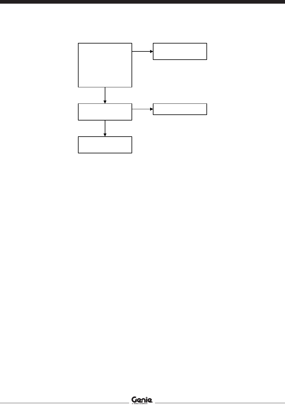
REV A
August 2005Section 5 • Troubleshooting Flow Charts
5 - 6 GR-8 • GR-12 • GR-15 Part No. 72965
Chart 3
All Functions
Inoperative,
Power Unit
Starts and
Runs
Be sure the circuit
breaker and fuses
are not tripped or
blown.
Be sure the
batteries are fully
charged and
properly connected.
Be sure the
hydraulic tank is
filled to the correct
level.
Check for a positive
connection between
electric motor and pump
on the hydraulic power
unit M5. Visually inspect
the pump splined shaft
for damage.
bad
Replace the pump OR
replace the motor.
good
Test the hydraulic pump.
(See Repair Section).
bad
good
Replace the pump.
Consult Genie Industries
Service Department.

REV A
August 2005
Section 5 • Troubleshooting Flow Charts
Part No. 72965 GR-8 • GR-12 • GR-15 5 - 7
Ground
Controls
Inoperative,
Platform
Controls
Operate
Normally
Be sure the circuit
breaker and fuses
are not tripped or
blown.
Be sure the
batteries are
properly connected.
Be sure the
batteries are fully
charged.
Chart 4
With key switch turned
to ground control and,
both Emergency Stop
buttons pulled out to the
ON
position, activate and
hold the platform
up/down toggle switch
TS66 in the
UP
position.
Check for continuity to
ground on the OR wire
at the center terminal on
TS66.
Replace contact for
ground controls at KS1.
continuity
Check for continuity to
ground on the OR wire
at the output terminal on
TS66.
Test or replace TS66
(See Repair Section).
continuity
Consult the Genie
Industries Service
Department.
Check if internal cam at
KS1 is activating the
ground control contact.
yes
no
Replace KS1.
no
continuity
no
continuity

REV A
August 2005Section 5 • Troubleshooting Flow Charts
5 - 8 GR-8 • GR-12 • GR-15 Part No. 72965
Chart 5
Platform
Controls
Inoperative,
Ground
Controls
Operate
Normally
Be sure the circuit
breaker and fuses
are not tripped or
blown.
Be sure the
batteries are
properly connected.
Be sure the
batteries are fully
charged.
With key switch turned
to platform control and
both Emergency Stop
buttons pulled out to the
ON
position, move the
lift/drive select switch
TS16 to the
LIFT
position. Press and hold
the function enable
switch SW5 and move
the joystick controller
JC3 in the direction
indicated by the blue
arrow. Check for
continuity to ground on
the BK wire at the
platform control contact
on key switch KS1.
no
continuity
Check if internal cam at
KS1 is activating the
platform control contact.
continuity
Consult Genie Industries
Service Department.
no
continuity
Repair open in circuit
from terminal #6 on
TS16 to BK wire at
platform control contact
on KS1.
no
Replace KS1.
yes
Replace contact for
platform control at KS1

REV A
August 2005
Section 5 • Troubleshooting Flow Charts
Part No. 72965 GR-8 • GR-12 • GR-15 5 - 9
Platform Up
Function
Inoperative
Be sure all other
functions operate
normally.
Be sure the circuit
breaker and fuses
are not tripped or
blown.
Be sure the
batteries are fully
charged and
properly connected.
Chart 6
With key switch turned
to platform control and
both Emergency Stop
buttons pulled out to the
ON
position, move the
lift/drive select switch
TS16 to the
LIFT
position. Press and hold
the function enable
switch SW5 and move
the joystick controller
JC3 in the direction
indicated by the blue
arrow. Check voltage on
YL/BK wire at platform
up solenoid valve Y8.
0V
Repair open in circuit
from Y8 through
platform up disable relay
CR31 (if equipped) and
platform up relay CR52
to voltage divider U14.
24V
Disconnect the wires
from Y8 and measure
the coil resistance (See
Repair Section).
0 or
infinite
ohms
Replace coil on Y8.
23 to 26 ohms
Repair or replace the
plaftorm up directional
valve cartrige (item D or
F) OR consult Genie
Industries Service
Department.

REV A
August 2005Section 5 • Troubleshooting Flow Charts
5 - 10 GR-8 • GR-12 • GR-15 Part No. 72965
Chart 7
Platform
Down
Function
Inoperative
Be sure all other
functions operate
normally.
Be sure the circuit
breaker and fuses
are not tripped or
blown.
Be sure the
batteries are fully
charged and
properly connected.
With key switch turned
to platform controls and
both Emergency Stop
buttons pulled out to the
ON
position, move the
lift/drive select switch
TS16 to the
LIFT
position. Press and hold
the function enable
switch SW5 and move
the joystick controller
JC3 in the direction
indicated by the yellow
arrow. Check voltage on
YL wire at platform
down solenoid valve Y7.
0V
Repair open in circuit
from Y7 through
platform down control
relay CR51 to voltage
divider U14.
24V
Disconnect the wires
from Y7 and measure
the coil resistance See
Repair Section.
0 or
infinite
ohms
Replace coil on Y7.
23 to 26 ohms
Repair or replace the
plaftorm up directional
valve cartrige (item K)
OR consult Genie
Industries Service
Department.

REV A
August 2005
Section 5 • Troubleshooting Flow Charts
Part No. 72965 GR-8 • GR-12 • GR-15 5 - 11
Chart 8
Steer Left
Function
Inoperative
Be sure all other
functions operate
normally.
Be sure the circuit
breaker and fuses
are not tripped or
blown.
Be sure the
batteries are fully
charged and
properly connected.
With key switch turned
to platform controls and
both Emergency Stop
buttons pulled out to the
ON
position, move the
lift/drive select switch
TS16 to the drive
position. Press and hold
the function enable
switch SW5. Press the
thumb rocker switch
SW5 on top of the
joystick controller JC3 in
the direction indicated
by the blue arrow.
Check voltage on OR
wire at steer left
0V
Repair open in circuit
from Y4 through steer
left control relay CR53
to voltage divider U14.
24V
Disconnect the wires
from Y4 and measure
the coil resistance See
Repair Section.
0 or
infinite
ohms
Replace coil on Y4.
23 to 26 ohms
Repair or replace the
plaftorm up directional
valve cartrige (item C, G
or E) OR consult Genie
Industries Service
Department.

REV A
August 2005Section 5 • Troubleshooting Flow Charts
5 - 12 GR-8 • GR-12 • GR-15 Part No. 72965
Chart 9
Steer Right
Function
Inoperative
Be sure all other
functions operate
normally.
Be sure the circuit
breaker and fuses
are not tripped or
blown.
Be sure the
batteries are fully
charged and
properly connected.
With key switch turned
to platform controls and
both Emergency Stop
buttons pulled out to the
ON
position, move the
lift/drive select switch
TS16 to the drive
position. Press and hold
the function enable
switch SW5. Press the
thumb rocker switch
SW5 on top of the
joystick controller JC3 in
the direction indicated
by the blue arrow.
Check voltage on
OR/BK wire at steer
right solenoid valve Y3.
0V
Repair open in circuit
from Y3 through steer
left control relay CR54
to voltage divider U14.
24V
Disconnect the wires
from Y3 and measure
the coil resistance See
Repair Section.
0 or
infinite
ohms
Replace coil on Y3.
23 to 26 ohms
Repair or replace the
plaftorm up directional
valve cartrige (item C, G
or E) OR consult Genie
Industries Service
Department.

REV A
August 2005
Section 5 • Troubleshooting Flow Charts
Part No. 72965 GR-8 • GR-12 • GR-15 5 - 13
Chart 10
All Drive
Functions
Inoperative,
All Other
Functions
Operate
Normally
Be sure the circuit
breaker and fuses
are not tripped or
blown.
Be sure the
batteries are fully
charged and
properly connected.
power
unit runs
Test OR replace TS16,
(See Repair Section).
power unit
not runnig
Replace the platform
controls with a known
operating platform
controls. Activate the
drive function. Does the
drive function operate?
With key switch turned
to platform controls and
both Emergency Stop
buttons pulled out to the
ON position, move the
lift/drive select switch
TS16 to the drive
position. Press and hold
the function enable
switch SW5. Move the
joystick controller JC3 in
the drive forward, then
the drive reverse
direction. Check if the
hydraulic power unit is
running.
no
yes
Replace the platform
controls.
Consult the Genie
Industries Service
Department.

REV A
August 2005Section 5 • Troubleshooting Flow Charts
5 - 14 GR-8 • GR-12 • GR-15 Part No. 72965
Chart 10A
Brake
Release
Function
Inoperative
Be sure the circuit
breaker and fuses
are not tripped or
blown.
Be sure the
batteries are fully
charged and
properly connected.
Connect a 0 to 3000 PSI
(207 bar) pressure
gauge to the test port on
the function manifold
(item A). Activate drive
forward and record the
reading on the pressure
gauge.
wheels
turn
The machine is
functioning properly.
less than
2700 psi
Adjust the system
pressure relief valve
(item H) (See Repair
Section).
Chock the wheels at the
steer end of the
manchine. Raise the
non-steer end of the
machine and place
blocks under the chassis
for support.
After serial number
248:
Activate the brake
release valve (item I) on
the function manifold.
All models:
With key switch turned
to platform controls and
both Emergency Stop
buttons pulled out to the
ON
position, move the
lift/drive select switch
TS16 to the drive
position. Press and hold
the function enable
switch SW5. Move the
joystick controller JC3 in
the drive forward
direction, then release it.
Turn each wheel by
hand. Each wheel
should turn freely
without much effort.
wheels do
not turn
2700
psi or
more
Remove both brake
hoses from the brake
fittings and place them
in a suitable container.
Activate drive forward
and check for hydraulic
fluid from each hose.
hydraulic oil
Repair OR replace the
brakes
.
no
hydraulic
oil
Consult the Genie
Industries Service
Department.

REV A
August 2005
Section 5 • Troubleshooting Flow Charts
Part No. 72965 GR-8 • GR-12 • GR-15 5 - 15
Chart 11
Drive
Forward
Function
Inoperative
Be sure all other
functions operate
normally.
Be sure the circuit
breaker and fuses
are not tripped or
blown.
Be sure the
batteries are fully
charged and
properly connected.
With key switch turned
to platform controls and
both Emergency Stop
buttons pulled out to the
ON
position, move the
lift/drive select switch
TS16 to the drive
position. Press and hold
the function enable
switch SW5. Move the
joystick controller JC3 in
the drive forward
direction. Check voltage
on BN/BK wire at drive
forward directional valve
coil Y6.
0V
Repair open in circuit
from Y6 through steer
left control relay CR56
to voltage divider U14.
24 Volts
Disconnect the wires
from Y6 and measure
the coil resistance See
Repair Section.
0 or
infinite
ohms
Replace coil Y6.
22 to 24 ohms
Repair or replace the
drive forward directional
valve cartrige (item C or
E) OR consult Genie
Industries Service
Department.

REV A
August 2005Section 5 • Troubleshooting Flow Charts
5 - 16 GR-8 • GR-12 • GR-15 Part No. 72965
Chart 12
Drive
Reverse
Function
Inoperative
Be sure all other
functions operate
normally.
Be sure the circuit
breaker and fuses
are not tripped or
blown.
Be sure the
batteries are fully
charged and
properly connected.
With key switch turned
to platform controls and
both Emergency Stop
buttons pulled out to the
ON
position, move the
lift/drive select switch
TS16 to the drive
position. Press and hold
the function enable
switch SW5. Move the
joystick controller JC3 in
the drive forward
direction. Check voltage
on BN wire at drive
forward directional valve
coil Y5.
0V
Repair open in circuit
from Y5 through steer
left control relay CR55
to voltage divider U14.
24 Volts
Disconnect the wires
from Y5 and measure
the coil resistance See
Repair Section.
0 or
infinite
ohms
Replace coil Y5.
22 to 24 ohms
Repair or replace the
drive forward directional
valve cartrige (item C or
E) OR consult Genie
Industries Service
Department.

REV A
August 2005
Section 5 • Troubleshooting Flow Charts
Part No. 72965 GR-8 • GR-12 • GR-15 5 - 17
Chart 13
Machine Will
Not Drive At
Full Speed
Be sure all other
functions operate
normally.
Be sure the circuit
breaker and fuses
are not tripped or
blown.
Be sure the
batteries are fully
charged and
properly connected.
With key switch turned
to platform controls and
both Emergency Stop
buttons pulled out to the
ON
position, move the
lift/drive select switch
TS16 to the drive
position. Activate the
drive speed select
Before serial number
248:
button BN25, OR
After serial number
247:
toggle switch TS5,
until all three drive
speed indicator lights
are on.. Press and hold
the function enable
switch SW5. Move the
joystick controller JC3 in
the full drive forward
direction. Check voltage
on BL wire at terminal
#3 on motor controller
U6.
Replace motor controller
U6.
less than
3.18V
Replace drive speed
select printed circuit
board U29.
3.18V

REV A
August 2005Section 5 • Troubleshooting Flow Charts
5 - 18 GR-8 • GR-12 • GR-15 Part No. 72965
Chart 14
Machine
Drives At
Full Speed
With
Platform
Raised
Be sure the circuit
breaker and fuses
are not tripped or
blown.
Be sure the
batteries are fully
charged and
properly connected.
more than
1.23V
1.23V
Test resistors R11,
R11A, and R13 for
proper resistance.
Replace motor controller
U6.
ok
Replace drive speed
select printed circuit
board U29 OR replace
JC3 OR consult Genie
Industries Service
Department.
bad
Replace faulty resistor
and repeat voltage test
on BL wire at terminal
#3 on U6.
Test limit switch LS5 for
proper adjustment and
operation.
bad
Replace LS5.
ok
Raise the steer end of
the machine and place
blocks under the drive
chassis for support.
With key switch turned
to platform controls and
both Emergency Stop
buttons pulled out to the
ON
position, raise the
platform approximately 2
feet. Move the lift/drive
select toggle switch
TS16 to the drive
position. Activate the
drive speed select
Before serial number
248:
button BN25, OR
After serial number
247:
toggle switch TS5,
until all three drive
speed indicator lights
are on. Press and hold
the function enable
switch SW5. Move the
joystick controller JC3 in
the full drive forward
direction. Check voltage
on BL wire at terminal
#3 on the motor
controller U6.

Section 6 • SchematicsAugust 2005
Part No. 72965 GS-8 • GR-12 • GR-15 6 - 1
Schematics
Observe and Obey:
Troubleshooting and repair procedures shall be
completed by a person trained and qualified on
the repair of this machine.
Immediately tag and remove from service a
damaged or malfunctioning machine.
Repair any machine damage or malfunction
before operating the machine.
Before Troubleshooting:
Read, understand and obey the safety rules
and operating instructions in the appropriate
operator's manual on your machine.
Be sure that all necessary tools and test
equipment are available and ready for use.
About This Section
There are two groups of schematics in this section.
An illustration legend precedes each group of
drawings.
Electrical Schematics
Electrocution hazard. Contact with
electrically charged circuits could
result in death or serious injury.
Remove all rings, watches and
other jewelry.
Hydraulic Schematics
Bodily injury hazard. Spraying
hydraulic oil can penetrate and
burn skin. Loosen hydraulic
connections very slowly to allow
the oil pressure to dissipate
gradually. Do not allow oil to squirt
or spray.
General Repair Process
Malfunction
discovered
Identify
symptoms
Troubleshoot
Perform
repair
Return to
service
problem
solved
problem
still exists
Inspect
and test

Section 6 • Schematics August 2005
REV B
6 - 2 GS-8 • GR-12 • GR-15 Part No. 72965
Ground Controls Layout and Electrical Component Legend
K5
K3
K1
K4
K2
K12
1
8
7
6
5
4
3
2
1
9
8
7
6
5
4
3
2
10
11
12
c d e f g k ij
CR51
PLATFORM
DOWN
CR52
PLATFORM
UP
CR53
STEER
LEFT
CR54
STEER
RIGHT
CR55
DRIVE
REVERSE
CR56
DRIVE
FORWARD
ON
OFF
12
K1
K2
K4
K3
K5
K6
1
9
8
7
6
5
4
3
2
1
9
8
7
6
5
4
3
2
10
11
12
13
14
b c d e f g h ia
CR51
PLATFORM
DOWN
CR52
PLATFORM
UP
CR53
STEER
LEFT
CR54
STEER
RIGHT
CR55
DRIVE
REVERSE
CR56
DRIVE
FORWARD
Ground Controls Circuit Board
(after serial number GR02-1799)
Ground Controls Circuit Board
(before serial number GR02-1800)
Circuit Board Legend
a 9-pin terminal strip W4
b DIP switch
c relay - platform up CR52
d relay - steer right CR54
e relay - steer left CR53
f relay - drive reverse CR55
g relay - drive forward CR56
h 14-pin terminal strip W3
i relay - platform down CR51
j 8-pin terminal strip W4
k 12-pin terminal strip W3
ELECTRICAL COMPONENT LEGEND
Item Description
B5 Battery
BN5 Horn button
C3 Capacitor, 1.0 uF
CB2 Circuit breaker, 7A
Control relay CR
CR51 = Platform down
CR52 = Platform up
CR53 = Steer left
CR54 = Steer right
CR55 = Drive reverse
CR56 = Drive forward
CR57 = Tilt alarm
D6 AC power outlet
EN4 Enclosure, junction box
F8 Fuse, 275A
FB1 Flashing beacons
G G6 = Hour meter
GND Ground
Horn or alarm H
H1 = Horn
H2 = Automotive-style horn (option)
H5 = Multifunction alarm
JC3 Joystick controller
KS1 Key switch
Limit switch LS
LS1 = Platform extend
LS5 = Platform up (option)
LS16 = Drive cut out
M5 Hydraulic power unit
NC Normally closed
NCHO Normally closed held open
NOHC Normally open held closed
Power switch P
P1 = Emergency Stop button at ground controls
P2 = Emergency Stop button at platform controls
Quick disconnect QD
QD1 = Battery quick disconnect
QD5 = Battery charger
QD16 = AC box to platform control box
Resistor R
R8 = 2500 ohms, lift speed
R9 = 3000 ohms, steer speed
R10 = 250 ohms, motor controller
R11 = 1000 ohms, drive
R12 = 0 to 2000 ohms, drive speed
R13 = 1800 ohms, platform raised drive speed
Switch SW
SW5 = Function enable
SW6 = Steer left/right
S7 Tilt level sensor
Toggle switch TS
TS16 = Lift/drive select
TS66 = Platform up/down
Electronic component U
U6 = Motor controller
U10 = Machine functions printed circuit board
U11 = Battery charger
U14 = Voltage divider
U29 = Drive speed select printed circuit board
U31 = 1000W charger/inverter
U32 = Inverter remote panel
Valve coil Y
Y3 = Steer right
Y4 = Steer left
Y5 = Drive reverse
Y6 = Drive forward
Y7 = Platform down
Y8 = Platform up

Section 6 • SchematicsAugust 2005
REV B
Part No. 72965 GS-8 • GR-12 • GR-15 6 - 3
Electrical Symbols and Wire Color Legends
-
+
CB2
N.C.H.O.
N.C.
U9
7
3
6
4
5
7
3
1
6
4
2
5
LEVEL SENSOR
CIRCUIT BOARD
M5
Circuits crossing
no connection
Diode
Circuit connection
Hour meter
Limit switch
Toggle switch
Switch or button
Connector Emergency Stop button
Circuit breaker
Motor
Level sensor
Battery charger
Battery
Fuse
Control relay
Solenoid valve
Capacitor
Horn or alarm
Flashing beacon
WIRE COLOR LEGEND
Color Description
BK Black
BL Blue
BN Brown
GN Green
sLT BL Light Blue
OR Orange
RD Red
WH White
YL Yellow

Section 6 • Schematics January 2007
REV C
6 - 4 GS-8 • GR-12 • GR-15 Part No. 72965
Electrical Schematic
ANSI Models (before serial number GR02-1800)
Part 1 of 2
ES0067H
RD/BK-5
WH/BK-6
BL-8
GR/YL-4
BN-4
RD-3
LT BL-1
OR-7
1800
R13
RD/BK
YL
BL
GR/ YL
BN
RD
WH
OR
BK
WH
LS5
275A
F8
B+
A2
B
M
3
1
BK
(+)
QD1
QD5
H1
TILT LEVEL SENSOR
RD
WH
7A
CB2
PLATFORM
GROUND
KS1
BN
RD
GN/YL
RD
OR
RD
PLATFORM
(DOWN)
PLATFORM
YL
OR
10
OR
RD
BL
BL/WH
BK
PLATFORM
GROUND
WH
BK
13
1
14
9
TS66
RD/BK
BL
12
WH
(OPTION)
INVERTER
CHARGER
1000 W
PANEL
REMOTE
INVERTER
P1
QD1
(
-
)
M5
+
-
-
-
+
+
+
f
1.0
-
-
S7
250
BN
GN/YL
TILT ALARM
GND
GND
GND
BL
9
8
7
6
5
4
3
2
1
BK
11
-
H1
S7
CR57
R10
D5
OR
BL
BL
RD
GN/YL
RD
RD
BK
GN/YL
GN/YL
RD
BL
GN/YL
BK
RD
OR
GN/YL
GN/YL
RD
U11
U32
U31
BK
GN/YL
B5
U6
5
FB1
W3
U14
C3
N.O.H.C.
N.C.
GN/YL
OR
24V DC
24V DC
12V DC
BK-2
BK
BN
UP
DOWN
RD/WH
GROUND
CONTROLLER
-NOTE-
MACHINE SHOWN
IN THE STOWED
POSITION WITH
THE POWER OFF

Section 6 • SchematicsJanuary 2007
REV C
Part No. 72965 GS-8 • GR-12 • GR-15 6 - 5
Electrical Schematic
ANSI Models (before serial number GR02-1800)
Part 2 of 2
ES0067H
3000
2500
CR52
FORWARD
DRIVE
RIGHT
STEER
STEER
LEFT
UP
PLATFORM
DOWN
PLATFORM
CR51
N.O.
N.C.
CR53
N.O.
CR54
N.O.
CR55
N.C.
CR56
N.C.
REVERSE
DRIVE
R8
R9
7
6
5
8
1
2
3
4
8
1
2
3
4
6
5
7
8
3
4
7
6
5
8
3
4
6
5
7
8
1
2
3
4
7
6
5
7
5
8
1
3
BL
GN/YL
EN4
WH-2
BL-6
BK-5
BN-4
RD-3
OR-7
FWD
REV
YL
RD
YL
B
RD
GN/BK
L
C
R
OR
A
8
OR
SW5
GN/YL
2
BN
RD
5
3
4
YL
1
20k
YL
1
5
2
7
BL
4
BL
P2
YL
6
GN/BK
BN5
H2
JC3
TS16
QD16
U24
1000
R11
1000
R11A
0-2000
R12
YL
BL
BK
GN/BK
RD
OR
RD
RD
GN/YL
LS16
N.O.H.C.
N.O.H.C.
LS1
BL
BL BL
BL
U29
D6
SW6
*N16
HOURMETER
+
-
DRIVE/
PLATFORM UP
STEER RIGHT
DRIVE REVERSE
DRIVE FORWARD
STEER LEFT
PLATFORM DOWN
DECENT/DRIVE/
STEER ALARM
Y7
Y8
Y4
Y3
Y5
Y6
H5
G6
YL
YL/BK
BL
BN/BK
BN
OR/BK
OR
GN/YL
GN/YL
H5
YL/BK
G6
1
2
3
4
5
6
8
W4
GND
JUNCTION BOX
PLATFORM CONTROLLER
RELAY BOARD
- NOTE -
MACHINE SHOWN
IN THE STOWED
POSITION WITH
THE POWER OFF

Section 6 • Schematics January 2007
REV C
6 - 6 GS-8 • GR-12 • GR-15 Part No. 72965
Electrical Schematic
ANSI and CSA Models (from serial number GR02-1800 to GR03-2407)
Part 1 of 2
ES0083B
RD/BK-5
WH/BK-6
BL-8
BN-4
RD-3
OR-7
RD/BK
YL
BL
BK-2
BK
BN
RD
LT BL-1
WH
OR
BK
WH
LS5
275A
F8
B+
A2
B
M
3
1
BK
(+)
QD1
QD5
7A
CB2
PLATFORM
GROUND
KS1
BN
RD
BN
RD
OR
RD
PLATFORM
UP
DOWN
PLATFORM
YL
OR
10
OR
RD
BL
BN
BL/WH
BK
PLATFORM
GROUND
WH
BK
TS66
RD/BK
BL
12
WH
(OPTION)
INVERTER
CHARGER
1000 W
PANEL
REMOTE
INVERTER
P1
QD1
(
-
)
M5
+
-
-
-
+
+
+
f
1.0
-
-
250
10A FUSE
GND
GND
BL
9
8
7
6
5
4
3
2
1
BK
11
-
R10
D5
OR
BL
BL
RD
GN/YL
RD
RD
BK
GN/YL
GN/YL
RD
BL
GN/YL
BK
GN/YL
U11
U32
U31
BK
B5
U6
GROUND
CONTROLLER
FB1
W3
U14
C3
N.O.H.C.
GN/YL
BK
OR
BK
24V DC
24V DC
12V DC
GN/YL GN/YL-4
GND
TILT LEVEL
SENSOR
RD
WH
S7
BN
BN
S7
RD
13
WH
14
WH
- NOTE -
MACHINE SHOWN
IN THE STOWED
POSITION WITH
THEPOWEROFF

Section 6 • SchematicsJanuary 2007
REV C
Part No. 72965 GS-8 • GR-12 • GR-15 6 - 7
Electrical Schematic
ANSI and CSA Models (from serial number GR02-1800 to GR03-2407)
Part 2 of 2
ES0083B
1800
RELAY BOARD
H1
HOURMETER
+
-
DRIVE/
PLATFORM UP
STEER RIGHT
DRIVE
REVERSE
DRIVE
FORWARD
STEER LEFT
PLATFORM
DOWN
TILT ALARM
DECENT/DRIVE/
STEER ALARM
Y7
Y8
Y4
Y3
Y5
Y6
H5
G6
H1
YL
YL/BK
BL
BN/BK
BN
OR/BK
OR
GN/YL
GN/YL
GN/YL
H2
G6
BL
GN/YL
JUNCTION
BOX
WH-2
BL-6
BK-5
BN-4
RD-3
OR-7
FWD
REV
YL
RD
YL
B
RD
GN/BK
L
C
R
OR
A
8
OR
SW5
GN/YL
2
BN
RD
5
3
4
YL
1
20k
YL
1
5
2
7
BL
4
BL
P2
YL
6
GN/BK
BN5
H2
JC3
LS16
N.O.H.C.
N.O.H.C.
LS1
PLATFORM CONTROLLER
TS16
QD16
U24
1000
R11
1000
R11A
0-2000
R12
YL
BL
BK
GN/BK
RD
OR
RD
RD
GN/YL
BL
BL BL
BL
U29
D6
SW6
*N16
BN
1
2
3
4
5
6
7
3000
2500
CR52
FORWARD
DRIVE
RIGHT
STEER
STEER
LEFT
UP
PLATFORM
DOWN
PLATFORM
CR51
N.O.
N.C.
CR53
N.O.
CR54
N.O.
CR55
N.C.
CR56
N.C.
REVERSE
DRIVE
W4
R8
U10
R9
7
6
5
8
1
2
3
4
8
1
2
3
4
6
5
7
8
3
4
7
6
5
8
3
4
6
5
7
8
1
2
3
4
7
6
5
7
5
8
1
3
9 8
- NOTE -
MACHINE SHOWN
IN THE STOWED
POSITION WITH
THE POWER OFF
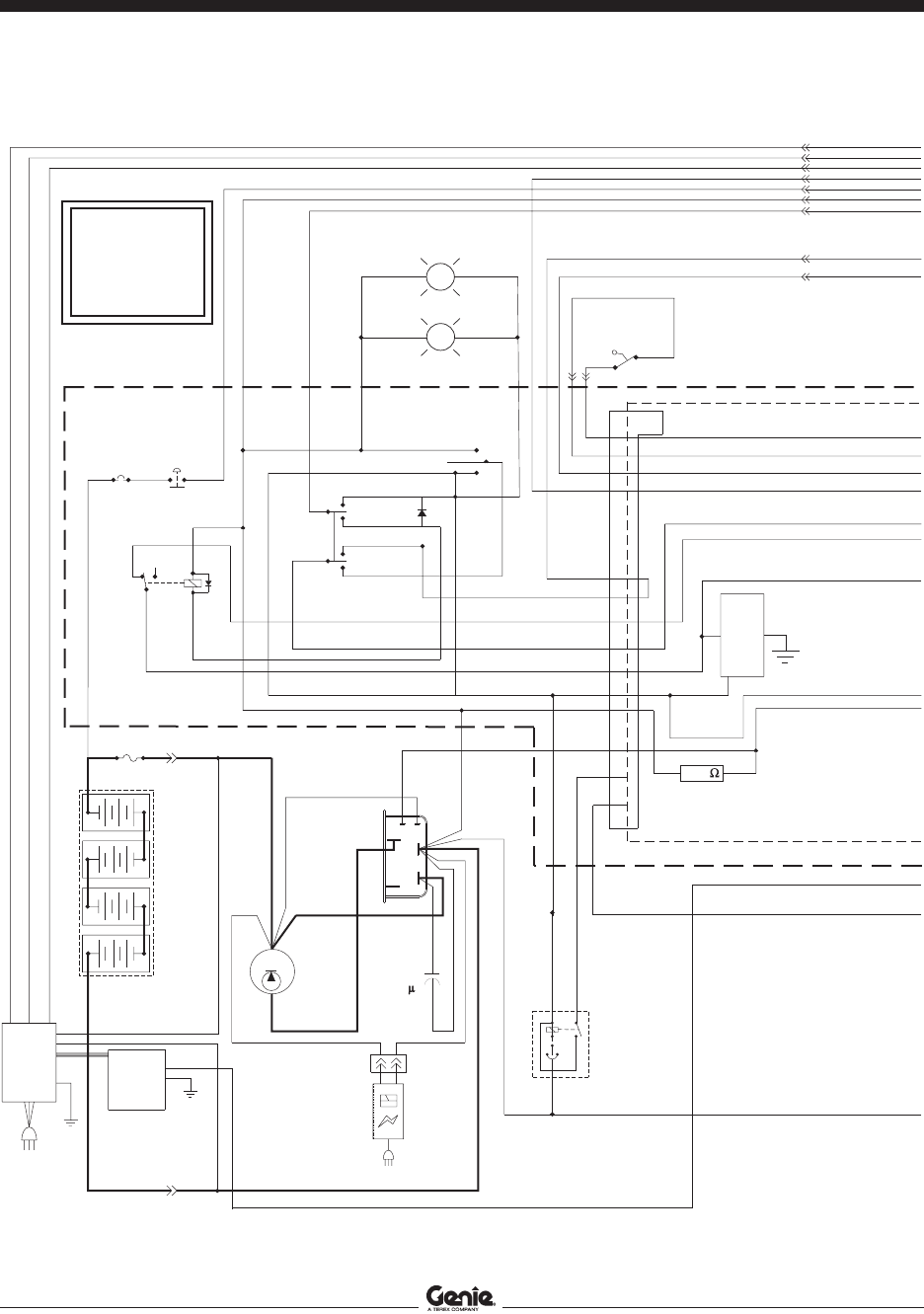
Section 6 • Schematics January 2007
REV B
6 - 8 GS-8 • GR-12 • GR-15 Part No. 72965
Electrical Schematic
ANSI and CSA Models (from serial number GR03-2408 to GR03-2432)
Part 1 of 2
ES0083C
RD/BK-5
WH/BK-6
BL-8
BN-4
RD-3
OR-7
RD/BK
YL
BL
BK-2
BK
BN
RD
LT BL-1
WH
OR
BK
WH
LS5
275A
F8
B+
A2
B
M
3
1
BK
(+)
QD1
QD5
7A
CB2
PLATFORM
GROUND
KS1
BN
RD
BN
RD
OR
RD
UP
DOWN
PLATFORM
YL
OR
10
OR
RD
BL
BN
BL/WH
BK
PLATFORM
GROUND
WH
BK
TS66
RD/BK
BL
12
WH
(OPTION)
INVERTER
CHARGER
1000 W
PANEL
REMOTE
INVERTER
P1
QD1
(
-
)
M5
+
-
-
-
+
+
+
f
1.0
-
-
250
10A FUSE
GND
GND
BL
9
8
7
6
5
4
3
2
1
BK
11
-
R10
D5
OR
BL
BL
RD
GN/YL
RD
RD
BK
GN/YL
GN/YL
RD
BL
GN/YL
BK
GN/YL
U11
U32
U31
BK
B5
U6
GROUND
CONTROLLER
FB1
W3
U14
C3
N.O.H.C.
GN/YL
BK
OR
BK
24V DC
24V DC
12V DC
GN/YL GN/YL-4
GND
TILT LEVEL
SENSOR
RD
WH
S7
BN
BN
S7
RD
13
WH
14
WH
PLATFORM
GROUND
BL
- NOTE -
MACHINE SHOWN
IN THE STOWED
POSITION WITH
THEPOWEROFF

Section 6 • SchematicsJanuary 2007
REV B
Part No. 72965 GS-8 • GR-12 • GR-15 6 - 9
Electrical Schematic
ANSI and CSA Models (from serial number GR03-2408 to GR03-2432)
Part 2 of 2
ES0083C
1800
RELAY BOARD
H1
HOURMETER
+
-
DRIVE/
PLATFORM UP
STEER RIGHT
DRIVE
REVERSE
DRIVE
FORWARD
STEER LEFT
PLATFORM
DOWN
TILT ALARM
DECENT/DRIVE/
STEER ALARM
Y7
Y8
Y4
Y3
Y5
Y6
H5
G6
H1
YL
YL/BK
BL
BN/BK
BN
OR/BK
OR
GN/YL
GN/YL
GN/YL
H2
G6
BL
GN/YL
EN4
WH-2
BL-6
BK-5
BN-4
RD-3
OR-7
FWD
REV
YL
RD
YL
B
RD
GN/BK
L
C
R
OR
A
8
OR
SW5
GN/YL
2
BN
RD
5
3
4
YL
1
20k
YL
1
5
2
7
BL
4
BL
P2
YL
6
GN/BK
BN5
H2
JC3
LS16
N.O.H.C.
N.O.H.C.
LS1
PLATFORM CONTROLLER
TS16
QD16
U24
1000
R11
1000
R11A
0-2000
R12
YL
BL
BK
GN/BK
RD
OR
RD
RD
GN/YL
BL
BL BL
BL
U29
D6
SW6
*N16
BN
1
2
3
4
5
6
7
3000
2500
CR52
FORWARD
DRIVE
RIGHT
STEER
STEER
LEFT
UP
PLATFORM
DOWN
PLATFORM
CR51
N.O.
N.C.
CR53
N.O.
CR54
N.O.
CR55
N.C.
CR56
N.C.
REVERSE
DRIVE
W4
R8
U10
R9
7
6
5
8
1
2
3
4
8
1
2
3
4
6
5
7
8
3
4
7
6
5
8
3
4
6
5
7
8
1
2
3
4
7
6
5
7
5
8
1
3
9 8
- NOTE -
MACHINE SHOWN
IN THE STOWED
POSITION WITH
THE POWER OFF

Section 6 • Schematics January 2007
REV B
6 - 10 GS-8 • GR-12 • GR-15 Part No. 72965
Electrical Schematic
ANSI and CSA Models (after serial number GR03-2432)
Part 1 of 2
ES0083D
RD/BK-5
WH/BK-6
BL-8
BN-4
RD-3
OR-7
RD/BK
YL
BL
BK-2
BK
BN
RD
LT BL-1
WH
OR
BK
WH
LS5
275A
F8
B+
A2
B
M
3
1
BK
(+)
QD1
QD5
7A
CB2
PLATFORM
GROUND
KS1
BN
RD
BN
RD
OR
RD
UP
DOWN
PLATFORM
YL
OR
10
OR
RD
BL
BN
BL/WH
BK
PLATFORM
GROUND
WH
BK
TS66
RD/BK
BL
12
WH
(OPTION)
INVERTER
CHARGER
1000 W
PANEL
REMOTE
INVERTER
P1
QD1
(
-
)
M5
+
-
-
-
+
+
+
f
1.0
-
-
250
10A FUSE
GND
GND
BL
9
8
7
6
5
4
3
2
1
BK
11
-
R10
D5
OR
BL
BL
RD
GN/YL
RD
RD
BK
GN/YL
GN/YL
RD
BL
GN/YL
BK
GN/YL
U11
U32
U31
BK
B5
U6
GROUND
CONTROLLS
FB1
W3
U14
C3
N.O.H.C.
GN/YL
BK
OR
BK
24V DC
24V DC
12V DC
GN/YL GN/YL-4
GND
TILT LEVEL
SENSOR
RD
WH
S7
BN
BN
S7
13
WH
14
WH
PLATFORM
GROUND
BL
- NOTE -
MACHINE SHOWN
IN THE STOWED
POSITION WITH
THEPOWEROFF

Section 6 • SchematicsJanuary 2007
REV B
Part No. 72965 GS-8 • GR-12 • GR-15 6 - 11
Electrical Schematic
ANSI and CSA Models (after serial number GR03-2432)
Part 2 of 2
ES0083D
1800
RELAY BOARD
H1
HOURMETER
+
-
DRIVE/
PLATFORM UP
STEER RIGHT
DRIVE
REVERSE
DRIVE
FORWARD
STEER LEFT
PLATFORM
DOWN
TILT ALARM
DECENT/DRIVE/
STEER ALARM
Y7
Y8
Y4
Y3
Y5
Y6
H5
G6
H1
YL
YL/BK
BL
BN/BK
BN
OR/BK
OR
GN/YL
GN/YL
GN/YL
H2
G6
BL
GN/YL
JUNCTION BOX
WH-2
BL-6
BK-5
BN-4
RD-3
OR-7
FWD
REV
YL
RD
YL
B
RD
GN/BK
L
C
R
OR
A
8
OR
SW5
GN/YL
2
BN
RD
5
3
4
YL
1
20k
YL
1
5
2
7
BL
4
BL
YL
6
GN/BK
BN5
H2
JC3
LS16
N.O.H.C.
N.O.H.C.
LS1
PLATFORM CONTROLLS
TS16
QD16
U24
1000
R11
1000
R11A
0-2000
R12
YL
BL
BK
GN/BK
RD
OR
RD
RD
GN/YL
BL
BL BL
BL
U29
D6
SW6
*N16
BN
1
2
3
4
5
6
7
3000
2500
CR52
FORWARD
DRIVE
RIGHT
STEER
STEER
LEFT
UP
PLATFORM
DOWN
PLATFORM
CR51
N.O.
N.C.
CR53
N.O.
CR54
N.O.
CR55
N.C.
CR56
N.C.
REVERSE
DRIVE
W4
R8
U10
R9
7
6
5
8
1
2
3
4
8
1
2
3
4
6
5
7
8
3
4
7
6
5
8
3
4
6
5
7
8
1
2
3
4
7
6
5
7
5
8
1
3
9 8
- NOTE -
MACHINE SHOWN
IN THE STOWED
POSITION WITH
THE POWER OFF
P2

Section 6 • Schematics January 2007
REV C
6 - 12 GS-8 • GR-12 • GR-15 Part No. 72965
Electrical Schematic
CE Models (before serial number GR02-1800)
Part 1 of 2
ES0068J
RD/BK-5
WH/BK-6
BL-8
GR/YL-4
BN-4
RD-3
LT BL-1
OR-7
1800
R13
RD/BK
YL
BL
GR/ YL
BN
RD
WH
OR
BK
WH
LS5
275A
F8
B+
A2
B
M
3
1
BK
(+)
QD1
QD5
LEVEL SENSOR
7A
CB2
KS1
BN
RD
GN/YL
RD
OR
RD
PLATFORM
PLATFORM
YL
OR
10
OR
RD
BL
BL/WH
BK
PLATFORM
GROUND
WH
BK
TS66
RD/BK
BL
12
WH
(OPTION)
INVERTER
CHARGER
1000 W
PANEL
REMOTE
INVERTER
P1
QD1
(
-
)
M5
+
-
-
-
+
+
+
f
1.0
-
-
250
TILT ALARM
GND
GND
GND
BL
9
8
7
6
5
4
3
2
1
BK
11
-
R10
D5
OR
BL
BL
RD
GN/YL
RD
RD
BK
GN/YL
GN/YL
RD
BL
GN/YL
BK
GN/YL
U11
U32
U31
BK
B5
U6
FB1
W3
U14
C3
N.O.H.C.
GN/YL
OR
24V DC
24V DC
12V DC
BK-2
BK
BN
UP
DOWN
RD/WH
GROUND
CONTROLLER
RD
WH
13
1
14
9
BN
BN
H1
S7
13
1
14
9
CR57
RD
OR
GN/YL
RD
RD
GN/YL
GN/YL
5
5
N.C.
PLATFORM
GROUND
H1S7
YL/BK
YL/BK
- NOTE -
MACHINE SHOWN
IN THE STOWED
POSITION WITH
THE POWER OFF
RELAY BOARD

Section 6 • SchematicsJanuary 2007
REV C
Part No. 72965 GS-8 • GR-12 • GR-15 6 - 13
Electrical Schematic
CE Models (before serial number GR02-1800)
Part 2 of 2
ES0068J
3000
2500
CR52
FORWARD
DRIVE
RIGHT
STEER
STEER
LEFT
UP
PLATFORM
DOWN
PLATFORM
CR51
N.O.
N.C.
CR53
N.O.
CR54
N.O.
CR55
N.C.
CR56
N.C.
REVERSE
DRIVE
R8
R9
7
6
5
8
1
2
3
4
8
1
2
3
4
6
5
7
8
3
4
7
6
5
8
3
4
6
5
7
8
1
2
3
4
7
6
5
7
5
8
1
3
HOURMETER
+
-
DRIVE/
PLATFORM UP
STEER RIGHT
DRIVE REVERSE
DRIVE FORWARD
STEER LEFT
PLATFORM DOWN
DECENT/DRIVE/
STEER ALARM
Y7
Y8
Y4
Y3
Y5
Y6
H5
G6
YL
YL/BK
BL
BN/BK
BN
OR/BK
OR
GN/YL
GN/YL
H5
YL/BK
G6
1
2
3
4
5
6
8
W4
- NOTE -
MACHINE SHOWN
IN THE STOWED
POSITION WITH
THE POWER OFF
YL/BK
YL/BK
RELAY BOARD
PLATFORM CONTROLLER
TS16
YL
YL
BL
OR
SW5
R12
0-2000W
JC3
YL
GN/YL
GN/BK
RD
BN
1000W
1000W
U24
20K
2
1
3
4
5
B
A
C
R
L
SW6
R11
R11A
2
1
4
5
6
7
8
YL
YL
OR
GN/BK
RD
REV
FWD
GN/YL
RD
U29
P2
BN5
GN/YL
RD
RD
GND
H2
RD
GN/BK
OR
BK
YL
BL
BL
BL
*N16
OR-7
RD-3
BN-4
BK-5
WH-2
BL-6
BL
BL
BL
BL
BL-8
WH/BK-6
RD/BK-5
OR-7
RD-3
BN-4
GR/YL-4
LT BL-1
BK-2
LS16
N.O.H.C.
LS1
N.O.H.C.
QD16
D6
JUNCTION BOX
EN4

Section 6 • Schematics January 2007
REV C
6 - 14 GS-8 • GR-12 • GR-15 Part No. 72965
Electrical Schematic
CE Models (from serial number GR02-1800 to GR03-2407)
Part 1 of 2
ES0083B
RD/BK-5
WH/BK-6
BL-8
BN-4
RD-3
OR-7
RD/BK
YL
BL
BK-2
BK
BN
RD
LT BL-1
WH
OR
BK
WH
LS5
275A
F8
B+
A2
B
M
3
1
BK
(+)
QD1
QD5
7A
CB2
PLATFORM
GROUND
KS1
BN
RD
BN
RD
OR
RD
PLATFORM
UP
DOWN
PLATFORM
YL
OR
10
OR
RD
BL
BN
BL/WH
BK
PLATFORM
GROUND
WH
BK
TS66
RD/BK
BL
12
WH
(OPTION)
INVERTER
CHARGER
1000 W
PANEL
REMOTE
INVERTER
P1
QD1
(
-
)
M5
+
-
-
-
+
+
+
f
1.0
-
-
250
10A FUSE
GND
GND
BL
9
8
7
6
5
4
3
2
1
BK
11
-
R10
D5
OR
BL
BL
RD
GN/YL
RD
RD
BK
GN/YL
GN/YL
RD
BL
GN/YL
BK
GN/YL
U11
U32
U31
BK
B5
U6
GROUND
CONTROLLER
FB1
W3
U14
C3
N.O.H.C.
GN/YL
BK
OR
BK
24V DC
24V DC
12V DC
GN/YL GN/YL-4
GND
TILT LEVEL
SENSOR
RD
WH
S7
BN
BN
S7
RD
13
WH
14
WH
- NOTE -
MACHINE SHOWN
IN THE STOWED
POSITION WITH
THEPOWEROFF
RELAY BOARD

Section 6 • SchematicsJanuary 2007
REV C
Part No. 72965 GS-8 • GR-12 • GR-15 6 - 15
Electrical Schematic
CE Models (from serial number GR02-1800 to GR03-2407)
Part 2 of 2
ES0083B
1800
H1
HOURMETER
+
-
DRIVE/
PLATFORM UP
STEER RIGHT
DRIVE
REVERSE
DRIVE
FORWARD
STEER LEFT
PLATFORM
DOWN
TILT ALARM
DECENT/DRIVE/
STEER ALARM
Y7
Y8
Y4
Y3
Y5
Y6
H5
G6
H1
YL
YL/BK
BL
BN/BK
BN
OR/BK
OR
GN/YL
GN/YL
GN/YL
H2
G6
BL
GN/YL
WH-2
BL-6
BK-5
BN-4
RD-3
OR-7
FWD
REV
YL
RD
YL
B
RD
GN/BK
L
C
R
OR
A
8
OR
SW5
GN/YL
2
BN
RD
5
3
4
YL
1
20k
YL
1
5
2
7
BL
4
BL
P2
YL
6
GN/BK
BN5
H2
JC3
LS16
N.O.H.C.
N.O.H.C.
LS1
PLATFORM CONTROLLER
TS16
QD16
U24
1000
R11
1000
R11A
0-2000
R12
YL
BL
BK
GN/BK
RD
OR
RD
RD
GN/YL
BL
BL BL
BL
U29
SW6
*N16
BN
1
2
3
4
5
6
7
3000
2500
CR52
FORWARD
DRIVE
RIGHT
STEER
STEER
LEFT
UP
PLATFORM
DOWN
PLATFORM
CR51
N.O.
N.C.
CR53
N.O.
CR54
N.O.
CR55
N.C.
CR56
N.C.
REVERSE
DRIVE
W4
R8
U10
R9
7
6
5
8
1
2
3
4
8
1
2
3
4
6
5
7
8
3
4
7
6
5
8
3
4
6
5
7
8
1
2
3
4
7
6
5
7
5
8
1
3
9 8
RD/BK-5
WH/BK-6
BL-8
BN-4
RD-3
OR-7
BK-2
LT BL-1
GN/YL-4
- NOTE -
MACHINE SHOWN
IN THE STOWED
POSITION WITH
THE POWER OFF
RELAY BOARD
EN4
D6
JUNCTION BOX

Section 6 • Schematics January 2007
REV B
6 - 16 GS-8 • GR-12 • GR-15 Part No. 72965
Electrical Schematic
CE Models (from serial number GR03-2408 to GR03-2432)
Part 1 of 2
ES0083C
RD/BK-5
WH/BK-6
BL-8
BN-4
RD-3
OR-7
RD/BK
YL
BL
BK-2
BK
BN
RD
LT BL-1
WH
OR
BK
WH
LS5
275A
F8
B+
A2
B
M
3
1
BK
(+)
QD1
QD5
7A
CB2
PLATFORM
GROUND
KS1
BN
RD
BN
RD
OR
RD
UP
DOWN
PLATFORM
YL
OR
10
OR
RD
BL
BN
BL/WH
BK
PLATFORM
GROUND
WH
BK
TS66
RD/BK
BL
12
WH
(OPTION)
INVERTER
CHARGER
1000 W
PANEL
REMOTE
INVERTER
P1
QD1
(
-
)
M5
+
-
-
-
+
+
+
f
1.0
-
-
250
10A FUSE
GND
GND
BL
9
8
7
6
5
4
3
2
1
BK
11
-
R10
D5
OR
BL
BL
RD
GN/YL
RD
RD
BK
GN/YL
GN/YL
RD
BL
GN/YL
BK
GN/YL
U11
U32
U31
BK
B5
U6
GROUND
CONTROLLER
FB1
W3
U14
C3
N.O.H.C.
GN/YL
BK
OR
BK
24V DC
24V DC
12V DC
GN/YL GN/YL-4
GND
RD
WH
S7
BN
BN
S7
RD
13
WH
14
WH
PLATFORM
GROUND
BL
- NOTE -
MACHINE SHOWN
IN THE STOWED
POSITION WITH
THEPOWEROFF
RELAY BOARD
LEVEL SENSOR

Section 6 • SchematicsJanuary 2007
REV B
Part No. 72965 GS-8 • GR-12 • GR-15 6 - 17
Electrical Schematic
CE Models (from serial number GR03-2408 to GR03-2432)
Part 2 of 2
ES0083C
1800
H1
HOURMETER
+
-
DRIVE/
PLATFORM UP
STEER RIGHT
DRIVE
REVERSE
DRIVE
FORWARD
STEER LEFT
PLATFORM
DOWN
TILT ALARM
ALARM
Y7
Y8
Y4
Y3
Y5
Y6
H5
G6
H1
YL
YL/BK
BL
BN/BK
BN
OR/BK
OR
GN/YL
GN/YL
GN/YL
H2
G6
BL
GN/YL
WH-2
BL-6
BK-5
BN-4
RD-3
OR-7
FWD
REV
YL
RD
YL
B
RD
GN/BK
L
C
R
OR
A
8
OR
SW5
GN/YL
2
BN
RD
5
3
4
YL
1
20k
YL
1
5
2
7
BL
4
BL
P2
YL
6
GN/BK
BN5
H2
JC3
LS16
N.O.H.C.
N.O.H.C.
LS1
PLATFORM CONTROLLER
TS16
QD16
U24
1000
R11
1000
R11A
0-2000
R12
YL
BL
BK
GN/BK
RD
OR
RD
RD
GN/YL
BL
BL BL
BL
U29
SW6
*N16
BN
1
2
3
4
5
6
7
3000
2500
CR52
FORWARD
DRIVE
RIGHT
STEER
STEER
LEFT
UP
PLATFORM
DOWN
PLATFORM
CR51
N.O.
N.C.
CR53
N.O.
CR54
N.O.
CR55
N.C.
CR56
N.C.
REVERSE
DRIVE
W4
R8
U10
R9
7
6
5
8
1
2
3
4
8
1
2
3
4
6
5
7
8
3
4
7
6
5
8
3
4
6
5
7
8
1
2
3
4
7
6
5
7
5
8
1
3
9 8
- NOTE -
MACHINE SHOWN
IN THE STOWED
POSITION WITH
THE POWER OFF
RD/BK-5
WH/BK-6
BL-8
BN-4
RD-3
OR-7
BK-2
LT BL-1
GN/YL-4
EN4
D6
JUNCTION BOX
RELAY BOARD

Section 6 • Schematics January 2007
REV B
6 - 18 GS-8 • GR-12 • GR-15 Part No. 72965
Electrical Schematic
CE Models (from serial number GR03-2433 to GR04-4000)
Part 1 of 2
ES0083D
RD/BK-5
WH/BK-6
BL-8
BN-4
RD-3
OR-7
RD/BK
YL
BL
BK-2
BK
BN
RD
LT BL-1
WH
OR
BK
WH
LS5
275A
F8
B+
A2
B
M
3
1
BK
(+)
QD1
QD5
7A
CB2
PLATFORM
GROUND
KS1
BN
RD
BN
RD
OR
RD
UP
DOWN
PLATFORM
YL
OR
10
OR
RD
BL
BN
BL/WH
BK
PLATFORM
GROUND
WH
BK
TS66
RD/BK
BL
12
WH
(OPTION)
INVERTER
CHARGER
1000 W
PANEL
REMOTE
INVERTER
P1
QD1
(
-
)
M5
+
-
-
-
+
+
+
f
1.0
-
-
250
10A FUSE
GND
GND
BL
9
8
7
6
5
4
3
2
1
BK
11
-
R10
D5
OR
BL
BL
RD
GN/YL
RD
RD
BK
GN/YL
GN/YL
RD
BL
GN/YL
BK
GN/YL
U11
U32
U31
BK
B5
U6
GROUND
CONTROLLS
FB1
W3
U14
C3
N.O.H.C.
GN/YL
BK
OR
BK
24V DC
24V DC
12V DC
GN/YL GN/YL-4
GND
TILT LEVEL
SENSOR
RD
WH
S7
BN
BN
S7
13
WH
14
WH
PLATFORM
GROUND
BL
-NOTE-
MACHINE SHOWN
IN THE STOWED
POSITION WITH
THE POWER OFF

Section 6 • SchematicsJanuary 2007
REV B
Part No. 72965 GS-8 • GR-12 • GR-15 6 - 19
Electrical Schematic
CE Models (from serial number GR03-2433 to GR04-4000)
Part 2 of 2
ES0083D
1800
RELAY BOARD
H1
HOURMETER
+
-
DRIVE/
PLATFORM UP
STEER RIGHT
DRIVE
REVERSE
DRIVE
FORWARD
STEER LEFT
PLATFORM
DOWN
TILT ALARM
DECENT/DRIVE/
STEER ALARM
Y7
Y8
Y4
Y3
Y5
Y6
H5
G6
H1
YL
YL/BK
BL
BN/BK
BN
OR/BK
OR
GN/YL
GN/YL
GN/YL
H2
G6
BL
GN/YL
JUNCTION BOX
WH-2
BL-6
BK-5
BN-4
RD-3
OR-7
FWD
REV
YL
RD
YL
B
RD
GN/BK
L
C
R
OR
A
8
OR
SW5
GN/YL
2
BN
RD
5
3
4
YL
1
20k
YL
1
5
2
7
BL
4
BL
YL
6
GN/BK
BN5
H2
JC3
LS16
N.O.H.C.
N.O.H.C.
LS1
PLATFORM CONTROLLS
TS16
QD16
U24
1000
R11
1000
R11A
0-2000
R12
YL
BL
BK
GN/BK
RD
OR
RD
RD
GN/YL
BL
BL BL
BL
U29
D6
SW6
*N16
BN
1
2
3
4
5
6
7
3000
2500
CR52
FORWARD
DRIVE
RIGHT
STEER
STEER
LEFT
UP
PLATFORM
DOWN
PLATFORM
CR51
N.O.
N.C.
CR53
N.O.
CR54
N.O.
CR55
N.C.
CR56
N.C.
REVERSE
DRIVE
W4
R8
U10
R9
7
6
5
8
1
2
3
4
8
1
2
3
4
6
5
7
8
3
4
7
6
5
8
3
4
6
5
7
8
1
2
3
4
7
6
5
7
5
8
1
3
9 8
- NOTE -
MACHINE SHOWN
IN THE STOWED
POSITION WITH
THE POWER OFF
P2

Section 6 • Schematics January 2007
REV B
6 - 20 GS-8 • GR-12 • GR-15 Part No. 72965
Electrical Schematic
CE Models (after serial number GR04-4000)
Part 1 of 2
ES0086A
RD/BK-5
WH/BK-6
BL-8
BN-4
RD-3
OR-7
RD/BK
YL
BL
BK-2
BK
BN
RD
LT BL-1
WH
OR
BK
WH
LS5
275A
F8
B+
A2
B
M
3
1
BK
(+)
QD1
QD5
7A
CB2
PLATFORM
GROUND
KS1
BN
RD
BN
RD
OR
RD
UP
DOWN
PLATFORM
YL
OR
10
OR
RD
BL
BN
BL/WH
BK
PLATFORM
GROUND
WH
BK
TS66
RD/BK
BL
12
WH
(OPTION)
INVERTER
CHARGER
1000 W
PANEL
REMOTE
INVERTER
P1
QD1
(
-
)
M5
+
-
-
-
+
+
+
f
1.0
-
-
250
10A FUSE
GND
GND
BL
9
8
7
6
5
4
3
2
1
BK
11
-
R10
D5
OR
BL
BL
RD
GN/YL
RD
RD
BK
GN/YL
GN/YL
RD
BL
GN/YL
BK
GN/YL
U11
U32
U31
BK
B5
U6
GROUND
CONTROLLER
FB1
W3
U14
C3
N.O.H.C.
GN/YL
BK
OR
BK
24V DC
24V DC
12V DC
GN/YL GN/YL-4
GND
TILT LEVEL
SENSOR
RD
WH
S7
BN
BN
S7
EN4
WH-2
BL-6
BK-5
BN-4
RD-3
OR-7
LS16
N.O.H.C.
N.O.H.C.
LS1
BL
BL BL
BL
D6
13
WH
14
WH
PLATFORM
GROUND
BL
- NOTE -
MACHINE SHOWN
IN THE STOWED
POSITION WITH
THEPOWEROFF

Section 6 • SchematicsJanuary 2007
REV B
Part No. 72965 GS-8 • GR-12 • GR-15 6 - 21
Electrical Schematic
CE Models (after serial number GR04-4000)
Part 2 of 2
ES0086A
1800
RELAY BOARD
H1
HOURMETER
+
-
DRIVE/
PLATFORM UP
STEER RIGHT
DRIVE
REVERSE
DRIVE
FORWARD
STEER LEFT
PLATFORM
DOWN
TILT ALARM
DECENT/DRIVE/
STEER ALARM
Y7
Y8
Y4
Y3
Y5
Y6
H5
G6
H1
YL
BL
BN/BK
BN
OR/BK
OR
GN/YL
GN/YL
GN/YL
H2
YL/BK
G6
0-2000
R12
1
2
3
4
5
6
7
3000
2500
CR52
FORWARD
DRIVE
RIGHT
STEER
STEER
LEFT
UP
PLATFORM
DOWN
PLATFORM
CR51
N.O.
N.C.
CR53
N.O.
CR54
N.O.
CR55
N.C.
CR56
N.C.
REVERSE
DRIVE
W4
R8
U10
R9
7
6
5
8
1
2
3
4
8
1
2
3
4
6
5
7
8
3
4
7
6
5
8
3
4
6
5
7
8
1
2
3
4
7
6
5
7
5
8
1
3
9 8
1000
R11A
1000
R11
WH-2
BL-6
BK-5
BN-4
RD-3
OR-7
U29
U24
SW6
TS16
CR57
PLATFORM
CONTROLLER
-NOTE-
MACHINE SHOWN
IN THE STOWED
POSITION WITH
THE POWER OFF
P2
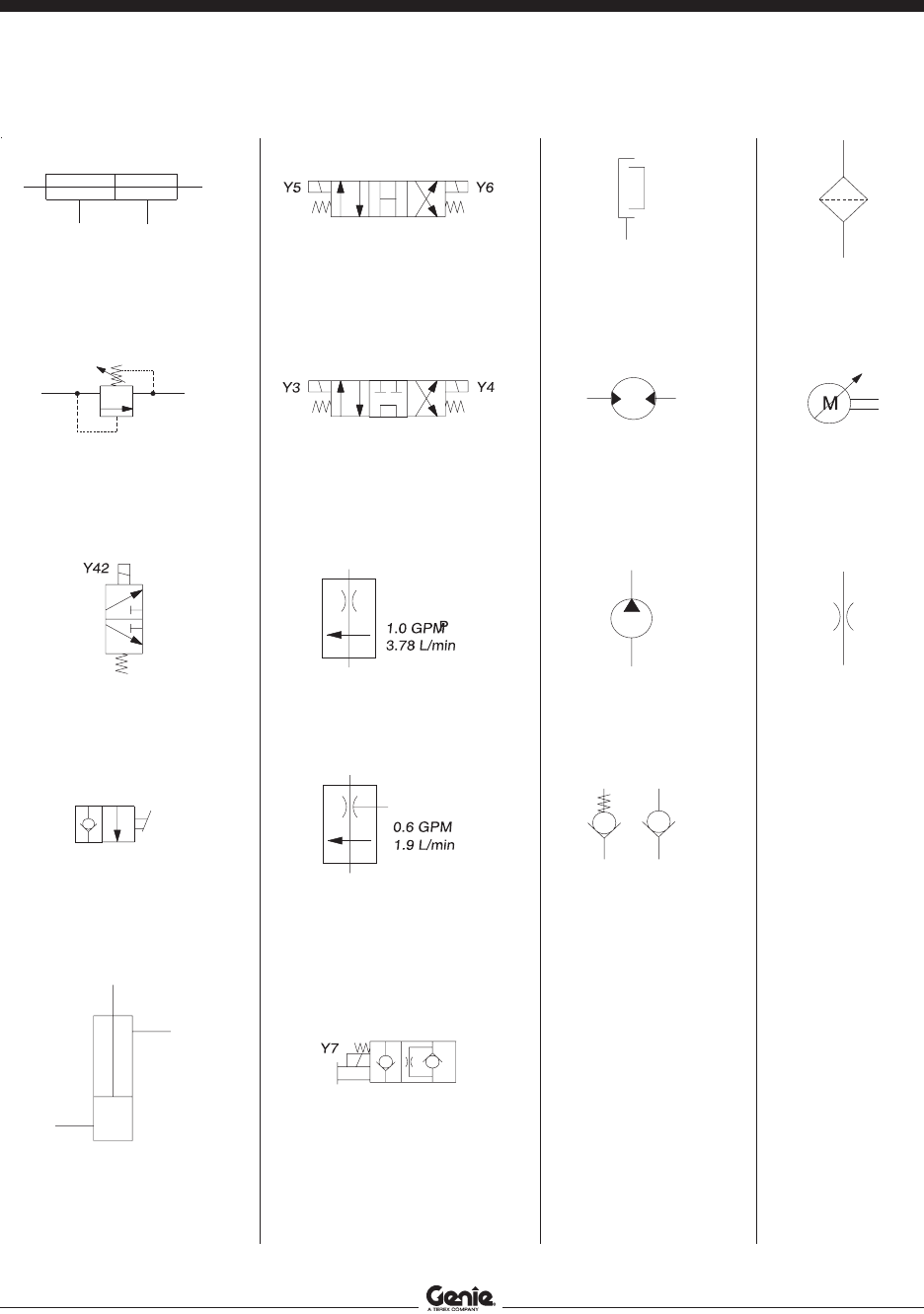
Section 6 • Schematics August 2005
REV B
6 - 22 GS-8 • GR-12 • GR-15 Part No. 72965
Hydraulic Symbols Legend
Double acting cylinder
Relief Valve
Solenoid operated
2 position 2 way
directional valve
Brake release valve
Single acting cylinder
Solenoid operated
3 position 4 way
directional valve
Solenoid operated
3 position 4 way
directional valve
Flow regulator
Priority flow regulator
Solenoid operated
2 position 2 way
directional valve
with manual over ride
Brake
Bi-directional motor
Fixed displacement
pump
Check valve
Filter
Variable speed
motor
Orifice

Section 6 • SchematicsAugust 2005
REV B
Part No. 72965 GS-8 • GR-12 • GR-15 6 - 23
Hydraulic Schematic
(before serial number GR01-249)
ABBREVIATION LEGEND
Item Description
A Test port
B Relief valve, steer circuit
C Drive forward/reverse
D Lift/drive select
E Steer left/right
F Relief valve, lift circuit
G Flow regulator, steer circuit
H Relief valve, system
K Platform down
L Flow regulator, platform up/down circuit
M Check valve, platform up circuit
HS0051C
STEER CYLINDER BRAKES DRIVE MOTORS LIFT CYLINDER
M
Y3 Y4
E
K
Y7
L
1 gpm
3.78 L/min
1000 psi
69 bar
B
D
Y42
G
0.6 gpm
1.9 L/min
H
A
2700 psi
186 bar
2200 psi
151.6 bar
F
EX
T1
T2P
TP
3.5 gpm
13.25 L/min
100 MESH
10 MICRON
LEFT RIGHT
S1 S2 BRK M1 M2
Y5 Y6
C
M
FUNCTION MANIFOLD
HYDRAULIC TANK

Section 6 • Schematics August 2005
REV B
6 - 24 GS-8 • GR-12 • GR-15 Part No. 72965
Hydraulic Schematic
(after serial number GR01-248)
ABBREVIATION LEGEND
Item Description
AA Test port
AB Relief valve, steer circuit
AC Steer left/right
AD Lift/drive select
AE Drive forward/reverse
AF Flow regulator, steer circuit
AG Relief valve, system
AH Relief valve, lift circuit
AI Needle valve, manual brake release
AJ Check valve, brake release circuit
K Platform down
L Flow regulator, platform up/down circuit
M Check valve, platform up circuit
HS0051D
STEER CYLINDER BRAKES DRIVE MOTORS LIFT CYLINDER
M
Y3 Y4
Y5 Y6
AE
K
Y7
L
1 gpm
3.78 L/min
1000 psi
69 bar
AB
AD
Y42
AF
0.6 gpm
1.9 L/min
AG
AA
2700 psi
186 bar
2200 psi
151.6 bar
AH
EX
T1
T2P
TP
3.5 gpm
13.25 L/min
100 MESH
10 MICRON
AC
200 psi
13.7 bar
AJ
AI
Y2
M
LEFT RIGHT
S1 S2 BRK M1 M2
FUNCTION MANIFOLD
HYDRAULIC TANK

Service Manual
GR-8•GR-12•GR-15
Rev B2
Part No.
72965
(from serial number GR-101 to GS05-4999)

Distributed By:
Genie North America
Genie Australia Pty Ltd.
Genie China
Genie Malaysia
Genie Japan
Genie Korea
Genie Brasil
Genie Holland
Phone 425.881.1800
Toll Free USA and Canada
800.536.1800
Fax 425.883.3475
Phone +61 7 3375 1660
Fax +61 7 3375 1002
Phone +86 21 53852570
Fax +86 21 53852569
Phone +65 98 480 775
Fax +65 67 533 544
Phone +81 3 3453 6082
Fax +81 3 3453 6083
Phone +82 25 587 267
Fax +82 25 583 910
Phone +55 11 41 665 755
Fax +55 11 41 665 754
Phone +31 183 581 102
Fax +31 183 581 566
Genie Scandinavia
Genie France
Genie Iberica
Genie Germany
Genie U.K.
Genie Mexico City
Phone +46 31 575100
Fax +
Phone +33 (0)2 37 26 09 99
Fax +33 (0)2 37 26 09 98
Phone +34 93 579 5042
Fax +34 93 579 5059
Phone 0800 180 9017
Fax +49 422 149 1820
Phone +44 (0)1476 584333
Fax +44 (0)1476 584334
Phone +52 55 5666 5242
Fax +52 55 5666 3241
46 31 579020
Phone +49 422 149 1818
