

Preface
Page 1
180/190/200 Horizon
Owners Manual
08/01
This manual will acquaint you with the use and maintenance of your new Four Winns® boat. This manual also
provides special information critical to the safety of the passengers, and longevity of the equipment. The
information on the following page lists the means used to increase the visibility of these important messages.
Also included in your owners packet is the Boating Basics, A Guide to Responsible Boating. This publication
covers the boating basics and should be read along with your Four Winns owners manual before operating your
boat. Review this information in detail.
Four Winns continually strives to improve its products. Unit specifications, including standard and optional
equipment are constantly being modified. Equipment availability is also subject to change. The most
current and accurate information available at the time of publication is included in this manual. Some
variation in equipment, description, location, and details can result.
The information in this manual focuses upon the equipment designed and manufactured by Four Winns on
specific models. When appropriate, please utilize the information pertinent to your specific boat model.
Equipment such as engines, and other accessories are manufactured by others. The information provided in
this manual is intended to be used in conjunction with the information provided by the manufacturers of this
equipment. All information available at the time of manufacture has been included with your owners packet.
Read this entire manual carefully before operating your new boat. Many instructions may require direct
performance of the activity to fully understand the correct method. If you choose to read this manual at home,
remember to take it to the boat with you.
Your Four Winns dealer knows your boat best and is interested in your complete satisfaction. Return to the
dealer for service or other assistance. If you find it necessary to contact Four Winns directly, please refer to the
address information listed below. Be sure to include the boat model, serial number, your daytime telephone
number, and specifics of the information desired.
This manual has been specifically developed for the 180 Horizon® (180H), 190 Horizon® (190H), and 200
Horizon® (200H) models. Please record the model and serial number information below.
Model Serial Number
________________________ __________________________
This manual should be considered part of the boat. Should you sell the boat, pass this manual on to the new
owner. Take special care of this manual. Certain information in this manual may not be available in a replace-
ment manual.
Thank you for joining the Four Winns family. We appreciate your purchase and welcome the opportunity to
demonstrate our commitment to you.
Four Winns Customer Service Department
925 Frisbie Street
Cadillac, Michigan 49601
231-775-1343 (Phone)
231-779-2345 (FAX)
E-Mail Address: [email protected]
© Four Winns, L.L.C. 2001. All Rights Reserved.
PREFACE

Preface
Page 2
180/190/200 Horizon
Owners Manual
08/01
SAFETY WARNINGS
This manual contains instructions critical to the safety of those aboard or the longevity of the equipment. Pay
close attention to all safety warnings. The following safety warnings and instructions are used throughout
the manual and at selected locations on your boat.
This safety symbol and this signal word indicate an imminently hazardous situation which, if not
avoided, WILL result in death or serious injury.
This safety symbol and this signal word indicate a potentially hazardous situation which, if not
avoided, CAN result in severe injury or death.
This safety symbol and this signal word indicate a potentially hazardous situation which, if not
avoided, MAY result in minor or moderate personal injury or property damage. It may also be used
to alert against unsafe practices.
NOTICE
This is used to notify people of installation, operation, or maintenance information which is important
but not hazard-related.
YOU are responsible for your own safety, as well as the safety of your passengers and fellow boaters.
You should fully understand and become familiar with the operating procedures and safety precau-
tions in this manual and any other information in the owners packet before you launch the boat.
Always operate your boat with consideration, courtesy, and common sense.
The warnings in this manual do not and can not address every conceivable situation. Always use common
sense! If you have any questions regarding your boat or its operation, contact your dealer.
The following page illustrates the locations of various warning labels, capacity label and other stickers on
your Four Winns® boat.

Preface
Page 3
180/190/200 Horizon
Owners Manual
08/01
LABEL LOCATIONS
The NMMA capacity label and various warning labels are placed at different locations on each model for your
safety. Additional warnings for fuel leakage, blower operation, and other important information will be im-
printed or located on the dash. Many of these stickers and labels are not required by the U.S. Coast Guard
but are important to ensure the safe operation of your Four Winns® boat. In addition, the Hull Identification
Number plate is permanently attached below the deck-hull joint on the starboard aft corner.
NOTICE
Not all of the warning label stickers are depicted in the following pages. Some of these labels
will be found on appliances i.e. microwave, one burner alcohol stove, dockside power cord.
Be sure to read and follow all manufacturers literature and warning label(s) relating to their
product(s). This literature is included in your owners packet.
Below are letters corresponding to the various locations for each item on the drawings. See pages 4 and 5
for the actual wording of each of the various warning labels found on your boat.
(A) Helm Boarding Ladder Warning (B) Boarding Ladder Warning
(C) Procedure Checklist (D) Equipment Checklist
(E) Capacity Label (F) Powered Ventilation for Gas Engines Label
(G) Ski Tow Warning (H) NMMA Certified
(I) Winning Edge Sticker (J) Armorcote Sticker
CD
IJ
H
F
B
E
A
G

Preface
Page 4
180/190/200 Horizon
Owners Manual
08/01
E. CAPACITY LABEL
NOTE:
WARNING
BEFORE STARTING ENGINE:
EQUIPMENT
DRAIN PLUG - SECURED?
MOVEABLE SEATS - SECURED?
LIFE JACKET - ONE FOR EACH PERSON?
OTHER EMERGENCY GEAR - ON BOARD?
PROCEDURES
EMERGENCY STOP SWITCH - TETHER
HOOKED UP?
EVERYBODY - SEATED IN BOAT? NEVER
ON SEAT BACKS, RAISED SEATS, OR
EDGES OF BOAT!
OPERATORS VISION - UNOBSTRUCTED?
WEATHER CONDITIONS - SAFE TO GO
OUT?
PASSENGERS - AWARE OF EMERGENCY
PROCEDURES?
C & D EQUIPMENT AND
PROCEDURES CHECKLIST
WARNING
DO NOT USE SKI TOW FITTING
FOR LIFTING OR PARASAILING.
FITTING COULD PULL OUT OF
DECK RESULTING IN SERIOUS
INJURY OR DEATH.
G. SKI TOW WARNING LABEL
A. HELM BOARDING LADDER WARNING LABEL
DANGER
SHUT OFF MOTOR WHEN NEAR
SWIMMERS. SEVERE INJURY OR
DEATH WILL RESULT FROM
CONTACT WITH A ROTATING
PROPELLER.
DANGER
NEVER APPROACH OR USE
LADDER WHEN MOTOR IS
RUNNING. SEVERE INJURY
OR DEATH WILL RESULT
FROM CONTACT WITH
ROTATING PROPELLER.
B. BOARDING LADDER WARNING LABEL
WARNINGS LABELS - LOCATIONS SHOWN ON PAGE 3.
WARNING
GASOLINE VAPORS CAN EXPLODE RESULTING
IN INJURY OR DEATH. BEFORE STARTING ENGINE
-CHECK ENGINE BILGE COMPARTMENT FOR
GASOLINE OR VAPORS, AND
-OPERATE BLOWER FOR FOUR MINUTES, AND
VERIFY BLOWER OPERATION.
RUN BLOWER WHEN VESSEL IS OPERATING BE-
LOW CRUISING SPEED.
F. POWERED VENTILATION FOR GAS ENGINES
H. NMMA CERTIFICATION STICKER
CAPACITY WILL VARY DEPENDING
UPON WHICH MODEL YOU HAVE.

Preface
Page 5
180/190/200 Horizon
Owners Manual
08/01
J. ARMORCOAT STICKER
I. WINNING EDGE STICKER
WARNING
NO VENTILATION IS PROVIDED.
FUEL VAPORS ARE A FIRE AND
EXPLOSION HAZARD. TO AVOID
INJURY OR DEATH, DO NOT STORE
FUEL OR FLAMMABLE LIQUIDS HERE.
L. NO VENTILATION WARNING LABEL
WARNING
CARBON MONOXIDE IS PRODUCED BY ALL
GASOLINE ENGINES AND GENERATOR SETS.
AVOID BRAIN DAMAGE OR DEATH FROM CARBON MONOXIDE.
KEEP COCKPIT AND CABIN AREAS WELL VENTILATED.
AVOID BLOCKAGE OF EXHAUST OUTLETS.
SIGNS IF EXPOSURE INCLUDE NAUSEA, DIZZINESS, AND DROWSINESS.
SEE BOAT OWNERS MANUAL FOR MORE DETAILS.
IF USING A CATALYTIC HEATER, PROVIDE VENTILATION.
DO NOT USE CATALYTIC HEATER WHILE SLEEPING.
M. CARBON MONOXIDE WARNING LABEL
WARNING
EXHAUST FUMES FROM ENGINES CONTAIN CARBON MONOXIDE.
BOATS WITH CANVAS DEPLOYED ARE MORE LIKELY TO COLLECT
EXHAUST FUMES. AVOID BRAIN DAMAGE OR DEATH FROM CARBON
MONOXIDE. KEEP COCKPIT AND CABIN AREAS WELL VENTILATED.
SIGNS OF EXPOSURE INCLUDE NAUSEA, DIZZINESS, AND DROWSINESS.
SEE BOAT OWNERS MANUAL FOR MORE DETAILS. IF USING A
CATALYTIC HEATER, PROVIDE VENTILATION. DO NOT USE CATALYTIC
HEATER WHILE SLEEPING.
N. CARBON MONOXIDE CANVAS WARNING LABEL
ADDITIONAL WARNINGS NOT SHOWN ON PAGE 3.
O. TRANSOM/SIDE DOOR WARNING LABEL
WARNING
PREVENT FALLS OVERBOARD.
CLOSE, LATCH, AND STAY
INSIDE GATE WHILE UNDERWAY.
WARNING
AVOID SERIOUS INJURY OR DEATH
FROM FIRE OR EXPLOSION RESULTING
FROM LEAKING FUEL. INSPECT SYSTEM
FOR LEAKS AT LEAST ONCE A YEAR.
K. LEAKING FUEL WARNING LABEL

Preface
Page 6
180/190/200 Horizon
Owners Manual
08/01
A. LOA
B. BEAM
C. KEEL TO W/S SHELF
D. TOTAL HEIGHT
E. TRANSOM ANGLE
F. DEAD RISE
G. OB TRANSOM HEIGHT
H. BRIDGE CLEARANCE
I. COCKPIT STERN HEIGHT
J. COCKPIT HEIGHT HELM
K. FREEBOARD
L. DRAFT
180 HORIZON SPECIFICATIONS
180 HORIZON
SPECIFICATIONS: US METRIC
LOA : 18’ 6" 5.64 m
LOA w/Extended Swim Platform 20’ 2" 6.15 m
Storage Length: 21’ 0" 6.40 m
Beam: 8’ 1" 2.46 m
Keel to Windshield Shelf: 45" 1.14 cm
Total Height: 4’ 10" 1.52 m
Total Height on Trailer 6’ 7" 1.96 m
Transom Angle: 15
o
15
o
Deadrise: 19
o
19
o
OB Transom Height 25" 64 cm
Bridge Clearance: 3’ 9" 1.14 m
Cockpit Height (Stern): 27" 69 cm
Cockpit Height (Helm): 29" 74 cm
Freeboard (Min): 26" 66 cm
Draft (Drive Down): 31" 79 cm
Draft (Drive Up): 14" 36 cm
Fuel: 38 gal 144 l
Passengers: 8 8
Maximum Capacity: 1300 lbs 590 kg
POWER RATINGS & WEIGHTS
Engine Type
Propshaft Power
HP KW
Boat & Engine Weights
LBS KG
4.3 GL/SX 190 142 2690 1220
5.0GL/SX 220 164 2790 1270
5.0GI/SX 250 187 2800 1270
Trailer Weight 780(S) / 880(T) LBS 354(S) / 399(T) KG
®

Preface
Page 7
180/190/200 Horizon
Owners Manual
08/01
A. LOA
B. BEAM
C. KEEL TO W/S SHELF
D. TOTAL HEIGHT
E. TRANSOM ANGLE
F. DEAD RISE
G. OB TRANSOM HEIGHT
H. BRIDGE CLEARANCE
I. COCKPIT STERN HEIGHT
J. COCKPIT HEIGHT HELM
K. FREEBOARD
L. DRAFT
190 HORIZON SPECIFICATIONS
190 HORIZON
SPECIFICATIONS: US METRIC
LOA : 19’ 6" 5.94 m
LOA w/Extended Swim Platform 21’ 2" 6.45 m
Storage Length: 21’ 9" 6.63 m
Beam: 8’ 5" 2.57 m
Keel to Windshield Shelf: 46" 1.17 cm
Total Height: 4’ 11" 1.50 m
Total Height on Trailer 6’ 7" 2.01 m
Transom Angle: 15
o
15
o
Deadrise: 19
o
19
o
Bridge Clearance: 3’ 9" 1.14 m
Cockpit Height (Stern): 28" 71 cm
Cockpit Height (Helm): 29" 74 cm
Freeboard (Min): 26" 66 cm
Draft (Drive Down): 32" 81 cm
Draft (Drive Up): 15" 38 cm
Fuel: 42 gal 159 l
Passengers: 9 9
Maximum Capacity: 1450 lbs 658 kg
POWER RATINGS & WEIGHTS
Engine Type
Propshaft Power
HP KW
Boat & Engine Weights
LBS KG
4.3 GL/SX 190 142 2860 1300
5.0GL/SX 220 164 2960 1340
5.0GI/SX 250 187 2970 1350
Trailer Weight 780(S) / 990(T) LBS 354(S) / 408(T) KG
®

Preface
Page 8
180/190/200 Horizon
Owners Manual
08/01
A. LOA
B. BEAM
C. KEEL TO W/S SHELF
D. TOTAL HEIGHT
E. TRANSOM ANGLE
F. DEAD RISE
G. OB TRANSOM HEIGHT
H. BRIDGE CLEARANCE
I. COCKPIT STERN HEIGHT
J. COCKPIT HEIGHT HELM
K. FREEBOARD
L. DRAFT
200 HORIZON SPECIFICATIONS
200 HORIZON
SP EC IFIC ATION S : U S M E TR IC
LOA : 20’ 6" 6.25 m
LOA w/Extended Swim Platform 22’ 3" 6.78 m
Storage Length: 22’ 2" 6.76 m
Beam: 8’ 6" 2.59 m
Keel to Windshield Shelf: 52" 1.32 cm
Total Height: 5’ 6" 1.68 m
Total Height on Trailer 7’ 0" 2.13 m
Transom Angle: 15
o
15
o
Deadrise: 19
o
19
o
Bridge Clearance: 4’ 3" 1.30 m
Cockpit Height (Stern): 30" 76 cm
Cockpit Height (Helm): 32" 81 cm
Freeboard (Min): 29" 74 cm
Draft (Drive Down): 34" 86 cm
Draft (Drive Up): 17" 43 cm
Fuel: 45 gal 170 l
Passengers: 11 11
Maximum Capacity: 1600 lbs 730 kg
POWER RATINGS & WEIGHTS
Engine Type
Propshaft Power
HP KW
Boat & Engine Weights
LBS KG
5.0GL/SX 220 164 3090 1400
5.0GL/DP 220 164 3110 1410
5.0GI/SX 250 187 3100 1410
5.0GI/DP 250 187 3120 1420
5.7GS/SX 250 187 3090 1400
5.7GS/DP 250 187 3110 1410
5.7SI/SX 280 209 3100 1410
5.7SI/DP 280 209 3120 1420
Trailer Weight 780(S) / 900(T) LBS 354(S) / 408(T) KG
®

Page 1
Table of Contents180/190/200 Horizon
Owners Manual
08/01
OPERATION ............................................................................................................................................. 1
A - 1 GENERAL .................................................................................................................. 1
A - 2 COMPONENT SYSTEMS ........................................................................................... 1
A - 3 SAFETY EQUIPMENT ................................................................................................ 1
A - 4 PASSENGER SAFETY ............................................................................................... 1
A - 5 RULES OF THE ROAD ............................................................................................. 1
A - 6 LIGHTNING ................................................................................................................. 1
A - 7 DRUGS AND ALCOHOL ............................................................................................. 2
A - 8 PRE-CRUISE SYSTEM CHECK .................................................................................. 2
A. Before Starting The Engines .............................................................................. 2
B. After Starting The Engine .................................................................................. 2
A - 9 ENGINE OPERATIONAL PROCEDURES ...................................................................... 2
A. Before Starting .................................................................................................. 2
B. Cold Engine Start (Carbureted Engines) ............................................................ 3
C. Warm Engine Starting ....................................................................................... 3
D. Shifting and Control Speed ............................................................................... 4
E. Stopping Engine ................................................................................................ 4
A - 10 GROUNDING AND TOWING ....................................................................................... 4
A - 11 BOATING EDUCATION ................................................................................................ 5
A. Boating Courses ................................................................................................ 5
B. Boating Manuals and Literature .......................................................................... 5
C. Charts and Maps ................................................................................................ 5
SAFETY EQUIPMENT .............................................................................................................................. 1
B - 1 GENERAL .................................................................................................................... 1
A. Required Safety Equipment .............................................................................. 1
B. Personal Floatation Devices (PFDs) ................................................................... 1
C. PFD Types ......................................................................................................... 1
D. PFD Pointers ..................................................................................................... 2
E. Emergency Stop Switch ..................................................................................... 2
F. Fire Extinguisher ................................................................................................ 3
G. Visual Distress Signal Devices ........................................................................... 3
H. Sound Signaling Devices .................................................................................... 4
I. Navigation Lights ................................................................................................ 4
J. Additional Recommended Equipment ................................................................. 4
B - 2 CARBON MONOXIDE ................................................................................................. 4
A. Properties and Characteristics of Carbon Monoxide ........................................... 5
B. What Makes Carbon Monoxide ......................................................................... 5
C. How a Person is Affected by Carbon Monoxide .................................................. 5
D. Effects of Carbon Monoxide .............................................................................. 5
E. Symptoms ....................................................................................................... 5
F. Treatment (Evacuate, Ventilate, Investigate, Take Corrective Action) ................... 6
G. Inspection ........................................................................................................ 6
H. Operation ......................................................................................................... 6
I. Boathouses, Sea Walls and Other Boats .......................................................... 6
J. Backdrafting (Station Wagon Effect) .................................................................. 7
TABLE OF CONTENTS

Table of Contents
Page 2
180/190/200 Horizon
Owners Manual
08/01
K. Cabin Appliances .............................................................................................. 8
L. Ventilation of Accommodation Spaces ................................................................ 8
M. Running of Engine in Idle .................................................................................... 8
N. Altitude and Sea Conditions .............................................................................. 8
O. Portable Generator Sets ................................................................................... 8
P. Maintenance - Engine Performance ................................................................... 8
Q. Maintenance - External Conditions .................................................................... 8
B - 3 SAFE BOATING PRACTICES ...................................................................................... 9
A. Drugs and Alcohol .............................................................................................. 9
B. Safe Operation ................................................................................................... 9
C. Passenger Safety ............................................................................................... 9
D. Propeller ............................................................................................................ 9
E. First Aid ............................................................................................................10
F. Operation By Minors .........................................................................................10
G. Rules of the Road ...........................................................................................10
H. Voluntary Inspection .........................................................................................10
I. Safe Boating Courses .......................................................................................10
B - 4 WATER SPORTS ........................................................................................................10
A. Water Sport Guidelines .........................................................................................10
B. Water Skiing ......................................................................................................... 11
BASIC SEAMANSHIP ................................................................................................................................ 1
C - 1 GENERAL ................................................................................................................... 1
A. Boating Regulations .......................................................................................... 1
B. Rules of Seamanship ........................................................................................ 1
C - 2 NAVIGATIONAL AIDS .................................................................................................. 3
A. International Association of Lighthouse Authorities System B (IALA-B) ............. 3
B. Lateral Markers .................................................................................................. 3
C. Safe Water Markers ........................................................................................... 3
D. The Uniform State Waterway Marking System ................................................... 4
E. A Special Sign .................................................................................................... 4
F. Noise ................................................................................................................. 4
C - 3 RECOMMENDED READING ....................................................................................... 4
C - 4 CONTACTS .................................................................................................................. 4
C - 5 OWNERS LOGS AND RECORDS .............................................................................. 5
C - 6 NAVIGATIONAL AIDS CHART ...................................................................................... 5
WARRANTY AND SERVICE ...................................................................................................................... 1
D - 1 FOUR WINNS WARRANTY POLICY .......................................................................... 1
D - 2 HULL STRUCTURE WARRANTY ................................................................................ 1
D - 3 WARRANTY REGISTRATION ..................................................................................... 1
D - 4 TRANSFER OF WARRANTY ...................................................................................... 1
D - 5 PRE-OWNED UNIT REGISTRATION ........................................................................... 1
D - 6 INSURANCE COVERAGE .......................................................................................... 2
D - 7 SERIAL NUMBER RECORD ....................................................................................... 2
D - 8 PRE-DELIVERY SERVICE ......................................................................................... 2
D - 9 REPLACEMENT PARTS ............................................................................................. 2
D - 10 WINNGEAR ............................................................................................................ 2

Page 3
Table of Contents180/190/200 Horizon
Owners Manual
08/01
ENGINES AND INSTRUMENTATION ......................................................................................................... 1
E - 1 GENERAL .............................................................................................................................. 1
E - 2 ENGINE EXHAUST ................................................................................................................ 1
E - 3 ENGINES ............................................................................................................................... 2
E - 4 PROPELLERS ....................................................................................................................... 2
A. Diameter .......................................................................................................................... 2
B. Pitch ................................................................................................................................ 2
C. Prop Slip ......................................................................................................................... 2
E - 5 RUNNING ANGLE & POWER TRIM/TILT ................................................................................. 3
A. Power Trim ...................................................................................................................... 3
B. Power Tilt ........................................................................................................................ 3
E - 6 ENGINE INSTRUMENTATION ................................................................................................. 3
A. Tachometer ...................................................................................................................... 4
B. Speedometer ................................................................................................................... 4
C. Temperature Gauge .......................................................................................................... 4
D. Oil Pressure Gauge ......................................................................................................... 5
E. Voltmeter ......................................................................................................................... 5
F. Fuel Gauge ...................................................................................................................... 5
G. Power Trim Gauge ........................................................................................................... 5
H. Four Winns/VDO Module Display Settings ........................................................................ 5
I. Ignition Switch ................................................................................................................. 7
J.. Emergency Stop Switch ................................................................................................... 7
K. Engine Hour Meter ........................................................................................................... 8
L. Alarm Systems ................................................................................................................ 8
M. Instrument Maintenance ................................................................................................... 8
N. VDO Module Quick Start Card ........................................................................................... 9
CONTROL SYSTEMS ............................................................................................................................... 1
F - 1 GENERAL .............................................................................................................................. 1
F - 2 CONTROL OPERATION ......................................................................................................... 1
A. Carbureted Engines .......................................................................................................... 1
B. Fuel Injected Engines (EFI) ............................................................................................... 2
F - 3 NEUTRAL SAFETY SWITCH .................................................................................................. 2
F - 4 CONTROL SYSTEM MAINTENANCE ..................................................................................... 2
STEERING SYSTEMS ............................................................................................................................... 1
G - 1 GENERAL .............................................................................................................................. 1
A. Rotary Steering ................................................................................................................ 1
B. Tilt Steering ...................................................................................................................... 1
C. Power Steering ................................................................................................................. 1
G - 2 PROPELLER TORQUE .......................................................................................................... 2
G - 3 STEERING SYSTEM MAINTENANCE .................................................................................... 2
A. General Maintenance ....................................................................................................... 2
B. Rotary System Maintenance ............................................................................................ 2
C. Winter Storage ................................................................................................................. 3

Table of Contents
Page 4
180/190/200 Horizon
Owners Manual
08/01
ELECTRICAL SYSTEMS ........................................................................................................................... 1
H - 1 GENERAL .............................................................................................................................. 1
H - 2 BATTERY SYSTEM ............................................................................................................... 1
A. Single Battery System ..................................................................................................... 1
H - 3 12 VOLT ELECTRICAL EQUIPMENT ...................................................................................... 1
A. Helm Equipment .............................................................................................................. 1
B. Installation of Additional 12 Volt Equipment ....................................................................... 2
C. Interior Equipment ............................................................................................................ 2
H - 4 ELECTRICAL SYSTEM MAINTENANCE ................................................................................. 3
A. Battery Maintenance ........................................................................................................ 3
B. Electrical Wiring Maintenance .......................................................................................... 3
H - 5 STRAY CURRENT CORROSION ............................................................................................ 4
A. General ............................................................................................................................ 4
B. Galvanic Corrosion ........................................................................................................... 5
C. Corrosion Prevention ........................................................................................................ 5
FUEL SYSTEMS ....................................................................................................................................... 1
I - 1 GASOLINE FUEL SYSTEMS ................................................................................................. 1
A. System Testing ................................................................................................................ 1
B. Fuel Fills ......................................................................................................................... 1
C. Anti-Syphon Valves .......................................................................................................... 2
D. Fuel Gauge ...................................................................................................................... 2
E. Fuel Senders ................................................................................................................... 2
F. Fuel Filters ...................................................................................................................... 3
G. Use and Maintenance ...................................................................................................... 3
I - 2 FUEL STANDARDS ................................................................................................................ 3
A. Problems With Alcohol in Gasoline ................................................................................... 3
B. Recommendations ........................................................................................................... 4
I - 3 FUELING INSTRUCTIONS ...................................................................................................... 4
VENTILATION AND DRAINAGE SYSTEMS .............................................................................................. 1
J - 1 ENGINE COMPARTMENT VENTILATION ............................................................................... 1
A. Gravity Ventilation System ............................................................................................... 1
B. Forced Air Ventilation ....................................................................................................... 1
C. Engine Ventilation System Maintenance ........................................................................... 1
J -2 HULL DRAINAGE SYSTEMS ................................................................................................. 1
A. Transom Drain ................................................................................................................. 1
B. Bilge Pumps .................................................................................................................... 1
C. Liner Drains ..................................................................................................................... 2
D. Bilge Compartment Drainage ............................................................................................ 2
INTERIOR EQUIPMENT ............................................................................................................................ 1
K - 1 GLOVE BOX .......................................................................................................................... 1
K - 2 BUILT-IN COOLER ................................................................................................................. 1
K - 3 STEREO ................................................................................................................................ 1
K - 4 CHERRY HELM ENHANCEMENTS ....................................................................................... 1
K - 5 ANCHOR LOCKER STORAGE .............................................................................................. 2
K - 6 SKI STORAGE LOCKER ....................................................................................................... 2
K - 7 WALK-THRU DOORS ............................................................................................................ 2

Page 5
Table of Contents180/190/200 Horizon
Owners Manual
08/01
K - 8 BOW FILL-IN CUSHIONS ...................................................................................................... 2
K - 9 WALK-THRU STORAGE LOCKERS ...................................................................................... 3
EXTERIOR EQUIPMENT ........................................................................................................................... 1
L - 1 RAILS & DECK HARDWARE ................................................................................................. 1
A. Rails ................................................................................................................................ 1
B. Cleats .............................................................................................................................. 1
C. Stern Rail with Tow Ring .................................................................................................. 1
D. Maintenance ...................................................................................................................... 1
L - 2 WINDSHIELDS ...................................................................................................................... 1
L - 3 SWIM PLATFORM - STERN LADDER ................................................................................... 2
L - 4 ADD-ON SWIM PLATFORM OPTION .................................................................................... 2
L - 5 ANCHOR & ANCHORING ...................................................................................................... 3
L - 6 DEPTHSOUNDER ................................................................................................................... 4
L - 7 WAKE BOARD TOWER OPTION ............................................................................................ 4
UPHOLSTERY .......................................................................................................................................... 1
M - 1 EXTERIOR SEATING ............................................................................................................. 1
A. Cockpit Tables ................................................................................................................. 1
B. Bow Seating .................................................................................................................... 1
C. Jump Seats ..................................................................................................................... 1
D. Lounger ........................................................................................................................... 2
E. Top Storage ....................................................................................................................... 2
F. Bucket Seats (Sunsport Seating Option) ......................................................................... 3
G. Sundeck (Sunsport Seating Option)................................................................................... 4
I. Sunsport Couch ................................................................................................................. 4
M - 2 EXTERIOR UPHOLSTERY CARE ........................................................................................... 4
M - 3 REPLACEMENT UPHOLSTERY ............................................................................................ 5
M - 4 CARPET CARE ..................................................................................................................... 5
A. Interior and Exterior Carpet ............................................................................................... 5
B. Cleaning and Maintenance ............................................................................................... 5
C. Stain Removal Testing ...................................................................................................... 6
D. Stain Removal Procedures ............................................................................................... 6
WEATHER COVERS ................................................................................................................................. 1
N - 1 GENERAL INFORMATION ..................................................................................................... 1
A. Convertible Top (Suntop) .................................................................................................. 1
B. Side Curtains ................................................................................................................... 2
C. Aft Curtains ..................................................................................................................... 2
D. Forward Cover .................................................................................................................. 2
E. Bimini Top (Southwest) ...................................................................................................... 2
F. Cockpit Cover .................................................................................................................... 3
G. Mooring Cover ................................................................................................................... 3
N - 2 TRAILERING .......................................................................................................................... 4
N - 3 WINTER STORAGE ............................................................................................................... 4
N - 4 MAINTENANCE ..................................................................................................................... 4
N - 5 USE OF WEATHER COVERS AND CARBON MONOXIDE .................................................... 5

Table of Contents
Page 6
180/190/200 Horizon
Owners Manual
08/01
FIBERGLASS AND HULL INFORMATION ................................................................................................ 1
O - 1 HULL DESIGN INFORMATION ................................................................................................ 1
O - 2 FIBERGLASS CONSTRUCTION ............................................................................................. 1
O - 3 EQUIPMENT INSTALLATION .................................................................................................. 1
O - 4 FIBERGLASS CARE & MAINTENANCE ................................................................................. 2
A. General Maintenance ....................................................................................................... 2
B. Weathering Effects on Gel Coat ....................................................................................... 2
C. Stains .............................................................................................................................. 3
O - 5 FIBERGLASS REPAIRS ........................................................................................................ 3
A. Scratches ........................................................................................................................ 4
B. Gouges & Cracks ............................................................................................................ 4
C. Osmotic Blistering ........................................................................................................... 5
O - 6 ANTIFOULING PAINT ............................................................................................................. 5
O - 7 HULL SUPPORT .................................................................................................................... 5
WOODWORK AND COMPOSITES ........................................................................................................... 1
P - 1 HIGH-PRESSURE LAMINATE CARE ..................................................................................... 1
P - 2 STAR BOARD ........................................................................................................................ 1
P - 3 CHERRY ENHANCEMENTS ................................................................................................. 1
GENERAL MAINTENANCE ....................................................................................................................... 1
Q - 1 WINTERIZATION .................................................................................................................... 1
A. Prior to Lifting for Winter Lay-up ....................................................................................... 1
B. After Lifting ....................................................................................................................... 1
C. Prior to Winter Storage ..................................................................................................... 1
Q - 2 ENGINE FLUSH OUT ............................................................................................................. 2
Q - 3 GENERAL MAINTENANCE SCHEDULE ................................................................................. 3
TRAILERS ................................................................................................................................................ 1
R - 1 GENERAL TRAILER INFORMATION ...................................................................................... 1
A. Regulations ...................................................................................................................... 1
B. Load Carrying Capacity ..................................................................................................... 1
C. Hitches ............................................................................................................................. 2
R - 2 TRAILER COMPONENTS ....................................................................................................... 2
A. Bunk Supports .................................................................................................................. 2
B. Tongue .............................................................................................................................. 2
C. Swivel Jack ....................................................................................................................... 3
D. Coupling Assembly ........................................................................................................... 4
E. Surge Disc Brakes ............................................................................................................ 4
F. Winch ............................................................................................................................... 5
G. Wheels ............................................................................................................................. 6
H. Spare Tire Carrier ............................................................................................................. 6
I. Lights .............................................................................................................................. 7
J. Tie-downs ......................................................................................................................... 7
R - 3 OPERATION .......................................................................................................................... 8
A. Hitching Trailers ............................................................................................................... 8
B. Backing Up With Surge Disc Brakes ................................................................................ 9

Page 7
Table of Contents180/190/200 Horizon
Owners Manual
08/01
R - 4 TRAILERING ........................................................................................................................ 10
A. Checklist ....................................................................................................................... 10
B. Tactics ........................................................................................................................... 10
R - 5 MAINTENANCE .................................................................................................................... 11
A. Care of Exterior Finish .................................................................................................... 11
B. Bunks ............................................................................................................................. 11
C. Swivel Jack ..................................................................................................................... 11
D. Brake Actuator & Coupling Assembly .............................................................................. 11
E. Winch ............................................................................................................................. 11
F. Lights ............................................................................................................................. 11
G. Tie-downs ....................................................................................................................... 12
H. Wheels ........................................................................................................................... 12
I. Brakes ............................................................................................................................ 12
J. Bearings ......................................................................................................................... 12
R - 6 AXLE INSPECTION & REPAIRS ............................................................................................ 12
A. Removal of Hub .............................................................................................................. 13
B. Bearing/Seal Inspection and Replacement ...................................................................... 13
C. Hub Reinstallation .......................................................................................................... 13
GLOSSARY ......................................................................................................................................... 1
FLOAT PLAN ........................................................................................................................................... 1
FUEL LOG ................................................................................................................................................ 1
SERVICE LOG .......................................................................................................................................... 1
SERVICE INFORMATION ......................................................................................................................... 1
ELECTRICAL SCHEMATICS ..................................................................................................................... 1

Section A
Page 1
180/190/200 Horizon
Owner’s Manual
08/01
A - 1 GENERAL
Before starting the boat, become familiar with all of the
various systems and related operations. Be sure all
necessary safety equipment is on-board. Know the “Rules
of the Road”. Have an experienced operator brief you on
the general operation of your new boat. Perform a “Pre--
Cruise Systems Check”. This manual is a part of your
boat’s equipment. Always keep it on board.
A - 2 COMPONENT SYSTEMS
Before you can really enjoy your boat, a thorough under-
standing of its systems and their operation is essential.
This manual and the associated manufacturers informa-
tion are included in the owner’s packet. This informa-
tion is provided to enhance your knowledge of the boat.
Read this information carefully.
After becoming familiar with the boat and its systems,
reread this manual. Maintenance and service tips are
included to help keep the boat in like-new condition.
A - 3 SAFETY EQUIPMENT
Besides the equipment installed on the boat by
Four Winns, L.L.C., certain other equipment is required
for passenger safety. A brochure listing the Federal equip-
ment requirements is included in the owner’s packet or
is available through your local U.S. Coast Guard Sta-
tion. Remember that these laws are for your protection
and are minimum requirements. Check your local and
state regulations, also.
Items like a sea anchor, working anchor, extra dock lines,
flare pistol, a line permanently secured to your ring buoy,
etc. could at some time save your passengers lives, or
save your boat from damage.
The Coast Guard Auxiliary offers a “Courtesy Examina-
tion.” This inspection will confirm the boat is equipped
with all of the necessary safety equipment.
A - 4 PASSENGER SAFETY
You are responsible for the safety of your passengers as
well as for their behavior while aboard. Make sure:
1. Each passenger is properly instructed in Personal
Flotation Device (PFD) use and keeps one within
reach in case of emergency. All nonswimmers and
children should wear a PFD at all times when under-
way.
2. Passengers do not sit on gunwales, open decks, el-
evated pedestal seats or on seat backs when the
boat is underway. This could cause them to be thrown
overboard during a sudden maneuver.
3. At least one other person knows how to operate the
boat in case of an emergency.
A - 5 “RULES OF THE ROAD”
As in driving an automobile, there are a few rules that
must be known if safe boating operation is to be main-
tained. The Coast Guard, Coast Guard Auxiliary, Depart-
ment of Natural Resources or your local boat club spon-
sor courses in boat handling, including “rules of the road”.
Such courses are strongly recommended. Books on this
subject are also available from local libraries.
A - 6 LIGHTNING
When boating, it is important to be aware of the weather
around you. When the weather changes for the worse,
DO NOT jeopardize your safety by trying to “ride out the
storm”. If possible, return to safe harbor and dock your
vessel immediately.
If caught in a storm, seek shelter inside the cabin and
wait for the storm to pass. With open bow models, suntops
and campers will provide some protection, but should not
be relied on if you are able to return to shore. Exercise
care when high winds are present!
OPERATION
Section A
Page 2
180/190/200 Horizon
Owner’s Manual
08/01
DO NOT swim or dangle legs or arms into the
water during a lightning storm. Stay out of the
water!
Lightning will seek a ground when it strikes. Avoid con-
tact with metal parts such as bow rails, control handle, or
windshield.
A - 7 DRUGS AND ALCOHOL
Please keep in mind that along with the fun of boating
comes responsibility. As the owner or operator of a plea-
sure boat, you are obligated (morally and legally) to use
good judgement while underway in providing for the safety
and well-being of your passengers and other boaters
around you.
A common and flagrant violation of good judgement and
the law by mariners involves the use of alcohol or drugs.
Each year, about half of all accidents involving fatalities
involve the use of alcohol or drugs.
It is a federal offense to operate a boat while intoxicated.
Criminal penalties may include the termination of operat-
ing privileges for up to one year. Many states have passed
similar laws.
Alcohol or drugs have an inhibiting effect on the judge-
ment and reaction time of the boat operator and his/her
passengers. Heed the advice of experts and statisti-
cians...DO NOT drink or use drugs when operating a boat.
NEVER allow an obviously intoxicated person to take the
helm.
Have fun in your Four Winns® boat, but also have the
good sense to be mentally alert and physically capable
of operating the boat in a safe manner.
A - 8 PRE-CRUISE SYSTEM CHECK
Before leaving the dock, the following items should be
checked:
A. Before Starting The Engine
1. Check the weather forecast. Determine if the cruise
planned can be made safely.
2. Be sure all necessary safety equipment is on board
and operative. This includes items such as the run-
ning lights, horn, spotlight, life saving devices, etc.
3. Check the bilge water level and bilge pump opera-
tion. Check the engine and drive fluid levels. Look
for other signs of potential problems. Check for the
scent of fuel fumes.
4. Activate the Bilge Blower. Check the blower output.
Gasoline vapors can explode resulting in injury
or death. Before starting the engine, check
engine compartment bilge for gasoline or vapors.
Operate blower for four minutes, and verify blower
operation. ALWAYS run the blower when the
vessel is operating below cruising speed.
5. Ensure an adequate amount of fuel is on board.
6. Be sure you have sufficient water and other provi-
sions on board for the cruise planned.
7. Leave a written message listing details of the planned
cruise with a close friend ashore.
B. After Starting The Engine
1. Visibly check the engine to be sure there are no ap-
parent water or oil leaks.
2. Check the gauges. Make sure the oil pressure, wa-
ter temperature, voltmeter, etc. are reading normally.
3. Have a safe cruise and enjoy yourself.
Always be sure to raise and secure the anchor
prior to operating your boat. Failure to raise
and secure anchor before getting underway
could result in damage to boat and even severe
injury or death from a rebounding anchor.
A - 9 ENGINE OPERATIONAL PROCEDURES
A. Before Starting
1. Check the engine compartment for water, gas, and/
or oil leaks of any kind. Keep the bilge in a clean
condition to prevent blower and bilge pump damage,
and fire hazards.

Section A
Page 3
180/190/200 Horizon
Owner’s Manual
08/01
2. Check the fluid levels of the engine oil and power
steering system daily. Fill oil or steering fluid as re-
quired by the indications on the dip sticks. Refer to
the Table 1: “SAE Viscosity Chart” and your engine
manual included in the owner’s packet. DO NOT
USE MULTIGRADE OIL. Power steering and power
trim use automatic transmission fluid. Check the
fluid levels in the vertical drive units or transmission
as often as practical.
Table 1: SAE Viscosity Chart
3. Start and operate the bilge blower system for at least
four (4) minutes before start-up.
4. Lower the vertical outdrive units (on applicable mod-
els) making sure the water intakes are under the water.
B. Cold Engine Start (Carbureted Engines)
1. The engine may require priming prior to starting. To
prime the engine, proceed as follows:
a. Place ignition switch in the OFF position.
b. Disengage shift mechanism.
c. Move control handle to the full throttle position;
this operates accelerator pump and primes the
engine.
d. Repeat priming, if necessary.
e. Return the control handle to fast idle position.
2. Turn key switch to START position and hold until
engine starts. DO NOT hold in START position for
more than ten seconds. In colder weather, more prim-
ing may be necessary. However, too much priming
may flood engine.
IF THE LOWEST
ANTICIPATED
TEMPERATURE IS*
THE FOLLOWING
SAE VISCOSITY OILS
ARE RECOMMENDED
32
O
F (0
o
C) and above
SAE 30
0
O
F (-18
O
C) to 32
O
F (0
O
C)
SAE 20W-20
Below 0
O
F (-18
O
C)
SAE 10W
*Temperature range you expect to operate.
Note: Use only single viscosity oils.
If engine floods:
• Disengage shift. Move handle to full throttle position.
• Turn key switch to the START position.
• Immediately move the control handle to the idle posi-
tion when the engine starts.
NOTICE
Failure to move the control handle to the idle
position immediately when engine starts will al-
low engine to “over-rev” and engine damage could
result. “Over-revving” engine after off-season stor-
age could also damage the water pump impeller.
When starting engine for the first time after
off-season storage, always idle engine for
one minute to allow the water pump to
prime.
3. As soon as engine starts:
a. Release key to the ON or RUN position.
b. Move control handle to the fast idle position to
warm up engine. DO NOT exceed 1000 RPM.
NOTICE
Cold engine starting procedures are different for
EFI engines. Priming is not necessary. Refer to
the engine owner’s manual for additional informa-
tion.
C. Warm Engine Starting
1. Move control handle to the neutral detent position.
2. Turn key switch to START position and hold until
engine starts, but DO NOT hold in start position for
more than ten seconds. If engine does not start, let
go momentarily, then try again.
3. As soon as engine starts, release key to the ON or
RUN position.
NOTICE
NEVER turn key to START position when en-
gine is running.
NOTICE
Warm engine starting procedures are different
for EFI engines. Refer to the engine owner’s
manual for additional information.

Section A
Page 4
180/190/200 Horizon
Owner’s Manual
08/01
D. Shifting and Control Speed
NOTICE
If your boat is equipped with a non-OEM remote
control system, ask your dealer how to properly
operate it.
1. Move control handle to the neutral detent (idle) posi-
tion. This will engage neutral start switch and allow
engine to start.
DO NOT shift into FORWARD or REVERSE un-
less engine is running. Damage to the shift sys-
tem could result from trying to shift without the
engine running. Carefully check function of all
control and engine systems before leaving the
dock.
2. To go FORWARD - actuate the neutral lock mecha-
nism and briskly move the shift handle forward. Throttle
movement will begin after forward gear engagement.
3. To go in REVERSE - actuate the neutral lock mecha-
nism and briskly move the shift handle rearward.
Throttle movement will begin after reverse gear en-
gagement.
DO NOT shift from forward to reverse when the
boat is planing.
NOTICE
DO NOT shift if engine speed is above 800 RPM.
4. To go from FORWARD to REVERSE, or REVERSE
to FORWARD; always pause at NEUTRAL and allow
engine speed to return to idle.
5. After shifting is completed, continue to move the con-
trol handle slowly in the desired direction to increase
speed.
Any time the boat is operated, be aware of
changes in shift system operation. A sudden
increase in shift effort at the remote control
handle, or other abnormal operation, indicates
a possible problem in the shift system. If this
occurs, the following precautions must be taken:
• With engine running and boat securely tied
to the dock, shift drive into forward and re-
verse to ensure there is gear engagement.
• When docking the boat, all docking maneu-
vers must be performed at slow speed. Pay
special attention to other boaters. Passen-
gers should be informed of potential prob-
lems and precautions taken.
If you suspect there is a problem, see your engine
manufacturer’s certified service dealer or Four Winns
dealer as soon as possible for proper diagnosis and re-
quired service or adjustment. Continued operation could
result in damage to the shift mechanism and loss of con-
trol.
E. Stopping Engine
1. Move control handle to the NEUTRAL position.
2. Turn ignition key to the OFF position.
NOTICE
DO NOT stop engine at speeds above idle or
“speed up” engine while turning off ignition.
Engine damage could result.
A - 10 GROUNDING AND TOWING
If the boat should become disabled, or if assist-
ing another craft that is disabled, great care must
be taken. The stress applied to a boat during
towing may become excessive. Excessive
stress can damage the structure of the boat and
create a safety hazard for those aboard.

Section A
Page 5
180/190/200 Horizon
Owner’s Manual
08/01
Four Winns® boats are not designed nor intended to be
used as a towing vessel. The mooring cleats on
Four Winns® boats are not designed or intended to be
used for towing purposes. These cleats are specifically
designed as mooring cleats for securing the boat to a
dock, pier, etc. DO NOT use these fittings for towing or
attempting to free a grounded vessel.
Freeing a grounded vessel or towing a boat that is dis-
abled requires specialized equipment and knowledge.
Line failure and structural damage caused by improper
towing have resulted in fatal injuries. Because of this,
Four Winns strongly suggests that these activities be
left to those who have the equipment and knowledge,
such as the U.S. Coast Guard or Sea Tow, to safely
accomplish the towing task.
Running aground can cause serious damage to
a boat and associated underwater gear. If the
boat should become grounded, distribute per-
sonal flotation devices and inspect the boat for
possible damage. Thoroughly inspect the bilge
area for signs of leakage. An experienced ser-
vice facility should check the hull and underwater
gear at the first opportunity. DO NOT continue
to use the boat if the condition of the hull or un-
derwater equipment is questionable.
If towing or being towed is absolutely necessary, use the
strongest lines available, and attach them to the bow
eyes or stern eyes only. Have all passengers slip on life
jackets and take a seat in the cabin or other protected
area.
Lines can snap or other hardware can be loos-
ened or broken while towing. Under certain con-
ditions, this can cause severe injury or fatality.
A - 11 BOATING EDUCATION
A. Boating Courses
Boating education classes are offered throughout the
country. The United States Coast Guard Auxiliary offers
free courses on different topics usually during the off-
season. The most popular course is the “Boating Skills
& Seamanship Course,” and information can be obtained
by calling 1-800-336-BOAT.
The United States Power Squadron also offers free courses
ranging from basic seamanship to celestial navigation.
For information, contact your local Power Squadron, or
write: U.S.P.S., P.O. Box 30423, Raleigh, NC 27622.
The Red Cross offers power boating and canoeing classes.
Contact: Director of Water Safety, American National Red
Cross, 17th & D Streets N.W., Washington, DC 20006.
The Canadian Power and Sail Squadron offers seaman-
ship courses. Information can be obtained by calling
1-800-268-3579 (Canada only).
B. Boating Manuals and Literature
A good source of information is the U.S. Coast Guard’s
home study book called “The Skipper’s Course”. This
book may be purchased through: Superintendent of Docu-
ments, U.S. Government Printing Office, Washington, DC
20402, Stock # 050-012-00159-6.
Another good source of boating information is Chapman’s
“Piloting, Seamanship and Small Boat Handling”. Also,
check the local library or bookstore for additional informa-
tion on boating.
C. Charts and Maps
U.S. nautical charts are sold throughout the country at
Governmental Printing Office stores and other agents. A
chart catalog is available by writing to: National Oceanic
and Atmospheric Administration, National Ocean Survey,
Rockville, MD 20852.
In addition, many federal agencies publish recreational
maps, including the U.S. Army Corp. of Engineers, the
Forest Service, the National Park Service, and the Ten-
nessee Valley Authority.
Addresses of all state boating agencies are listed in “A
Boater’s Guide”. For a free copy, write to: National Ma-
rine Manufacturers Association, 401 N. Michigan Avenue,
Chicago, IL 60611.

Section B
Page 1
180/190/200 Horizon
Owner’s Manual
08/01
B - 1 GENERAL
As the owner/operator of the boat, you are responsible
for assuring that all required safety equipment is aboard.
You should also consider supplying additional equipment
as needed for your safety and that of your passengers.
Check state and local regulations and call the U.S. Coast
Guard Boating Safety Hotline at 1-800-368-5647 for in-
formation about required safety for information about
required safety equipment.
A. Required Safety Equipment
Most of the safety equipment required by federal regu-
lations is provided as standard equipment. Personal
Floatation Devices (life jackets) must fit the person wear-
ing it. If local regulations require additional equipment,
it must be approved by the U.S. Coast Guard (USCG).
Minimum requirements include the following:
• Personal Floatation Devices
• Visual Distress Signal
• Bell or Whistle
• Fire Extinguisher
• Navigation Lights
NOTICE
As the owner/operator of the boat, you are re-
sponsible for assuring that all required safety
equipment is aboard and meets the boating
regulations as prescribed by both federal and
local authorities in your area.
B. Personal Floatation Devices (PFDs)
Federal regulations require that you have at least one
Coast Guard approved personal floatation device (PFD)
for each person in a recreational boat. You should not
use your boat unless all PDFs are in serviceable condi-
tion, readily accessible, legibly marked with the Coast
Guard approval number, of an appropriate size (within
the weight range and chest size marked on the PDF)
for each person aboard.
A PFD provides buoyancy to help keep your head above
the water and to help you remain in a satisfactory posi-
tion while in the water. Body weight and age should be
considered when selecting a PFD. The buoyancy pro-
vided by the PFD should support your weight in water.
The size of the PFD should be appropriate for the
wearer. Body weight or chest size are common meth-
ods used to size PFDs. It is your responsibility to en-
sure that you have the proper number and types of
PFDs on board and that your passengers know where
and how to use them.
C. PFD Types
Five types of PFDs have been approved by the U.S.
Coast Guard. The PFDs are described as follows:
PFD Type 1, Wearable (Figure B1) has the greatest
required buoyancy. Its design allows for turning most
unconscious persons in the water from face down po-
sition to a vertical or slightly backward, face-up posi-
tion. It can greatly increase the chances of survival.
Type 1 is most effective for all waters, especially off-
shore when rescue may be delayed. It is also the most
effective in rough waters.
Figure B1: Type I, Wearable
PFD Type II, Wearable (Figure B2) turns its wearer in
the same way as Type I, but not as effectively. The
Type II does not turn as many persons under the same
conditions as a Type I. You may prefer to use this PFD
where there is a probability of quick rescue such as in
areas where other people are commonly involved in
water activities.
Figure B2: Type II, Wearable
SAFETY EQUIPMENT

Section B
Page 2
180/190/200 Horizon
Owner’s Manual
08/01
D. PFD Pointers
The purpose of a PFD is to help save your life. If you
want it to support you when you are in the water, it needs
to fit, float, and be in good condition.
1. Try the PFD on and adjust it until it fits comfortably
in and out of the water. Mark your PFD if you are
the only wearer.
2. To make sure the PFD works, wear it in the water.
This will show you how it works and give you confi-
dence when you use it.
3. Teach children how to put a PFD on and allow them
to try it in the water. That way, they know what the
PFD is for and how it works. They will feel more
comfortable with it if they suddenly find themselves
in the water.
4. If the PFD is wet, allow it to dry thoroughly before
storing it. Do not dry it in front of a radiator or heater.
Store it in a well ventilated area.
5. Keep PFDs away from sharp objects which can
tear the fabric or puncture the floatation pads.
6. For their own safety and the safety of others, all
nonswimmers, poor swimmers, and small children
should wear PFD’s at all times, whether the boat is
stationary or moving.
7. Check the PFD frequently to make sure that it is
not torn, that floatation pads have no leaks, and
that all seams and joints are securely sewn.
8. If a PFD contains kapok, the kapok fibers may be-
come waterlogged and lose their buoyancy after
the vinyl inserts are punctured. If the kapok be-
comes hard or if it is soaked with water replace it,
otherwise, it may not work when you need it.
E. Emergency Stop Switch
This safety device automatically stops the engine if the
lanyard is attached to the operator and the operator
falls from his work station. Refer to the engine manual
for detailed information about using this switch.
The emergency stop switch (Figure B6) incorporates a
shutoff switch, switch clip, lanyard, and lanyard clip. The
lanyard clip must be securely attached to the operator’s
PFD, clothing, arm, or leg. Be sure to attach the lan-
PFD Type III, Wearable (Figure B3) allows the wearer
to place themselves in a vertical or slightly backward
position. It does not turn the wearer. It maintains the
wearer in a vertical or slightly backward position and
has no tendency to turn the wearer face down. It has
the same buoyancy as a Type II PFD and may be ap-
propriate in areas where other people are commonly
involved in water activities.
Figure B3: Type III, Wearable
PFD Type IV, Throwable (Figure B4) is required in ad-
dition to the PFDs previously discussed. The most com-
mon Type IV PFD is a buoyant cushion or ring buoy. It
is designed to be thrown to a person in the water,
grasped and held by the user until he or she is res-
cued. A Type IV PFD should always be in serviceable
condition and immediately available for use. Grasping
this PFD may be difficult if the rescue is delayed or if
the user is overcome by hypothermia (loss of body heat).
Figure B4: Type IV, Throwable
PFD Type V, Wearable (Figure B5) when inflated, it
provides buoyancy equivalent to Type I, II, or III PFDs.
When it is deflated, however, it may not support some
people.
Figure B5: Type V, Wearable

Section B
Page 3
180/190/200 Horizon
Owner’s Manual
08/01
yard to a place where it is free of obstructions and to
something that will move with the operator if he or she
leaves the helm station. If the engine shuts down be-
cause this switch was activated, the clip may have to
be reinstalled on the interrupter switch before the en-
gine can be started.
Keep emergency stop switch lanyard free from
obstructions that could interfere with its opera-
tion. Do not modify or remove emergency stop
switch or bypass its safety features. The proper
use of the emergency stop switch will prevent
a runaway boat situation which can cause se-
vere personal injury or death.
Figure B6: Emergency Stop Switch
F. Fire Extinguisher
As the owner/operator of the boat, you are responsible
for supplying a fire extinguisher approved by the U.S.
Coast Guard.
Hand-held portable extinguisher(s) should be mounted
in a readily accessible location(s) away from the en-
gine compartment. All persons aboard should know
the location(s) and proper operation of the fire
extinguisher(s).
Fire!
In case of fire do not open the engine compart-
ment. Shut down engine(s), generator(s), and
blower(s). Discharge entire contents of fixed
fire suppression system, if equipped. If using
portable CO2 fire extinguisher continuously dis-
charge entire contents. On European models,
discharge contents through fire port.
NOTICE
Using a portable fire extinguisher with an ac-
cess/fire port in the engine compartment is pre-
ferred to opening the engine compartment to
fight the fire. However, using a portable extin-
guisher in this way provides less protection
against fire than a fixed suppression system.
NOTICE
Do not test fire extinguishers by squirting small
amounts of the extinguishing compound. The
fire extinguisher might not work when you re-
ally need it.
The 180-200 Horizon® models are considered to be
Class 1 powerboats (16 to less than 26 feet). Since
they have permanently installed fuel tanks, they are
required to carry one (1) B-1 type hand portable fire
extinguisher. If the boat is equipped with a fixed fire
extinguishing system in the engine compartment, one
(1) B-1 type hand portable fire extinguisher is still re-
quired.
G. Visual Distress Signal Devices
Visual distress signal devices approved by the U.S.
Coast Guard are required on all recreational boats op-
erating on coastal waters and to boats owned in the
United States when they are operating on the high seas.
Coastal waters include territorial seas and those wa-
ters directly connected to the Great Lakes and the ter-
ritorial seas up to a point where the waters are less
than two miles (3.2km) wide. Visual distress signal
equipment may be of the pyrotechnic or non-pyrotech-
nic type. Regulations prohibit display of visual distress
signals on the water under any circumstances except
when assistance is required to prevent immediate or
potential danger to persons on board a vessel.

Section B
Page 4
180/190/200 Horizon
Owner’s Manual
08/01
The equipment must be approved by the U.S. Coast
Guard, be in serviceable condition, and be stowed in a
readily accessible location. Equipment having a date
for serviceable life must be within the specified usage
date shown. Careful selection and proper stowage of
visual distress equipment is very important if young chil-
dren are aboard.
DAY USE ONLY
NIGHT USE
ONLY
DAY AND
NIGHT USE
Three orange
smoke signals
(one hand held
and two floating)
or one orange
flag with black
square and disk.
One S-O-S
electric distress
light.
Three flares of
the hand held,
meteor or
parachute type.
Distress Signal Table
The minimum visual distress signals required in coastal
waters for a Class 1 powerboat is the following:
One orange flag with black square-and disc
(daytime); and an S-O-S electric light (night-
time); or three orange smoke signals, hand held
or floating (daytime); or three red flares of hand
held, meteor, or parachute type (daytime/night-
time).
NOTICE
No single signaling device is appropriate for all
purposes. Consider keeping various types of
equipment on board.
H. Sound Signaling Devices
Class 1 (16 to less than 26 feet) are required to carry a
hand, mouth or power operated horn or whistle. It must
produce a blast of two-second duration and audible at
a distance of at least one-half (1/2) mile.
The following are standard whistle signals:
• One Prolonged Blast Warning Signal
• One Short Blast Pass on my Port Side
• Two Short Blasts Pass on my Starboard Side
• Three Short Blasts Engines in Reverse
• Five or More Blasts Danger Signal
I. Navigation Lights
Navigation lights are intended to keep other vessels
informed of your presence and course. If you are out
on the water between sunset and sunrise, you are re-
quired to display appropriate navigation lights.
J. Additional Recommended Equipment
Four Winns recommends that you acquire additional
equipment for safe, enjoyable cruising. This list, which
is not all inclusive, includes items you should consider
acquiring.
Basic Gear
Flashlight Spare batteries Tow line
Oar, paddle Mooring lines Compass
Dock fenders Distress signals First aid kit
Boat hook VHF radio EPIRB*
Sunscreen Extra warm clothing Charts
Second anchor & line
Dewatering device (pump or bailer)
Emergency supply of drinking water and food.
*Emergency Position Indicating Radio Beacon
Tools
Spark plug wrench Hammer Screwdriver
Jackknife Pliers Electrical tape
Adjustable wrench Lubricating oil Prop wrench
Duct tape
Spare Parts
Extra bulbs Spare prop Extra fuses
Extra drain plug Spark plugs Spare wire
Extra prop nut/washer
Gear For Extended Cruises
Foul weather gear Parallel rulers Dividers
Loran or Global Positioning System navigation equipment
B - 2 CARBON MONOXIDE
Carbon Monoxide!
Carbon monoxide (CO) can be harmful or fatal
if inhaled. Brain damage or death can occur if
exposed to carbon monoxide. Keep exhaust
outlets clear of blockage. Do not stand or swim
near engine exhaust when engine is running.
Provide adequate ventilation. Open hatches,
doors, windows and vents to insure adequate
ventilation. Close engine compartment doors
and hatches when engine or generator is run-
ning. Avoid operating the boat for extended
periods of time at idle speed, and be sensitive
to weather conditions that may prevent CO from
dissipating into the air. (See Preface for actual
warning label regarding carbon monoxide.)

Section B
Page 5
180/190/200 Horizon
Owner’s Manual
08/01
Common sources of carbon monoxide are:
1. Internal combustion engines.
2. Open flame devices such as:
a. Cooking ranges
b. Central heating plants
c. Space heaters
d. Water heaters
e. Fireplaces
f. Charcoal grills
C. How a Person is Affected by Carbon
Monoxide
Carbon monoxide is absorbed by the lungs and reacts
with blood hemoglobin to form carboxyhemoglobin, which
reduces the oxygen carrying capacity of the blood. The
result is a lack of oxygen for the tissues with the subse-
quent tissue death and, if prolonged, death of the in-
dividual.
D. Effects of Carbon Monoxide
Carbon monoxide in high concentrations can be fatal in
a matter of minutes. Lower concentrations must not be
ignored because the effects of exposure to CO are cu-
mulative and can be just as lethal.
Certain health related problems and age will increase
the effects of CO. People who smoke or are exposed to
high concentrations of cigarette smoke, consume alco-
hol or have lung disorders or heart problems, are par-
ticularly susceptible to an increase in the effects from
CO. However, all occupants’ health should be consid-
ered. Physical exertion accelerates the rate at which
the blood absorbs CO.
E. Symptoms
One or more of the following symptoms can signal the
adverse effect of CO accumulation:
1. Watering and itchy eyes
2. Flushed appearance
3. Throbbing temples
4. Inattentiveness
5. Inability to think coherently
6. Ringing in the ears
7. Tightness across the chest
8. Headache
9. Drowsiness
10. Incoherence
Carbon monoxide accumulation is affected by vessel ge-
ometry; hatch, window and door openings; ventilation
openings; proximity to other structures; wind direction;
vessel speed; and a multitude of other variables. The
technical information included in this section is to inform
the boat owner of possible cause and effects of carbon
monoxide. This information has been reprinted with per-
mission from the American Boat and Yacht Council’s
(ABYC) technical information report: “Educational In-
formation About Carbon Monoxide”. This information
pertains to all boats manufactured by Four Winns.
NOTICE
The boat owner should be aware that other fac-
tors may contribute to carbon monoxide accu-
mulation. The most common ones are listed in
this section. If a person is exhibiting carbon
monoxide-type symptoms (Refer to B-2E -
Symptoms), be sure to take the necessary pre-
cautions as prescribed later in this section.
NOTICE
Boats fueled by diesel have limited carbon mon-
oxide present in the exhaust in comparison to
gasoline engine exhaust. However, the boat
owner should still be aware of the causes and
effects of carbon monoxide which may occur in
different boating situations.
A. Properties and Characteristics of Carbon Mon-
oxide
1. Carbon Monoxide is a colorless, odorless and taste-
less gas. It is commonly referred to as CO.
2. Its weight is about the same as air so it cannot be
expected to rise or fall like some other gases, but
will distribute itself throughout the space.
NOTICE
DO NOT rely on the use of smell or sight of
other gases to detect CO, because it diffuses in
the air much more rapidly than easily detectable
(visible and odorous) gases.
B. What Makes Carbon Monoxide
Any time a material containing carbon burns such as
gasoline, natural gas, oil, propane, coal, or wood, CO is
produced.

Section B
Page 6
180/190/200 Horizon
Owner’s Manual
08/01
3. Make sure gaps around the engine room plumbing
and cableways and exhaust system doors, hatches,
and access panels are minimized to reduce the op-
portunity for CO to enter the accommodation
space(s).
H. Operation
Cold Start vs. Warm Start: CO production is greater while
the combustion chamber surfaces and gas passages
are cold versus when they are warm. A boat operator
should:
1. Pay attention to ventilating the boat.
2. Orient the boat so it will allow the maximum dissipa-
tion of CO.
3. Minimize the time spent on getting underway.
The following are examples of possible situa-
tions where carbon monoxide can accumulate
within your boat while docked, anchored, or un-
derway. Become familiar with these examples
and their precautions to prevent dangerous
accidents or death.
I. Boathouses, Sea Walls and Other Boats
A boat operator should be aware that dangerous con-
centrations of CO can accumulate when a boat, genera-
tor or other engine operated device is operated while the
boat is moored in a confined area such as:
1. Boathouses,
2. Proximity to sea walls, or
3. Proximity to other boats.
Orient the boat for maximum dissipation of the exhaust
or DO NOT run the boat or boat equipment for extended
periods under these conditions. See Figure B7.
Figure B7: The effect of sea walls and other confined spaces.
11. Nausea
12. Dizziness
13. Fatigue
14. Vomiting
15. Collapse
16. Convulsions
NOTICE
The order of the above list is generally the se-
quence of appearance of symptoms. However,
the order of appearance may change for differ-
ent people.
NOTICE
The symptoms of Carbon monoxide poison-
ing may easily be mistaken for seasickness.
F. Treatment (Evacuate, Ventilate, Investigate, Take
Corrective Action)
1. Move the person to fresh air.
2. Administer oxygen if available.
3. Contact Medical help.
4. If the victim is not breathing, perform artificial respi-
ration per approved CPR procedures until medical
help arrives and takes over.
NOTICE
Prompt action can make the difference between
life and death.
5. Ventilate area.
6. Investigate source of CO and take corrective ac-
tion.
G. Inspection
Look and listen for leaks in the exhaust systems of both
the generator and propulsion engine(s). Look for discol-
oration around joints in the system (water leaks, carbon,
stains, etc.).
1. Make sure all exhaust clamps are in place and se-
cured.
2. Make sure ventilation systems work and are not ob-
structed or restricted.

Section B
Page 7
180/190/200 Horizon
Owner’s Manual
08/01
A boat operator should be aware that carbon monoxide is
emitted from any boat’s exhaust. The operation, moor-
ing, and anchoring in an area containing other boats may
be in an atmosphere containing CO not of the operator’s
making. An operator likewise needs to be aware of the
effect of his actions on other boats. Of prime concern is
the operation of an auxiliary generator with boats moored
along side each other. Be aware of the effect your ex-
haust may have on other vessels and be aware that the
operation of other vessel’s equipment may affect the car-
bon monoxide concentration on your vessel. See Fig-
ure B8.
Figure B8: The effect of boats moored along side.
J. Backdrafting (Station Wagon Effect)
Backdrafting or the “station wagon effect” is caused by
air movement over or around a boat creating a low pres-
sure area of suction area around the stern which can
increase CO level on the boat. Backdrafting can be af-
fected by relative wind direction, boat speed, and boat
trim angle. See Figure B9 Backdrafting - Airflows Over
Boat and Behind Transom”.
Under certain speed and operating conditions the low
pressure area may form in other regions and permit car-
bon monoxide to enter the hull through openings that
are not on the back of the vessel. Boat factors which
may affect CO concentration:
Figure B9: Backdrafting - Air flows over boat and
behind transom.
1. Inefficient trim angle. See Figure B10.
2. Excessive or unequally distributed weight.
Figure B10: Inefficient trim angles.
3. Canvas Configurations - Under various conditions,
adding or removing canvas may raise or lower CO
levels. See Figures B9, B10 & B12.
Exhaust Fumes!
Hull exhaust from your boat can cause exces-
sive accumulation of poisonous carbon mon-
oxide gas within cockpit areas when using pro-
tective weather coverings (while underway or
while stationary). Provide adequate ventilation
when the canvas top, side curtains and/or back
(aft) curtains are in their closed protective po-
sitions. (See Preface for actual warning label
regarding carbon monoxide and weathering
cover/canvas.)
4. Opening and closing ports, hatches, doors, and win-
dows may raise or lower CO levels on board a boat.
See Figures B11 and B12.
Figure B11: Desired air flow through the boat.
Figure B12: The effect of canvas configurations.

Section B
Page 8
180/190/200 Horizon
Owner’s Manual
08/01
1. Fuel Systems - Fuel that is contaminated, stale or
incorrect octane number.
2. Carburetors/Injectors
a. Dirty or clogged flame arrester.
b. Malfunctioning automatic choke plate or faulty
adjustment of manual choke plate.
c. Worn float needle valve and seat.
d. High float level.
e. Incorrect idle mixture adjustment.
f. Dirty or worn injectors.
3. Ignition System
a. Fouled or worn spark plugs.
b. Worn points or incorrect gap on points.
c. Shorted or opened circuit high tension spark plug
cables.
d. Incorrect ignition timing.
4. General
a. Worn piston rings and valves.
b. Engine temperature - Cold running engines in-
crease CO production. Engine cooling water
system design and selection of thermostat(s)
are primary considerations affecting engine op-
erating temperature. Generally, an engine pro-
duces less CO if it operates at a relatively high
temperature within manufacturer’s specifica-
tions.
c. Exhaust Back-Pressure - Certain alterations to
the exhaust system may increase engine ex-
haust back pressure and CO production.
d. Restricted engine room or compartment venti-
lation.
Q. Maintenance - External Conditions
External conditions that contribute to inefficient engine
performance are:
K. Cabin Appliances
Boats having fuel burning appliances in accommodation
areas should be provided with adequate ventilation and
maintained to function properly.
L. Ventilation of Accommodation Spaces
Accommodation spaces need to be ventilated to intro-
duce fresh air into the spaces. Ventilation method; e.g.
windows, hatches, doors, and blowers; used to accom-
plish this may, under certain conditions, bring hazard-
ous levels of CO into the accommodation spaces. Care
should be taken to be aware of all prevailing conditions
when using these ventilating methods.
M. Running of Engine in Idle
Engines running in idle exhaust carbon monoxide that
can accumulate near the hull of the boat. Do not stand
or swim near the engine exhaust output or outdrive when
engine is idling.
N. Altitude and Sea Conditions
Changes in altitude greater than 5,000 feet contribute to
inefficient engine performance and may require adjust-
ments to the ignition systems, fuel systems, or changing
the propeller’s size.
1. Failure to make adjustments to ignition systems, fuel
systems, and propeller size may cause an increase
in CO production.
2. Heavy sea conditions tend to load engines resulting
in reduced performance and thereby increasing their
CO production.
O. Portable Generator Sets
Gasoline powered portable generators are available in
the marine market place and are not an option available
through Four Winns. Portable generators will produce
CO. These sets discharge their exhaust products in lo-
cations which can lead to an increase in the accumula-
tion of carbon monoxide in the accommodation space.
This equipment is not recommended for use on Four
Winns® boats.
P. Maintenance - Engine Performance
Efficient engine performance is vital to minimizing CO
production. The following items are those considered to
have the greatest effect on increased CO production:
Section B
Page 9
180/190/200 Horizon
Owner’s Manual
08/01
• Be sure at least one other passenger is
familiar with the operation and the safety
aspects of the boat in case of an emergency.
• Load the boat within the limits listed on the
capacity plate. Balance loads bow and stern
and port to starboard.
• Do not use the boat in bad weather or sea
conditions beyond the skill or experience of
the operator or the comfortable capability of
the boat or passengers.
• Make sure the passengers and gear do not
obstruct the operator’s view or impede his
ability to move.
• Do not exceed the maximum engine power
rating stated on the certification plate located
inside the boat.
C. Passenger Safety
Before getting underway, show all passengers where
emergency and safety equipment is stowed, and ex-
plain how to use it. Everyone aboard should wear rub-
ber-soled shoes which resist slipping on wet surfaces.
While underway, passengers should remain seated in-
side the deck rails and gates. Do not allow passengers
to drag their feet or hands in the water. Always use
handholds and other safety hardware to prevent falls.
All nonswimmers, poor swimmers and small children
should wear PFDs at all times.
D. Propeller
Personal Injury!
Do not allow anyone near a propeller, even
when the engine is off. Propeller blades can
be sharp and continue to turn even after the
engine is shut off. Do not allow anyone near
the propeller when the throttle is in neutral po-
sition. Accidently engaging the shift can result
in a serious injury or death. (See actual ladder
warning labels and helm boarding ladder warn-
ing label below.)
Never approach or use ladder when motor is
running. Severe injury or death will result from
contact with rotating propeller.
1. Fouled hull bottom.
2. Damaged and fouled running gear (propeller and
trim tabs).
3. Incorrect selection of propeller size.
B - 3 SAFE BOATING PRACTICES
NOTICE
YOU are responsible for your own safety, the
safety of your passengers, and the safety of
fellow boaters.
A. Drugs and Alcohol
Alcohol consumption and boating do not
mix! Operating under the influence endan-
gers the lives of your passengers and other
boaters. Federal laws prohibit operating a
boat under the influence of alcohol or
drugs.
Do not use drugs or drink alcohol while operating a boat.
Like driving a car, driving a boat requires sober, atten-
tive care. Operating a boat while intoxicated or under
the influence of drugs is not only dangerous, but it is
also a Federal offense carrying a significant penalty.
These laws are vigorously enforced. The use of drugs
and alcohol, singly or in combination, decreases reac-
tion time, impedes judgement, impairs vision, and in-
hibits your ability to operate a boat.
B. Safe Operation
Safe operation means that you do not misuse your boat
nor do you allow your passengers to do so. Safe op-
eration means using good judgement at all times. It
includes, without limitation, the following actions:
• Observe all safety signs and warnings both
inside the boat and in the immediate boating
area.
• Become familiar with, and adhere to, the
“Rules of the Road”.
• Maintain boat speed at or below the legal
limits. Avoid excessive speed or speeds
not appropriate for operating conditions.

Section B
Page 10
180/190/200 Horizon
Owner’s Manual
08/01
H. Voluntary Inspections
State boating officials in many states or the U.S. Coast
Guard Auxiliaries offer courtesy inspections to check
out your craft. They will check for compliance with safety
standards and required safety equipment. You may
voluntarily consent to one of these inspections, and you
are allowed to make corrections without prosecution.
Check with the appropriate state agency or the Coast
Guard Auxiliary for details.
I. Safe Boating Courses
The local U.S. Coast Guard Auxiliary and the U.S. Power
Squadrons offer comprehensive safe boating classes
several times a year. You may contact the Boat/U.S.
Foundation at 1-800-336-BOAT (2628) or, in Virginia,
1-800-245-BOAT (2628) for a course scheduled in your
area. Also contact the U.S. Coast Guard Auxiliary or
Power Squadron Flotilla for the time and place of their
next scheduled class.
B - 4 WATER SPORTS
Personal Injury!
Four Winns® boats are not designed for and
should not be used for pulling parasails, kites,
gliders or any device which can become air-
borne. Use boat only for appropriate water
sports. (See Preface for actual warning label.)
Water skiing, kneeboarding, or riding a towed, inflat-
able apparatus are some of the more popular water
sports. Taking part in any water sport requires increased
safety awareness by the participant and the boat op-
erator. If you have never pulled someone behind your
boat before, it is a good idea to spend some hours as
an observer, working with and learning from an experi-
enced driver. It is also important to be aware of the
skill and experience of the person being pulled. Al-
ways have a second person on board to observe the
person in the water so the driver can concentrate on
operating the boat.
A. Water Sport Guidelines
Everyone participating in a water sport should observe
these guidelines:
1. Allow only capable swimmers to take part in any
water sport.
Ladder Warning Label
Shut off motor when near swimmers. Severe
injury or death will result from contact with ro-
tating propeller.
Helm Boarding Ladder Warning Label
When pulling skiers do not turn on the engine
until you are at least a boat length away from
the person in the water. When approaching a
downed skier, turn off the engine at least one
boat length away before reaching the skier in
the water.
E. First Aid
As a boater, you should be familiar with the basic first
aid procedures that may be needed while you are out
far from help. Fish hook accidents or minor cuts and
abrasions may be the most serious mishaps on board
a boat but you should also learn the proper procedures
and be ready to deal with the truly serious problems
like mouth-to-mouth resuscitation, excessive bleeding,
hypothermia, and burns. First aid literature and courses
are available through most Red Cross chapters.
F. Operation By Minors
Minors should always be supervised by an adult when-
ever operating a boat. Many states have laws regard-
ing the minimum age and licensing requirements of
minors. Be sure to check local laws or contact the state
boating authorities for information.
G. “Rules of the Road”
As a responsible boater, you must comply with the
“Rules of the Road,” the marine traffic laws enforced
by the U.S. Coast Guard. Navigating a boat is much
the same as driving an automobile. Operating either
one responsibly means complying with a set of rules
intended to prevent accidents. Just as you assume
other car drivers know what they are doing, other boat-
ers assume you know what you are doing. Information
regarding navigational rules and the “Rules of the Road”
are discussed in further detail in C-1 & C-2 of the next
section.

Section B
Page 11
180/190/200 Horizon
Owner’s Manual
08/01
Figure B14: Diver Down Float
10. Do not drive the boat directly behind a water skier.
At 25 miles per hour, the boat will overtake a fallen
skier who was 200 feet in front in about 5 seconds.
B. Water Skiing
The popular sport of water skiing has brought a special
set of safety precautions to observe in boating. The
following guides help prevent accidents while water ski-
ing.
1. Water ski only in safe areas, away from other boats
and swimmers, out of channels, and in water free
of underwater obstructions.
2. Allow no one who can not swim to water ski. Ski-
ers must wear a USCG approved floatation device.
A Type III water-ski vest is an approved and practi-
cal PFD.
3. Have a second person aboard to observe the skier
and inform the driver about the skier’s hand sig-
nals (Figure B15). The driver must give full atten-
tion to operating the boat and the waters ahead.
4. Give immediate attention to a fallen skier. Be care-
ful not to swamp the boat while taking the skier on
board.
5. Always participate in water sports in safe areas.
Stay away from other boats, beaches, swimmers,
and heavily traveled waterways.
6. Be considerate of others you share the water with.
7. Give immediate attention to a person who has
fallen. He or she is vulnerable in the water alone
and may not be seen by other boaters.
2. Always wear a personal floatation device (PFD)
approved by the U.S. Coast Guard. Wearing a prop-
erly designed PFD helps a stunned or unconscious
person stay afloat.
3. Be considerate of others you share the water with.
4. Give immediate attention to a person who has fallen.
He or she is vulnerable in the water alone and may
not be seen by other boaters.
5. Approach a person in the water from the lee side
(opposite the direction of the wind). Turn off the
motor at least a boat length from the person
6. Turn engine off and anchor before swimming.
7. Always participate in water sports in safe areas.
Stay away from other boats, beaches, restricted
areas, swimmers and heavily traveled waterways.
8. Swim only in areas designated as safe for swim-
ming. These are usually marked with a swim area
buoy (see Figure B13). Do not swim alone or at
night.
Figure B13: Swim Area Buoy
Rotating Propeller!
Rotating propeller can cut or sever causing se-
rious injury or death. Shut engine off and re-
move ignition key when anyone is swimming
nearby. (See Section B-3D.)
9. Do not allow anyone near the propeller(s), even
when the engine is off. Propeller blades are sharp
and can continue to turn even after the engine is
off. Stay at least 150 feet away from areas marked
by diver down float. See Figure B14.

Section B
Page 12
180/190/200 Horizon
Owner’s Manual
08/01
8. Approach a person in the water from the lee side
(opposite the direction of the wind). Stop the mo-
tor at least a boat length from the person.
9. Turn off engine and anchor your boat before swim-
ming.
Rotating Propeller!
Rotating propeller can cut or sever causing se-
rious injury or death. Switch engine off before
skiers enter the water and before taking skiers
aboard. Do not leave engine running in neu-
tral. Accidently engaging shift can seriously
injure skier.
10. Do not water ski between sunset and sunrise. It is
illegal in most states.
For more information about water skiing, please con-
tact the American Water Ski Association, 799 Overlook
Drive, Winter Haven, FL. 33884 or call 1-800-533-2972.

Section B
Page 13
180/190/200 Horizon
Owner’s Manual
08/01
Figure B15: Skiing Signals

Section C
Page 1
180/190/200 Horizon
Owners Manual
08/01
B. Rules of Seamanship
1. Right-of-way
In general, boats with less maneuverability have right-
of-way over a more agile craft. You must stay out of
the way of the following vessels:
2. Meeting Head-On
When two boats meet head-on neither boat has right-
of-way. Both boats should decrease speed and pass;
port to port. However, if both boats are on the left side
of a channel, each vessel should sound two short horn
blasts and pass to starboard to starboard. See Figure
C1.
Figure C1: Meeting Head-On
C - 1 GENERAL
Basic rules of seamanship, general information about
navigational aids, and sources for additional reading
and boater education are presented in this portion of
your owners manual.
A. Boating Regulations
The U.S. Coast Guard is the authority of the water-
ways. State boating regulations are enforced by local
authorities. Your boat is subject to the marine traffic
laws known as Rules of the Road, which are enforced
by the U.S. Coast Guard. You are subject to marine
traffic laws and Rules of the Road for both federal
and state waterways; you must stop if signaled to do so
by enforcement officers, and permit them to board if
asked. The Rules of the Road can be obtained from
the local U.S. Coast Guard Unit or the United States
Coast Guard Headquarters by calling (202) 512-1800
or faxing your request to (202) 512-2250, and asking
for the publication titled Navigational Rules, Interna-
tional-Inland.
Many pamphlets prepared by the Coast Guard are avail-
able. They explain signal lights, buoys, safety, interna-
tional and inland regulations and other information which
goes beyond the scope of this manual. Aids to Navi-
gation (U.S. Coast Guard pamphlet #123) explains the
significance of various lights and buoys. Because of
proposed alterations to buoys and markers, contact the
U.S. Coast Guard to stay informed of changes. Other
pamphlets, including the Boating Safety Training
Manual and Federal Requirements For Recreational
Boats, are also available from the U.S. Coast Guard
Headquarters.
NOTICE
The spoken word MAYDAY is the interna-
tional signal for distress. MAYDAY should
NEVER be used unless there is grave or im-
minent danger, and you are in need of immedi-
ate assistance.
BASIC SEAMANSHIP
Honk
Honk
Honk
Honk
A vessel not under command
or aground.
These vessels have no
maneuverability.
A vessel restricted in its
maneuverability.
These vessel are performing work
which limits their maneuverability
such as surveying, dredging, laying
pipe or cable, servicing navigational
markers among others.
A vessel engaged in fishing. These include boats fishing with
lines, trawl or nets; but not trolling
lines.
Sailboats Sailboats have the right-of-way over
power boats; however, if a sailboat is
using a propeller to move forward, it
is considered a power boat even if
its sails are up.

Section C
Page 2
180/190/200 Horizon
Owners Manual
08/01
3. Crossing Situations
In a crossing situation, the boat on the right from the
12-4 oclock position has the right-of-way. It must hold
course and speed. The boat without the right-of-way
must keep clear and pass to the stern. See Figure C2.
Figure C2: Crossing Situation
4. Overtaking
The boat overtaking the one ahead must yield the right-
of-way to the boat being passed. The overtaking boat
must make necessary adjustments to keep out of its
path. The boat being passed should hold its course
and speed. See Figure C3.
Figure C3: Overtaking
5. The General Prudential Rule
The general prudential rule regarding right-of-way is that
if a collision appears unavoidable, neither boat has right-
of-way. As prescribed in the Rules of the Road, both
boats must act to avoid collision.
6. Night Running
Boats operating between sunset and sunrise (hours vary
by state), or in conditions of reduced visibility, must use
navigational lights. Nighttime operation, especially dur-
ing bad weather or fog, can be dangerous. All Rules
of the Road apply at night, but it is best to slow down
and stay clear of all boats regardless of who has right-
of-way.
To see more easily at night, avoid bright lights when
possible. Also, it is helpful to have a passenger keep
watch for other boats, water hazards, and navigational
aids.
To determine the size, speed and direction of other ves-
sels at night, you should use running lights. A green
light indicates the starboard side, and the red light indi-
cates the port side. Generally, if you see a green light,
you have the right-of-way; if you see a red light, give
way to the other vessel. See Figure C4.
Figure C4: Night Running
7. Whistle Signal
Out on the water, whistle signals are commonly used.
Although using a whistle signal is not necessary every
time a boat is nearby, operators must signal their inten-
tions when necessary to avoid potentially confusing or
Inland Rules
I want to pass you on your
port side.
2 short blasts (1 sec.)
Proceed
2 short blasts (1 sec.)
International Rules
I am altering my course to port.
2 short blasts (1 sec.)
International Rules in
Narrow Channels
I intend to pass you on your port
side.
2 prolonged blasts (4-6 sec.)
2 short blasts (1 sec.)
Proceed.
1 prolonged, 1 short
1 prolonged, 1 short
Inland Rules
I want to pass you on your
starboard side.
1 short blast (1 sec.)
Proceed
1 short blast (1 sec.)
International Rules
I am altering my course to
starboard.
1 short blast (1 sec.)
International Rules
in Narrow Channels
I intend to pass you on your
starboard side.
2 prolonged blasts (4-6 sec.)
1 short blast (1 sec.)
Proceed.
1 prolonged, 1 short
1 prolonged, 1 short blast
Give-way (Burdened)
Vessel Overtaking
Stand-on (Privileged)
Vessel Being Overtaken
Danger Zone
112.5
o

Section C
Page 3
180/190/200 Horizon
Owners Manual
08/01
Buoys are red or green floating ATONS. If lighted, they
have either red or green lights. Unlighted green buoys,
called cans, look like cylinders. Unlighted red nun buoys
have a cone shaped top with their points cut off. Do
not pass too close to a buoy. You may foul the propel-
ler in its chain.
NOTICE
Buoys are anchored floating objects and may
not always be in exactly the same position.
Daymarks are red or green boards with numbers. They
are on posts or groups of pilings tied together and called
dolphins. Daymarks and their supports are daybeacons.
Daybeacons may or may not have lights. If a red or
green daybeacon has a light, it is the same color as
the marker-red or green. Red daymarks are triangular
and have even numbers. Green daymarks are square
and have odd numbers.
Red, Right, Returning is a basic rule to assist you in
using lateral markers. When you are returning from
seaward , keep red markers on the starboard (right)
side when you pass them. Keep green markers to the
port side.
Returning from seaward is very clear if you have been
on the ocean. You are returning to port. By agree-
ment, going upstream on a navigational river is return-
ing from seaward. The outlet ends of the Great Lakes
are also the seaward ends. Traveling from a large body
of water to a smaller one is considered returning from
seaward.
C. Safe Water Markers
Safe water markers have vertical red and white stripes
and mark the center of navigable channels and fair-
ways. Safe water markers included both lighted and
unlighted buoys and daymarks. If a marker is lighted,
the light is white and flashes the letter A is Morse Code.
Preferred Channel markers have horizontal red and
green bands. If lighted, the color of the light is the same
as the top of the band. They show the preferred chan-
nel for you to use at a junction point. Be sure to notice
the color of the top of the band, and treat it as any other
marker you would of that color. If the band is red and
you are returning from seaward, keep the marker to
the right.
Most lights on markers flash on and off. Others such
as lights on aids with no lateral significance are fixed.
hazardous situations. Use whistle blasts early enough
to be noticed and understood by other boaters.
It is customary for the privileged boat to signal first and
the yielding boat to return the same signal to acknowl-
edge she understands and will comply. Use the dan-
ger signal (five or more short and rapid blasts) if intent
is not clear. A short blast is one or two seconds long. A
long blast is 4 to 6 seconds long. The Navigational
Aids Chart at the end of this section lists the meanings
of the various whistle signals.
C - 2 NAVIGATIONAL AIDS
Aids to navigation (ATONS) help you to travel safely on
the water. They help you get from one place to another
and are most helpful if you have a nautical chart. A
navigational aids chart is at the end of this section.
NEVER tie your vessel to an ATON. It is illegal
because it blocks the ATON from view of other
boaters. Decreased visibility can contribute to
a serious accident which may result in prop-
erty damage, personal injury, or death.
There are two ATON systems. The system used on
federal waters is known as the International Associa-
tion of Lighthouse Authorities System B (IALA-B). The
Coast Guard maintains this system. The second sys-
tem is the Uniform State Waterway Marking System
(USWMS). This system is maintained by state authori-
ties.
A. International Association of Lighthouse
Authorities System B (IALA-B)
IALA-B uses four types of ATONS. This section dis-
cusses the two most common markers: lateral mark-
ers and safe water markers. Other federal markers
include special markers and isolated danger markers.
The Navigational Aids Chart at the end of this section
shows these aids.
B. Lateral Markers
Lateral markers indicate the sides of navigable chan-
nels. They consist of lighted can or nun buoys and
daymarks. Each has a number and is either red or
green. The numbers on the green markers are odd.
Red markers have even numbers.

Section C
Page 4
180/190/200 Horizon
Owners Manual
08/01
They stay on all night. ATON lights flash in regular pat-
terns. For example, they may flash every three sec-
onds, or in groups such as two flashes and a pause.
There are a number of flashing patterns, which help
you identify the light at night. To identify a light, note its
color and pattern or timing of flashes, and compare it
to your chart to find its location.
D. The Uniform State Waterway Marking System
This section discusses three kinds of markers in this
system: Regulatory, Informational, and Lateral.
Regulatory markers in this system are either signs or
buoys. Signs are square with orange borders. Regu-
latory buoys are white and shaped like cylinders. They
have horizontal orange bands near their tops and just
above the waters surface. An orange circle on a marker
means a controlled area. A message such as No
Wake, Idle Speed, No Skiing, or 5 M.P.H. may appear
on a marker. An orange diamond means danger. If a
diamond has an orange cross inside it, do not enter the
area. The reason you should stay out, such as Swim
Area may be printed in black on the marker.
Informational Markers are white signs with orange bor-
ders. They give information such as direction, distance,
and location.
Lateral markers in the USWMS system are either num-
bered red or black buoys. Black buoys may have green
reflectors or lights. They are the equivalent of green
buoys in the IALA-B system. Red buoys may have red
reflectors or lights. They are the same as red buoys in
the IALA-B system. Red or black buoys are usually
found in pairs - pass between them.
E. A Special Sign
In Florida, you may see a special sign: Caution, Mana-
tee Area. When you see this sign, slow down to idle
speed. Manatees, an endangered species, are pas-
sive, large, slow-moving mammals. Many Manatees
are seriously injured or killed each year by boat propel-
lers.
F. Noise
Always be aware of local laws on noise limits. Noise
means engine noise, radio noise or even yelling by
people on your boat. Good seamanship demands that
you operate your boat quietly so as not to infringe on
the rights of others. Do not use thru-hull exhaust un-
less you are well offshore.
C - 3 RECOMMENDED READING
We recommend that you read the boating literature pub-
lished by your state boating agency and the U.S. Coast
Guard. Other suggested reading includes the follow-
ing:
Damford, Don. Anchoring. (ISBN 0-915160-64-1).
Seven Seas.
United States Coast Guard Auxiliary. Boating Skills and
Seamanship. LC74-164688.(illus.). (ISBN 0-930028-00-
7). U.S. Coast Guard.
Bottomley, Tom. Boatmans Handbook, (illus.). 316 p.
(ISBN 0-688-03925-1, Hearst Marine Book). Morrow.
Whiting, John and Bottomley, Tom. Chapmans Log and
Owners Manual. 192 p.(ISBN 0-686-96737-2). Hearst
Marine Book.
Chapman, Charles F. and Maloney, E.S. Chapmans
Piloting, Seamanship and Small Boat Handling. (illus.).
62 p. (ISBN 0-87851-814-2, Pub. by Hearst Bks.); de-
luxe ed. (ISBN 0-87851-815-0). Morrow.
National Fire Protection Association. Fire Protection
Standard for Pleasure and Commercial Motor Craft.
(ISBN 0-317-07388-5, NFPA 302). National Fire Pro-
tection Association.
Brotherton, Miner. Twelve- Volt Bible. (ISBN 0-915160-
81-1). Seven Seas.
C - 4 CONTACTS
There are many good boating publications that have
information about your area and what other boats are
doing, such as clubs and other activities. Education
programs are sponsored by publications and organiza-
tions such as the U.S. Power Squadron, U.S. Coast
Guard Auxiliary and the American Red Cross. See your
dealer about special courses available in the area. For
detailed information contact:
American Red Cross
Local address (see local telephone directory)
Boat U.S. Foundation for Boating Safety Hotline
1-800-336-BOAT
1-800-245-BOAT (in Virginia)

Section C
Page 5
180/190/200 Horizon
Owners Manual
08/01
U.S. Coast Guard Info Line
1-800-368-5647
NMMA Sources of Waterways Information - National
Marine Manufacturers Association has five (5) book-
lets which list sources for safety, cruising, and local wa-
terway information. Each covers a different region of
the U.S. (North Central, South Central, Northeastern,
Southeastern and Western). For single copies, write
Sources of Waterways information, NMMA, 401 N.
Michigan Avenue, Chicago, Illinois 60611. Ask for the
booklet for your region.
Skippers Course
GPO Superintendent of Documents
Washington, DC 20012
202-512-1800
202-512-2250 (fax)
United States Coast Guard Auxiliary
Local Flotilla or contact appropriate Coast Guard
District Headquarters
United States Coast Guard Headquarters
2100 2nd St., SW
Washington, D.C. 20593-0001
202-267-1060
United States Power Squadron
P.O. Box 30423
Raleigh, NC 27617
C - 5 OWNERS LOGS AND RECORDS
At the end of this owners manual are several forms
which you will find very helpful.
The Float Plan provides a record of your destination,
departure and return times, boat description, passen-
ger list, and other information about the trip you have
planned. At the bottom of the form is space for listing
emergency telephone numbers in case your return is
delayed past the expected time. It also has space for
indicating information about the person filing this re-
port. Leave the completed form ashore with a respon-
sible person. We recommend you make several cop-
ies of this form each boating season to assure an ample
supply.
The Fuel Log is a handy way to record information
covering engine hours, fuel consumption, miles trav-
eled, as well as RPM (revolutions per minute), average
M.P.H. (miles per hour) and GPH (gallons per hour).
The Service/Maintenance Log provides a record of
maintenance work completed, the date of completion,
and the engine hour reading. This log also helps you
identify the frequency of routine maintenance work, such
as engine oil changes. If you should decide to sell your
boat, it demonstrates to perspective buyers that you
have done a good job taking care of it.
The Service Information Sheet allows you to record
all the pertinent information regarding your Four Winns®
boat. This sheet will be extremely helpful when order-
ing additional/optional parts for your boat or when hav-
ing service work done.
C - 6 NAVIGATIONAL AIDS CHART
The illustrated Navigational Aids Charts contain infor-
mation concerning whistle signals, storm warnings,
bridge signals, and buoy descriptions. See Figure C5
and Figure C6 on the following page.

Section C
Page 6
180/190/200 Horizon
Owner’s Manual
08/01

Section D
Page 1
180/190/200 Horizon
Owner’s Manual
08/01
D - 1 FOUR WINNS® WARRANTY POLICY
The Four Winns® Winning Edge™ Owner Protection Plan,
provides the new Four Winns® purchaser with one of the
most comprehensive corporate commitments in the ma-
rine industry today. The Four Winns® Owner Protection
Plan, defines the warranty coverage on all units manu-
factured by Four Winns®. It thoroughly describes the
warranty policies and those procedures to be followed to
obtain warranty coverage. Review the Four Winns® Owner
Protection Plan and limited warranty statements care-
fully.
All engines utilized in the Four Winns® product are war-
ranted by the engine manufacturer. Your Four Winns®
dealer is authorized to repair your engines and will work
closely with the manufacturer to resolve any problems
you have.
D - 2 HULL STRUCTURE WARRANTY
Each unit manufactured by Four Winns® is encompassed
by a separate warranty providing specific coverage on the
hull structure. The Four Winns® Owner Protection Plan
thoroughly describes this coverage.
D - 3 WARRANTY REGISTRATION
A Four Winns® Warranty Registration Card is attached
to the Four Winns® Owner Protection Plan statement.
Your Four Winns® Dealer is responsible for completing
and mailing the warranty card at the time of purchase.
This is the sole basis for establishing proof of ownership
of the boat and corresponding warranty validation.
Registration of the boat and engines with the manufac-
turer is required by the Federal Boat Safety Act of 1971.
Other equipment manufacturers also require that their
products be registered with the respective companies.
The warranty registration card is provided in the owner’s
information packet.
D - 4 TRANSFER OF WARRANTY
Four Winns® confidence in the product and our warranty
commitments can extend after the original purchaser may
choose to move on to a new boat. Four Winns® War-
ranty coverage is transferable to successive owners of
the boat. Registration of the second or successive own-
ers is required. The Four Winns® Owner Protection Plan
thoroughly describes the action required to transfer war-
ranty coverage.
D - 5 PRE-OWNED UNIT REGISTRATION
Section B-4 Transfer of Warranty discussed the need to
properly register the purchase of a pre-owned boat with
Four Winns® to transfer applicable warranty coverage.
Purchasers of all Pre-Owned Four Winns® models are
encouraged to register ownership with Four Winns®. To
register ownership of a “Pre-Owned Four Winns® boat,”
provide Four Winns® with your name, address, daytime
phone number, purchase date, and hull serial number of
the boat purchased. The hull serial number plate is per-
manently affixed to the starboard side of the transom.
If you wish to transfer the warranty, it must be done
so within thirty (30) days of purchase or the war-
ranty will be void. The amount of the transfer fee is
$50.00. You can send the check to Four Winns® and
we will notify Volvo Penta® (the engine manufacturer) of
the engine warranty transfer.
Registration of a Pre-Owned Four Winns® boat does not
extend or in any way affect or modify the specific terms of
the Four Winns® Owner Protection Plan or Limited War-
ranties.
We provide this service to the purchasers of Pre-Owned
Four Winns® boats in the interest of better boating. Four
Winns® welcomes every purchaser of a Four Winns®
boat, new or used, to our family.
WARRANTY AND SERVICE

Section D
Page 2
180/190/200 Horizon
Owner’s Manual
08/01
D - 6 INSURANCE COVERAGE
One of your responsibilities as a new boat owner is to
acquire proper insurance protection. Insurance should
include comprehensive and general liability coverage ap-
propriate to your financial needs. Please contact your
local agent for assistance on insurance coverage.
D - 7 SERIAL NUMBER RECORD
The manufacturer, model, and serial number of major com-
ponents are recorded during the assembly of each Four
Winns® boat. Two copies of this completed form are
included at the end of this section. One copy should be
removed and kept by the dealer in his records. This can
assist the dealer in processing warranty claims, or obtain-
ing necessary information. The second copy should be
kept in this owners manual.
D - 8 PRE-DELIVERY SERVICE
Four Winns® makes every effort to deliver your boat in
“turn key” condition to the dealer. The process of trans-
porting and handling the boat necessitates certain inspec-
tions and adjustments prior to delivery to you. Also, vari-
ous aspects of operation must be checked and adjusted
immediately prior to final delivery and use.
The selling Four Winns® dealer must perform this thor-
ough review of the boat and its numerous systems during
the commissioning or “dealer pre-delivery service” of the
craft.
A Four Winns® Pre-Delivery Inspection Form is part of
the Warranty Registration Card. It lists the many items
encompassed by the pre-delivery service previously de-
scribed. The dealer is to check off the items as they are
completed, and complete the form as indicated providing
specific performance related information appropriately.
Your Four Winns® dealer will sign the Pre-Delivery In-
spection Form of the Warranty Registration Card upon
completion of the work. You will also be asked to sign
the Pre-Delivery Inspection Form upon accepting deliv-
ery of the boat. You are to retain the two copies marked
“Boat Owner”. Your dealer is to retain the copy marked
“Dealer copy” for his records. The Manufacturer’s copy
is to be mailed to the Four Winns® Customer Service
Department.
D - 9 REPLACEMENT PARTS
Four Winns® dealers are equipped with a Four Winns®
Parts Manual that details the components of each model
and their appropriate part numbers. Many Four Winns®
dealers inventory common replacement components.
In addition, Four Winns® maintains specific records on
the components used in the manufacture of each unit
and makes a concerted effort to maintain components
specifically to fill replacement part needs.
The Four Winns® dealer from whom you purchased your
boat is in the best position to meet your needs. If he
does not have the needed item, he has the capability,
through direct contact with the Four Winns® Customer
Service Department, to obtain it quickly. Four Winns®
will only sell replacement parts to established Four
Winns® dealers. If you relocate and cannot find a Four
Winns® dealer close to you, contact the Four Winns®
Customer Service Department for information on the near-
est dealer in your area.
D - 10 WINNGEAR
™
Show your colors! Four Winns® offers a complete line of
sports clothing designed to complement your new boat.
Your Four Winns® dealer has a complete catalog and
pricing.

Section E
Page 1
180/190/200 Horizon
Owner’s Manual
08/01
E - 2 ENGINE EXHAUST
The carbon monoxide in exhaust fumes can be hazard-
ous. It is important for you and your passengers to be
aware of the potential safety hazard created by exhaust
fumes. Familiarize yourself with the symptoms of indi-
viduals overcome by carbon monoxide, and most im-
portantly, ways you can protect yourself and your guests.
DO NOT inhale exhaust fumes! Exhaust con-
tains carbon monoxide which is colorless and
odorless. Carbon monoxide is a dangerous gas
that is potentially lethal.
Persons overcome by carbon monoxide may
exhibit the following symptoms:
a. Watering and itchy eyes
b. Flushed appearance
c. Throbbing temples
d. Inattentiveness
e. Inability to think coherently
f. Ringing in the ears
g. Tightness across the chest
h. Headache
i. Drowsiness
j. Incoherence
k. Nausea
l. Dizziness
m. Fatigue
n. Vomiting
o. Collapse
p. Convulsions
IF YOU THINK EXHAUST FUMES ARE ENTERING
YOUR BOAT, DETERMINE THE CAUSE AND HAVE IT
CORRECTED IMMEDIATELY!
The following suggestions can help prevent exhaust
fumes from entering the boat or injuring people in the
vicinity:
1. DO NOT allow the boat to remain stationary with
the engine running for an extended period of time. Do not
stand or swim near the exhaust output or outdrive
when engine is idling.
E- 1 GENERAL
DO NOT attempt to service any engine with-
out being totally familiar with the safe and
proper service procedures. Do not attempt
to maintain or adjust an engine while it is run-
ning. Certain moving parts are exposed and
failing to shut off the engine can result in se-
rious injury or death.
Four Winns does not manufacture engines. Because
of the technical nature of the engines, all manufac-
turers of these items require that warranty and service
problems be taken directly to an authorized dealer for
resolution. The Four Winns dealer from whom you
purchased your boat will handle all warranty and ser-
vice matters with the engine manufacturer for you.
In compliance with the Federal Boat Safety Act of 1971,
all engine manufacturers require their products to be
registered. A registration card is furnished with each
new engine. When selling a Four Winns® boat, the
dealer, along with the purchaser, should complete the
information requested on these cards and return them
to the respective engine manufacturers. Engine reg-
istration cards are provided with the engine and will
usually be found with the owner’s information packet.
Each manufacturer of the various marine power com-
ponents provides an owners information manual with
their product. This publication is included with this
manual. It is important that you read the manual(s)
carefully and become completely familiar with proper
care and operation of the engine system. Be sure to
read the section on winterization. Replacement costs
associated with frozen engine components are quite
substantial.
Also review the other sections in this manual, espe-
cially Sections I - Fuel Systems, and Section F - Con-
trol Systems.
ENGINES AND INSTRUMENTATION

Page 2
Section E
180/190/200 Horizon
Owner’s Manual
08/01
B. Pitch
Pitch is a measure of helix angle, or angle of attack, of
the rotating blade. Pitch is easily understood if one imag-
ines the propeller rotating through a semisolid such as
butter or jello. The distance the propeller will travel in
one revolution is called “Pitch.” Increasing or decreas-
ing pitch will also have a direct bearing on engine rpm’s
because of the greater bite taken by the blade with each
rotation. See Figure E1.
Figure E1: Propeller Pitch & Diameter
C. Prop Slip
When traveling through water a propeller is unable to
get a complete bite because of the fluidity of water. “Prop
slip” is usually expressed as a percent of the computed
theoretical speed. Fifteen to twenty-five percent prop
slip is common for a sport-type boat operating at cruis-
ing speed.
2. Use extreme caution while operating the engine
in confined areas such as enclosed slips or
congested piers. Operation under such conditions
could easily lead to exhaust gasses (carbon
monoxide) entering even though you may have all
the hatches, windows, doors and portholes closed.
3. Persons sleeping can be easily overcome by car-
bon monoxide because they are unaware of its
presence. Sleeping while the engine is running is
not recommended. If persons are sleeping aboard
while underway, those awake should monitor for
carbon monoxide accumulation in the cabin; es-
pecially the sleeping areas.
NEVER operate the propulsion engine while
everyone on-board is sleeping. Fatal carbon
monoxide poisoning can occur.
For additional information, refer to Section B-2 Car-
bon Monoxide.
E - 3 ENGINES
Consult the engine owners manual included in the
owner’s packet for additional operation and mainte-
nance information.
E - 4 PROPELLERS
Knowledge of the propeller is most easily gained
through better understanding of the terminology used
to refer to the aspects of propeller size and perfor-
mance.
NOTICE
Never run with a damaged propeller. You can
damage the engine or drive unit. Keep a
spare propeller on board.
A. Diameter
Diameter is twice the distance from the center of the
prop shaft to the extreme tip of a propeller blade. In-
creasing or decreasing propeller size will have a direct
bearing on the rpm’s an engine will develop. This is
due to the greater amount of propeller blade surface in
contact with the water. See Figure E1.

Section E
Page 3
180/190/200 Horizon
Owner’s Manual
08/01
3
0
TO
5
0
be found in the engine operator’s manual included in
the owner’s packet.
Figure E2: Running Angle
B. Power Tilt
Power tilt allows the operator to raise and lower the drive
or outboard motor for trailering, launching, and beach-
ing. Additional information on power tilt can be found in
the engine operator’s manual included in the owner’s
packet.
NOTICE
DO NOT operate the motor with the water in-
takes out of the water. Severe damage to the
engine systems can result. Consult the engine
operator’s manual for specific information.
E - 6 ENGINE INSTRUMENTATION
Four Winns is using a new style of instrumentation pack-
age on the 180, 190 and 200 Horizon® models which
consists of a module similar to units used in the auto-
mobile industry. See Figure E3. Refer to Section E-6H
for display functions.
Changing either diameter or pitch will have an effect
on engine speed and prop slip, and in turn, directly
affect the performance of a boat. The propeller(s) in-
cluded with each Four Winns® boat provide the best
general performance based on data obtained from
on-the-water testing of that model. Variations in load,
operating conditions, environment, the individual en-
gine and hull performance may necessitate the pur-
chase and use of another propeller(s).
Under your normal load conditions the engine(s) should
turn within the maximum rpm range when at full throttle.
If the engine(s) exceeds the recommended rpm, an
increase in pitch and/or diameter is required. If the
engine rpm is too low, a decrease in pitch and/or di-
ameter is required.
An engine that is not developing full power and the
load carried in a boat will directly affect performance of
the engine. Always be sure the engine is properly tuned
and load conditions are those normally experienced,
before changing propellers.
For additional information on factors affecting perfor-
mance, please consult your Four Winns dealer.
E - 5 RUNNING ANGLE & POWER
TRIM/TILT
Hull planing surfaces have the least amount of drag at
a three to five degree angle with the water. This is the
preferred running angle when boating. The running
angle has a significant impact on top speed and han-
dling. See Figure E2. Heavy load or certain water
conditions may make it difficult to achieve the optimum
running angle. The running angle can be controlled
through the use of the power trim.
A. Power Trim
Trim angle is how far in or out, the drive or outboard
motor is positioned in relation to the bottom of the boat.
The trim angle of the drive or outboard engine has a
distinct affect on the running angle of the boat.
The power trim system permits control of the trim angle
of the drive or outboard motor relative to the boat, at
the touch of a button. It allows the drive or outboard
motor to be raised for shallow water operation. Power
trim also allows the operator to adjust the motor while
underway to provide the ideal running angle for a given
load and water condition. Additional information can
Boat Properly Trimmed
Boat Too High - Trim Bow “Down”
Boat Too Low - Trim Bow “Up”

Page 4
Section E
180/190/200 Horizon
Owner’s Manual
08/01
The paddle wheel is capable of determining the water
temperature. It is equipped with a temperature sensor
and relays this information to the module for display.
Figure E4: 180-200 Horizon® Paddle Wheel Speedo Sender
NOTICE
If the paddle wheel becomes fouled, the speed-
ometer will not register. Clean the paddle wheel.
NOTICE
Speedometers are not precision instruments.
The indications are relative and should never
be used for navigational purposes or similar criti-
cal situations.
DO NOT rely on the speedometer when trying
to achieve a “NO WAKE” condition in a harbor
or other enclosed waterway. ALWAYS reduce
throttle! Speedometers are not effective at mea-
suring low operational speeds. You are respon-
sible for damage caused by the wake of your
boat.
C. Temperature Gauge
The temperature gauge monitors the cooling system of
the engine. A sudden increase in the temperature could
be a signal of a blocked cooling passage or a water
pump malfunction.
The temperature indicator on the 180, 190 and 200
Horizon® module monitors the coolant temperature.
If the coolant temperature rises to, or above 213 de-
grees F an alarm will sound a single beep every two
seconds and the temperature telltale will illuminate.
Figure E3: 180-200 Horizon® VDO Module
A. Tachometer
The tachometer indicates the speed of the engine in revo-
lutions per minute (rpm). This speed is not the boat speed
or necessarily the speed of the propeller. The tachom-
eter may not register zero with the ignition key in the OFF
position.
NOTICE
Never exceed the maximum recommended
operating rpm of your engine. Maintaining maxi-
mum, or close to maximum rpm for extended
periods can reduce the life of the engine.
Some engines are equipped with devices that limit en-
gine rpm in accordance with the oil pressure, or engine
temperature. Refer to the engine manual included in the
owner’ packet for additional information.
The tachometer must be set for different engines installed.
This is typically done at the factory with the aid of a
software program for the Four Winns/VDO module.
Please consult your Four Winns dealer should an ad-
justment be required.
B. Speedometer
The electronic speedometer on the 180, 190 and 200
Horizon® models have a paddle wheel sender. This
speedo sender provides accurate incremental readings
(+/- 1.5 MPH) at low speeds as well as high speeds.
The speedometer pick-up is located on the transom.
See Figure E4. The paddle wheel extends below the
hull.
As the boat is moving, water strikes the wheel making it
spin. The information is relayed to the speedometer
which displays the speed in miles per hour (MPH). The
faster the boat speed, the faster the paddle wheel turns,
and the higher the speed indication on the speedometer.

Section E
Page 5
180/190/200 Horizon
Owner’s Manual
08/01
NOTICE
Operation of an overheated engine can result
in engine seizure. If an unusually high tempera-
ture reading occurs, shut the engine off imme-
diately.
D. Oil Pressure Gauge
The oil pressure gauge indicates the pressure in the
engine lubrication system. A drop in oil pressure is a
possible indication of oil pump or leakage problems. If
the oil pressure drops below 6 PSI (pounds per square
inch), a single beep will sound every 2 seconds and
the oil telltale will illuminate on the 180, 190 and 200
Horizon® dash module.
NOTICE
Operation of an engine with abnormally low oil
pressure can lead to engine damage and pos-
sible seizure. Have the engine serviced imme-
diately upon a reduced oil pressure indication.
E. Voltmeter
The voltmeter monitors battery condition and thus alter-
nator performance. See Section H for additional infor-
mation regarding electrical systems.
On the 180, 190 and 200 Horizon® cluster, the voltme-
ter indicates the voltage at the cluster. If the voltage is
below 10 or above 16 VDC (volts of direct current) while
the engine is running the telltale will light, and the clus-
ter will beep every 2 seconds.
F. Fuel Gauge
The fuel gauge displays the level of fuel that is present
in the fuel tank. The fuel gauge will operate when the
ignition switch supplying power to the fuel gauge is in
the RUN position. At 1/6 of a tank, a low fuel warning
light will appear on the module.
Due to the mechanical nature of the fuel sender, varia-
tions in readings during various speeds of operation may
occur. This system is merely a relative indication of the
available fuel supply and not a calibrated instrument.
Relative adjustments can be made by your Four Winns
dealer by bending the fuel sender float arm. Refer to
Section I-1E Fuel Senders for additional information.
NOTICE
Fuel gauges are not precision instruments. The
reading is relative, and should never be relied
upon as the sole indicator of fuel availability.
NOTICE
Use only clean fuel of the type and grade recom-
mended by the engine manufacturer. The use
of incorrect or contaminated fuel can cause en-
gine malfunction and serious damage. Refer to
Section I Fuel Systems for additional informa-
tion.
G. Power Trim Gauge
Boats equipped with stern drives also have a “power trim
gauge.” This gauge provides a visual indication of the
inward-outward (trim angle) position of the outdrive. There
is not a trailer travel mode on the gauge.
H. Four Winns/VDO Module Display Settings
The LCD display has seven (7) basic functions, clock,
depth, distance log, trip log, engine hours, trip hours,
and water temperature. The operation and display of
the functions is controlled by the MODE and SET push
buttons. The programming of all the FOUR WINNS®/
VDO displays is shown in the VDO “Quick Start” chart
included at the end of this section. Please note that
the ADJUST button on the VDO Quick Start card is
the SET button on the Four Winns® dash panel. Also
included in the following is a detailed description of the
steps involved in setting the different display functions:
1. Clock
The Clock Display is selected by pressing the MODE
button. Note that during Clock Display the colon blinks
once per second.
The time of day is set by pressing and holding MODE
and SET for 2 seconds while in Clock Display mode.
The MODE button is then used to advance through the
time set features. Hours are set first, then minutes,
then 12/24 hour mode. The selected digits blink while
being set. While in set mode the SET button is pressed
to increment the selected unit. The hours is set in the
24 hour format, rolling to zero at 24. The minutes roll to
zero at 60. While setting the 12/24 hour feature, 24 is
displayed in the hours position and 12 is displayed in
the minutes position. The current mode blinks (i.e. in
24 hour the “24” blinks).

Page 6
Section E
180/190/200 Horizon
Owner’s Manual
08/01
the depth is zero or indicates a bad sensor reading.
Press the MODE button initiates “Set Mode”. The shal-
low water setting blinks along with the down arrows on
the display. Pressing the SET button sets the alarm
towards deeper water. Pressing the MODE button
again indicates the up arrows. With the up arrows on,
pressing the SET button sets the alarms towards shal-
lower water. Holding the SET button longer than 1
second speeds up the process of making the alarm
setting deeper or shallower.
Pressing the MODE button again allows the depth mea-
surement units to be changed. While in “Units Mode”,
the shallow alarm setting blinks and the “FEET” or
“METERS” telltale flashes. Pressing the SET button
changes between feet and meters. Pressing the MODE
button again allows the depth sounder system to be
enabled or disabled. In this mode, a blinking message
“ON” or “OFF” appears. Pressing the SET button
changes between Sounder ON and Sounder Off. In
the “OFF” mode the sounder no longer sends out its
periodic sonar ping. The “OFF’ mode should be en-
abled when using Fish Finders or other equipment
that has the same 200kHz frequency to avoid
“Cross Talk”.
Pressing the MODE button again causes a return to
normal “Depth Mode”. In any case, thirty seconds af-
ter the last button press, the display automatically re-
turns to depth mode. In Depth Display mode, pressing
the SET button displays the shallow water alarm set-
ting. The alarm setting blinks for ten seconds. When
shallow water is encountered the up/down arrows blink
and the audible alarm beeps.
Pressing the SET button turns the beeper off, but only
for the present low water event. Entering deeper wa-
ter re-enables the beeper for the next encounter with
shallow water. See the VDO “Quick Start” card at
the end of this section for additional directions.
3. Odometer (Log) and Trip Odometer (Trip Log)
The Log calculates total mileage based on input from
the paddle wheel. This value is unable to be reset
except at the factory and is stored in nonvolatile
memory.
The Trip Log is a resetable distance that will display
distance accumulated since the last reset. The opera-
tor presses both MODE and SET while in the Trip Log
mode to reset to “Zero”.
MODE and SET are debounced for 3/8 of a second. If
the SET button is held for 2 seconds while setting the
numeric value the key auto repeats at a rate of 6 per
second (i.e. to scroll through all 60 minutes requires 12
seconds). When the ignition is turned off the present
mode is saved and the LCD displays the time of day.
The time setting functions are not available with the
ignition off. When the ignition is turned on the LCD
returns to its prior display mode.
The clock keeps time up to 21 days after the ignition is
turned off. During this time the system is in its power
saving state. After 21 days the module shuts down to
conserve battery power. When the ignition is turned on
after 21 days, the clock restarts at midnight in the mode
active at ignition off. The time of day must be set again.
NOTICE
The clock has a three week auto shut-off capa-
bility. This will reduce the drain of your battery.
2. Depthsounder & Alarm
The depthsounder is standard equipment on 180, 190
and 200 Horizon® models. Readings can be displayed
in feet or meters. The depthsounder has both an au-
dible and visual alarm. The transducer is factory installed
and is water tested. It will be located in the bilge com-
partment to limit the effect of water turbulence while under-
way.
NOTICE
DO NOT depend solely upon the depthsounder
for water depth. It is important to have navigation-
al charts of the waters in which you are operat-
ing.
Do not rely on depthsounder to avoid sub-
merged objects. Depthsounders provide a rela-
tive indication of water depth only.
A shallow water depth alarm feature can be set in incre-
ments of 1’ (0.3m). The operator sets the value by press-
ing and holding dashboard mounted MODE and SET
buttons for 2 seconds. Entering shallow water causes
a continuous chirping sound and blinking up/down ar-
row segments.
The shallow water alarm setting is displayed as blinking
digits. Current depth is displayed as steady (not blink-
ing) digits. If the alarm screen is blank no shallow
water alarm is set. If the depth screen shows dashes

Section E
Page 7
180/190/200 Horizon
Owner’s Manual
08/01
J. Emergency Stop Switch
This safety device automatically stops the engine if the
lanyard is attached to the operator and the operator falls
from his work station. Refer to the engine manual for
detailed information about using this switch.
The emergency stop switch (Figure E5) incorporates a
shutoff switch, switch clip, lanyard, and lanyard clip.The
lanyard clip must be securely attached to the operator’s
PFD, clothing, arm, or leg. Be sure to attach the lan-
yard to a place where it is free of obstructions and to
something that will move with the operator if he or she
leaves the helm station. If the engine shuts down be-
cause this switch was activated, the clip may have to
be reinstalled on the interrupter switch before the en-
gine can be started.
Keep emergency stop switch lanyard free from
obstructions that could interfere with its opera-
tion. Do not modify or remove emergency stop
switch or bypass its safety features. The proper
use of the emergency stop switch will prevent
a runaway boat situation which can cause se-
vere personal injury or death.
Figure E5: Emergency Stop Switch
The emergency stop switch can only be effective when
in good working condition. Observe the following:
1. Lanyard must always be free of entanglements that
could hinder its operation.
2. Once a month, check the switch for proper opera-
tion. With engine running, pull lanyard. If the en-
gine does not stop, see your Four Winns dealer.
3. Once a month, inspect both the clip and lanyard for
cuts, breaks or wear. Replace worn or damaged
parts.
The Log and Trip Log functions will display Statute Miles
when the Depth function displays “Feet”. Kilometers
will be displayed when the Depth displays “Meters”. See
VDO “Quick Start” card at the end of this section for
additional directions.
4. Total (Engine) Hours
This function displays the total running hours (above
500 RPM) and will be displayed in 1 hour increments.
This value is unable to be reset. See VDO “Quick
Start” card at the end of this section for additional di-
rections.
5. Trip Hours
This is a resetable function of the engine hours with
Hour/Minute resolution up to 100 hours maximum.
Pressing both the SET and MODE buttons while in Trip
Hour mode resets the values to “Zero”. See VDO
“Quick Start” card at the end of this section for addi-
tional directions.
6. Seawater Temperature
This function measures the water temperature at the
paddle wheel speedo. When the Depth function is in
”Feet” the function defaults to “
0
F” (Fahrenheit). When
the Depth function is in “Meters” the temperature de-
faults to “
0
C” (Centigrade). See VDO “Quick Start”
card at the end of this section for additional directions.
If you have any questions or need assistance please
contact VDO North America LLC at (540) 665-0100 or
Four Winns Customer Service at 231-775-1343.
I. Ignition Switch
The ignition switch for the Horizons® models have four
positions: OFF, RUN, ACCESSORIES, and START. The
START position is spring loaded and the key should be
held in this position until the engine starts. The key will
return to the RUN position once released. Always turn
the key to the OFF position when the engine is not run-
ning. This will prevent discharging of the battery(s). The
ACCESSORIES position allows the operator to run the
stereo without activating the other ship’s systems.
Additional information on ignition switch operation is cov-
ered in Section A - Operation of this manual.

Page 8
Section E
180/190/200 Horizon
Owner’s Manual
08/01
In an emergency situation, any occupant of the boat can
restart the engine. Just press in and hold the emer-
gency stop switch button, then follow normal starting pro-
cedures. When the button is released, the engine will
stop.
Avoid knocking or pulling the clip or lanyard from
the switch during regular boating operation.
Occupants may be thrown forward or possible
engine damage may occur by the sudden loss
of engine power.
K. Engine Hour Meter
Engine hour meters are optional on the 180, 190 and
200 Horizon® models and provide a numeric record of
elapsed engine operating time. This information is im-
portant in determining scheduled maintenance intervals,
ships log data, cruise information, etc. If so equipped,
the hour meter will be located in the engine compart-
ment.
The hour meter is connected to the ignition switch. Be
sure the ignition switch is in the OFF position when the
engine is not operating or the hour meter will record ad-
ditional time.
L. Alarm Systems
The Four Winns/VDO instrument module (standard on
the 180, 190 and 200 Horizon® models) has an audio
and/or visual warning system for oil pressure, water
temperature, low fuel, and voltage. It is actuated by
various engine sensors.
M. Instrument Maintenance
Electrical protection for instruments and ignition circuitry
is provided by fuses. In the case of the 180, 190 and
200 Horizon® the fuse block is located underneath the
instrument console.
Periodically, spray the ignition switch with a contact clean-
er. The ignition switch and all instruments, controls, etc.
should be protected from the weather when not in use.
Four Winns offers appropriate weather covers for each
model. Excessive exposure can lead to gauge and igni-
tion switch difficulties.
DO NOT use a product such as WD-40 as a
contact cleaner. Be sure to read the label be-
fore using any product.
Electronic gauges are affected by static electricity that
builds-up on the glass face. Periodic washing of the
gauge face with warm water and mild liquid detergent
will help eliminate the static electricity problem and im-
prove gauge accuracy.
NOTICE
Four Winns continually strives to improve its
products. Unit specifications, including standard
and optional equipment are constantly being
modified. Equipment availability is also subject
to change. The most current and accurate
information available at the time of publication
is included in this manual. Some variation in
equipment, description, location, and details can
result.

Section E
Page 9
180/190/200 Horizon
Owner’s Manual
08/01
Please NOTE: The ADJUST button is the
SET button on the Four Winns® dash panel.
N. VDO Quick Start Card

Section F
Page 1
180/190/200 Horizon
Owners Manual
08/01
CONTROL SYSTEMS
F - 2 CONTROL OPERATION
A. Carbureted Engines
The shift mechanism on the controls can be disengaged
to allow for easier starting and engine warm-up. See Fig-
ure F1. To disengage:
1. Place control handle in neutral position (B).
2. Press both neutral lock button (A) and shift disen-
gage button (C).
3. Move control handle forward to increase throttle.
Figure F1: Control Operation
The neutral lock and shift mechanism will automatically
engage when the control handle is returned to the neutral
position.
4. Shift Mechanism Engaged (D).
5. Shift Mechanism Disengaged (E).
6. Reverse Shift Range (F).
7. Reverse Throttle Range (G).
8. Forward Shift Range (H).
9. Forward Throttle Range (I).
Refer to the engine manual, included in the owners
packet, for additional information on control operation.
F - 1 GENERAL
Control systems permit operation of the engines throttle
and shift mechanisms. They consist of three major com-
ponents; the control, and the throttle and shift cables.
Your Four Winns® boat is equipped with a single lever
concealed side mount control. This allows you to select
forward or reverse gear, regulate engine speed, and en-
sure shifting is done at low engine speed.
A start-in-neutral-only feature which prevents starting in
gear is included. Refer to F-3 Neutral Safety Switch in
this section.
Also, the side mount control has a neutral lock button to
prevent accidental shifting. It must be squeezed to per-
mit shifting from neutral to forward or reverse.
Built into the control is a trim control which you can use
to adjust the position of the out drive. Pressing the switch
in the UP position moves the outdrive out and away from
the transom. Pressing the switch in the DOWN posi-
tion moves the outdrive in closer to the transom. The
switch returns to its center neutral position when re-
leased. For additional information see Section E-5.
Neutral is in the center or straight up position. Rotating
the control forward shifts the engine into forward. Rotat-
ing the control aft shifts the engine into reverse. Moving
the lever further forward or aft increases engine speed.
NOTICE
When shifting, ensure engine speed is below
800 RPM to avoid damaging the shifting mecha-
nism.
NOTICE
Allow the engine to warm up before engaging
the shift control. Monitor all instruments while
engine is idling during warm-up.
Specific information on controls and their operation can
be found in the section on Starting and Operation in the
engine manufacturers manual included in the owners
packet.

Section F
Page 2
180/190/200 Horizon
Owners Manual
08/01
DO NOT attempt control adjustments unless you
are familiar with control systems service proce-
dures. Control misadjustment can cause loss
of control.
Other lubrication, adjustment and maintenance instruc-
tions are provided by the control manufacturer and are
included in the owners information packet.
B. Fuel Injected Engines (EFI)
On fuel injected engines, starting the engine is much
easier and faster. It is not necessary to use the throttle
while in neutral to cold-start the engine. Simply turn the
key and allow the engine to warm up.
For additional information, refer to the section on Start-
ing and Operation in the engine manufacturers manual
included in the owners information packet.
F - 3 NEUTRAL SAFETY SWITCH
Control systems usually incorporate neutral safety switch-
es within their design. This device prevents the engine
from being started while the shift lever is in any position
other than the neutral position. If the engine will not start,
slight movement of the shift lever may be necessary to
locate the neutral position and disengage the safety cut-
out switch. Control or cable adjustments are required to
correct this condition should it persist. See your
FourWinns dealer for necessary control and cable ad-
justments.
F - 4 CONTROL SYSTEM MAINTENANCE
Periodic inspections of the control, cables, and all con-
nections should be made. Signs of looseness, rust, cor-
rosion, wear, cable jacket cracks or other deterioration
require immediate system servicing. Replace all dam-
aged components.
Generally, periodic lubrication of all moving parts and con-
nections with a light, waterproof grease is in order. Cables
can be lubricated by positioning them to their fullest ex-
tension and applying light grease to the inner cable near
the jacket. Working the cables back and forth will distrib-
ute the grease in the inner cable. Reapply the grease if
necessary.
Lubrication should be performed as often as necessary
to keep the system operating smoothly. Cable manufac-
turers such as Teleflex and Morse often offer special tools
to make cable lubrication easier.
Cable and control adjustments may become necessary.
Adjustment screws in the control, on the cables and in
the linkage are provided.

Section G
Page 1
180/190/200 Horizon
Owners Manual
08/01
The tilt mechanism is spring loaded. Due to the
variation in steering wheel offerings, the wheel
may spring up rapidly when depressing the re-
lease lever. ALWAYS KEEP ONE HAND ON
THE WHEEL DURING TILT ADJUSTMENT OR
INJURY MAY OCCUR.
C. Power Steering
Power steering is also a standard feature of Horizon®
models. It is comprised of an engine mounted pump,
hoses and steering cylinder. Power steering works in
conjunction with the helm and steering cable to move
the transom mount tiller arm and vertical drive more
smoothly.
This is a power assist system and can greatly reduce
steering effort required. It is not, however, a full power
steering system as is used in automobiles. Some steer-
ing tension remains in the system.
On models with power steering, restricting movement of
the steering cable will limit or stop the steering systems
hydraulic assist.
NOTICE
DO NOT interfere with or restrict steering cable
movement through the last 90
o
of bend at the
engine. DO NOT use cable retainers, clamps
or tie straps. Using one or all of these could
restrict the cable movement near the engine.
DO NOT tie wiring harnesses or other control
cables to the steering cable. Make sure the deck
coaming pads and bulkheads allow for steering
cable movement in all positions of trim.
If the power steering becomes inoperative, steering will
be harder and more effort will be needed to steer the
boat. Check for a broken or loose belt on the power
steering pump. Also, low fluid levels in the power steer-
ing pump reservoir will cause hard steering. If these
items are not the source of the problem, check for equip-
ment or other items lying on or up against the steering
cable at the back of the boat. The cable must be free
and clear to slide back and forth. Any item blocking free
movement of the cable will result in harder steering and
possible damage to the steering cable.
G - 1 GENERAL
FourWinns® boats are equipped with rotary type steer-
ing systems. In addition, tilt and power steering are stan-
dard features on the Horizon® models.
A. Rotary Steering
In the rotary system, a rotary drum assembly is mounted
under the dash behind the steering wheel with a one
piece cable running through the boat into the engine
compartment. At the transom, the cable turns and is
connected to the engine.
B. Tilt Steering
The Horizon® models are equipped with tilt steering.
To operate, depress the release lever (adjusting tab)
with your thumb to tilt the steering wheel. Be sure to
hold the top of the wheel to assist in positioning. Re-
lease the lever once the steering wheel is in the posi-
tion desired. See Figure G1. Refer to the steering
manufacturers literature, included in the owners packet,
for additional information.
Figure G1: Tilt Steering Option
The tilt mechanism should not be adjusted when
the boat is moving. Sudden boat movement
may cause loss of balance resulting in loss of
control and/or injury.
STEERING SYSTEMS

Section G
Page 2
180/190/200 Horizon
Owners Manual
08/01
Propeller torque can also cause the boat to wander (not
follow a straight line) when operated at low speeds. This
condition is normal and can be corrected only by increas-
ing engine rpm. Wind, water currents and play in steer-
ing components can cause equivalent effects.
Steering effort can vary significantly with engine
acceleration, steering angle, trim angle, and sea
condition. Be prepared for additional steering
loads at all times.
G - 3 STEERING SYSTEM MAINTENANCE
A. General Maintenance
A periodic inspection of all steering cables, linkage and
helm assemblies should be made. Signs of corrosion,
cracking, loosening of fastenings, excessive wear, or
deterioration should be immediately corrected. Failure
to do so could lead to steering system failure and corre-
sponding loss of control.
NOTICE
Check all bolts, nuts and fasteners for tightness.
B. Rotary System Maintenance
The helm and cable assembly should be so adjusted
that the steering wheel is centered with the drive or out-
board engine in the straight ahead position. There should
be an equal number of turns to port and starboard from
the straight ahead position. If adjustment becomes
necessary, see your FourWinns dealer.
Check all metal parts at the cable output end for corro-
sion. Remove any old grease from the cable ram and
motor swivel connections using a mild solvent such as
WD-40. Spray the cleaned areas with a moisture-dis-
placing lubricant and apply a light coat of good quality
marine grease. Do this with the ram fully extended. See
Figure G2.
If the power steering system cannot be corrected on
board, proceed at a reduced speed. The boat will be
steerable, but with increased effort. Return the boat to
your Four Winns dealer as soon as possible to correct
the power steering system.
If equipped with power steering, check the fluid
level in the reservoir periodically. Low power
steering fluid levels may increase steering diffi-
culty.
After the first two hours of running time, check
the entire steering system for loose bolts, nuts
and fasteners which could adversely affect steer-
ing control.
NOTICE
When storing equipment in the engine compart-
ment, be sure to avoid contact with the steering
cable. Cables may become kinked or damaged
and may increase steering effort.
Most FourWinns® boats equipped with stern drives are
equipped with power steering. This is a power assist
system and can greatly reduce steering effort required.
NOTICE
DO NOT force the steering unit to either ex-
treme. This can place undue strain on the unit
and can lead to hydraulic line or seal failure.
It is important that the power steering fluid be maintained
at the proper level. Do not over fill the power steering
pump reservoir. Please consult the section in the en-
gine manual regarding steering system and mainte-
nance. The engine manual is included in the owners
packet. Also included in you owners packet is the steer-
ing manufacturers literature.
G - 2 PROPELLER TORQUE
The propeller rotation of a single engine installation will
exert a directional force on the steering system. This
can cause the steering to be harder in one direction than
the other, and is called propeller torque. If this occurs,
adjust the drive or outboards trim tab (when applicable).
Refer to the engine manual, included in the owners
packet, for information on adjusting the trim tab.

Section G
Page 3
180/190/200 Horizon
Owners Manual
08/01
C. Winter Storage
If the boat is placed in winter storage or used infrequently,
clean the cable ram as instructed earlier. Cycle the steer-
ing several times when applying lubricant. If at any time
the steering system becomes stiff, has an excessive
amount of freeplay or shows any change in its operating
characteristics, contact your Four Winns dealer to have
the system inspected.
Figure G2: Steering Cable

Section H
Page 1
180/190/200 Horizon
Owners Manual
08/01
H - 1 GENERAL
All electrical equipment on Four Winns® boats operate
on 12 volt DC electrical power.
Fire or Explosion Hazard!
Electrical system parts are designed by and
manufactured to comply with the U.S. Coast
Guard requirements to minimize risks of fire
or explosion. Never substitute automotive
parts for marine parts. Automotive parts do
not provide the necessary ignition spark pro-
tection.
To prevent equipment or electrical wiring dam-
age, DO NOT tamper with any electrical con-
nection, panel or harness, or attempt installa-
tion of any electrical equipment unless thor-
oughly familiar with the systems and are experi-
enced in making such installations.
For detailed information on the electrical system, electri-
cal schematics are located in the back of this manual.
H - 2 BATTERY SYSTEM
A. Single Battery System
A single battery is provided as standard equipment (12
volt DC) per Section H-1 above. The dash components
are protected by a fuse panel located below the helm.
Refer to Figure H1 and to the wiring schematics in the
back of this manual.
When installing the battery, proceed as follows:
1. Connect the red (positive) cable running from the
engine starter solenoid to the positive (+) battery ter-
minal.
2. Connect the black (negative) battery cable running
from the engine block to the negative (-) battery ter-
minal.
When disconnecting the cables from the bat-
tery, make sure all switches are off and discon-
nect the black negative cable first to prevent
spark.
NOTICE
DO NOT disconnect the battery while the en-
gine is running. Alternator damage could re-
sult.
Monitor the batterys condition regularly with the Voltme-
ter in the dash panel. For additional information, refer to
Section H-4 - Electrical System Maintenance.
Figure H1: Single Engine-Single Battery Installation
H - 3 12 VOLT ELECTRICAL EQUIPMENT
A. Helm Equipment
The ignition, DC outlet, and panel switches are protected
by a separate fuse panel located below the dash. De-
scriptions of individual switches are describe in the fol-
lowing:
To avoid equipment damage or electrical fires,
use only replacement fuses that are of equal
rating to the original fuse. Refer to the electrical
schematic included with this manual for proper
sizes.
ELECTRICAL SYSTEMS
BLACK
BATTERY
CABLE
ENGINE
STARTER
SOLENOID
BATTERY
RED BATTERY CABLE

Section H
Page 2
180/190/200 Horizon
Owners Manual
08/01
Horn - To sound the horn, push the HORN button.
Aft Bilge Pump - The PUMP switch at the dash is used
to manually activate the bilge pump in the engine
compartment. The bilge pump is used to remove water
from the bilge (bottom of the hull) area of the boat by
pumping that water overboard.
On the 180, 190 & 200 Horizon® models, the aft bilge
pump is equipped with an automatic bilge switch and
will operate whenever bilge water rises above the pump
stop level. This will cause the internal float to move up-
ward and activate the pump.
This automatic bilge pump will be active when the igni-
tion switch is in the OFF position. The automatic bilge
pump wiring is connected to the fuse block.
When leaving your boat unattended for an extended pe-
riod, check the charge on the battery periodically. Also
check the water level in the bilge and make sure the
float switch is functional.
If the automatic bilge pump must be disabled, discon-
nect the wiring plug near the bilge pump.
Bilge Blower- The BLOWER switch is used to activate
the bilge blower. The bilge blower is used to remove any
gas vapors that may have accumulated in the bilge or
engine areas.
Gasoline vapors can explode resulting in injury or
death.
1. Before starting the engine, check the engine
compartment bilge for gasoline or vapors.
2. Operate blower for four (4) minutes, and verify
blower operation. Run blower when vessel is
operating below cruising speed.
To verify blower is operating place your hand
over the vents. DO NOT rely on the sound of
the blower. Be sure a substantial amount of air
is being exhausted by the bilge blower. Check
the bilge blower system often, preferably before
each cruise.
Navigation & Anchor Lights - Moving the NAV/ANC LTS
switch towards the NAV position activates the bow lights
and the all-around light or both portions of the mast light.
Move the switch to the ANC position to activate the all-
around light or both the fore and aft portion of the mast
light. The center switch position is OFF.
Wipers - The WIPER switch activates the windshield
wiper. This is an option for the starboard side only.
Accessories - Additional 12 volt equipment may be added
to the boat using the accessory switch. Certain acces-
sories may be wired directly to the fuse block below the
dash. For more information, refer to Section H-3B - Instal-
lation of Additional 12 Volt Equipment.
Cockpit Lights - The CKPT LTS switch is used to acti-
vate the cockpit (courtesy) lights.
Transom Washdown - A separate water pump is installed
in the engine compartment for the transom washdown
system. A separate switch panel is provided to supply
power to the pump.
B. Installation of Additional 12 Volt Equipment
On the fuse panel, non-factory installed 12 volt acces-
sory equipment can be connected to the ACC termi-
nal. Accessory equipment can also be wired directly to
the ACC switch on the dash.
Be sure to provide proper fuse protection for all
12 volt equipment that is installed. Accessory
current should be limited to 20 amp if the con-
nection is made to the fuse block. If the ACC
switch is used, the current should be limited to
15 amp. Gauge and 12 volt equipment may
operate improperly and cause possible internal
damage at higher levels.
C. Interior Equipment
Stereo - On all models, the stereo is mounted at the
dash. It is connected at the fuse block and has a sepa-
rate in-line fuse provided in the stereo wiring for pro-
tection. For stereo operation, please refer to the
manufacturers manual included in the owners infor-
mation packet.

Section H
Page 3
180/190/200 Horizon
Owners Manual
08/01
H - 4 ELECTRICAL SYSTEM MAINTENANCE
A. Battery Maintenance
Be sure to keep the battery charged. Also, keep the
battery clean, especially the terminals and connection
lugs. The battery cables must be fastened securely while
in use.
Check the battery fluid level often, especially when a
charger/converter is being used. Recharge a battery
indicating a low voltage. Determine the reason for the
discharge. Refer to the electrical system section in the
engine manufacturers manual for additional information
on care and maintenance of batteries.
Batteries produce hydrogen and oxygen gases
when being charged. These explosive gases
escape through the vent/fill caps and may form
an explosive atmosphere around the battery if
the ventilation is poor. This gas may remain
around the battery for several hours after charg-
ing. Sparks or flames can ignite the gas and
cause an explosion.
Fire or Explosion Hazard!
Only qualified personnel should install batter-
ies and perform electrical system maintenance.
Do not expose batteries to open flame or
sparks. Do not smoke near batteries.
Poison!
Sulfuric acid in batteries can cause severe
burns. Avoid contact with skin, eyes, or cloth-
ing. Wear goggles, rubber gloves and protec-
tive apron when working with batteries. In case
of skin contact, flush with water at least 15 min-
utes. If swallowed, drink large quantities of
water or milk. Follow with Milk of Magnesia,
beaten egg or vegetable oil. Get medical at-
tention immediately.
Disconnect the battery before working on elec-
trical or ignition system to prevent electrical
shock and accidental ignition.
B. Electrical Wiring Maintenance
Periodically, inspect all wiring for nicks, chaffing, embrittle-
ment, improper support, etc. Spraying the electrical con-
nections with an electrical connection cleaner will reduce
corrosion and improve electrical continuity.
DO NOT allow corrosion to build up on connec-
tions. This can cause equipment to operate
improperly.
The American Boat and Yacht Council (ABYC) has pub-
lished a standard for the color coding of boat wiring.
Four Winns voluntarily complies with these standards
so the owner of the new boat can easily install new
equipment or troubleshoot the electrical system. The
following table summarizes the color code system:

Section H
Page 4
180/190/200 Horizon
Owners Manual
08/01
H - 5 STRAY CURRENT CORROSION
A. General
Electrically induced underwater corrosion occasionally
affects boats and their related components. This is re-
ferred to as Stray Current Corrosion and appears as
surface pitting or deterioration. Stray current corrosion
is the decomposition of chemical compounds by electric
current.
Stray current corrosion can be caused by the polarity of
the dockside wiring system of the boat being reversed
from the power source (reversed polarity) or surround-
ing boats, an improperly wired battery installation, other
boats that are in close proximity that have electrical power
leakages, or any other source close to the boat that has
electrical power leakage into the water. Stern drive units
are especially vulnerable to stray current corrosion.
Periodically inspect the drive components and thru-hull
fittings to determine if stray current corrosion damage
exists. If corrosion damage is found, determine and cor-
rect the cause of stray current to prevent further dam-
age. Consult an experienced marine electrician or con-
tact your Four Winns dealer for assistance.
The use of some shore power battery chargers, while
the boat is in the water and the battery is connected to
the system, can cause stray current corrosion. Have an
experienced marine electrician review any battery
charger installation to ensure a stray current corrosion
problem will not develop. An improper battery connec-
tion is a common cause of stray current corrosion.
NOTICE
Use only Coast Guard approved battery charg-
ers. Consult your Four Winns dealer for rec-
ommendations.
Corrosion is usually more prevalent in polluted or salt
water than in clean water. It is also more likely to occur
when dockage is in an area with steel piers, large metal
boats, or where shore power is in use.
Note: Some of these colors can serve more than one
type of circuit.
Wiring Color Code
Wire Color Wire Designation
Red
Wires on positive (+) side of battery that go to
starter. This wire is non-protected.
Red/Purple
Stripe
50 amp protected wire that runs from the engine
to the fuse panel at the helm.
Yellow with
Red Stripe
Wire from starter switch to starter solenoid.
Yellow
Power lead to bilge blower from a fuse or switch.
Dark Gray
Sensor wire from tachometer sender to tachometer.
Brown/Red
Leads to bilge pump from switch.
Brown/Orange
Leads to auto bilge pump.
Purple
Wire between ignition switch and coil. Wire from
ignition switch through distribution panel to
electrical instruments.
Orange
Accessories
Dark Blue
Wire from switch to instrument lights.
Light Blue
Sensor wire from engine oil pressure sender to oil
pressure gauge.
Tan
Sensor wire from water temperature sender to
water temperature gauge.
Pink
Sensor wire from fuel tank level sender to fuel
gauge.
Purple/White
Trim position
White/Green
Trim down
White/Blue
Trim up
White/Red
Trim power
Black
Ground
Gray/Green
Bow light
Gray/Blue
Stern light

Section H
Page 5
180/190/200 Horizon
Owners Manual
08/01
B. Galvanic Corrosion
Galvanic corrosion results from a potential electrical dif-
ference existing between dissimilar metals immersed in
a conductive solution (e.g., salt water). If these metals
touch or are otherwise electrically connected, this po-
tential difference produces an electron flow between
them. The attack on the more active metal is usually
increased and the attack on the less active metal is de-
creased, as compared to when these metals are not
touching.
C. Corrosion Prevention
Anti-corrosion anodes are attached to the bottom of the
gimbal housing to prevent corrosion to your stern drive
and underwater parts. These anodes will be slowly
eroded away by galvanic action and require periodic in-
spection. Please refer to the section on Anti-Corrosion
Anodes in your engine manufacturers manual for ad-
ditional information. The engine manual is included in
the owners packet.

Section I
Page 1
180/190/200 Horizon
Owner’s Manual
08/01
B. Fuel Fills
Fuel fill deck plates are located either on the aft deck or
side decks, and are marked “GAS”. To open, push the
tab in and lift up on the cap. Be sure to utilize the proper
type and grade of fuel. See Section I-3 for additional
information.
The fuel fill fitting allows for venting below the fill cap.
While the tank is being filled, the air displaced by the fuel
escapes through the fuel fill/vent. This reduces the
amount of fuel spillage. Always open the lid slowly to
allow air to escape. See Figure I1.
Figure I1: Fuel Fill
The gasket seal on the fuel fill cap assists in sealing
when closed. A missing or damaged gasket can allow
water on the surrounding surfaces to run into the tank.
Periodically inspect the gasket and the fuel deck plate
for damage.
DO NOT confuse GAS deck fill plate with
WATER or WASTE deck plates. Deck fill
plates are labeled according to the intended use.
Spilled fuel is a fire hazard. DO NOT overfill or
overflow the tank, or allow fuel spills into the hull
or bilge. If spillage occurs, clean up immedi-
ately and dispose of soiled rags/towels in a pro-
per container.
I - 1 GASOLINE FUEL SYSTEMS
Gasoline fuel systems used in Four Winns® boats are
designed to meet or exceed the requirements of the U.S.
Coast Guard, the National Marine Manufacturers Asso-
ciation, and the American Boat and Yacht Council in ef-
fect at the time of manufacture.
Tanks on Four Winns® boats are located forward of the
aft bilge compartment below the floor. Below is a list of
fuel tank capacities by model.
Fuel Tank Capacities
NOTICE
Use only clean fuel of the type and grade recom-
mended by the engine manufacturer. Engine
damage resulting from the use of a lower oc-
tane gasoline is considered misuse of the en-
gine and will void the engine warranty. Refer to
the section on Gasoline Requirements in the
engine manual for information on octane specifi-
cations.
A. System Testing
All gasoline fuel systems have been factory inspected
and pressure tested in accordance with regulations in
effect at the time of manufacture. Additionally, each fuel
tank must pass rigid tests and inspections performed by
the fuel tank manufacturer.
Prior to taking delivery, it is important that a full inspec-
tion be made of the entire fuel system by the selling
dealer. An entry on the Four Winns Pre-Delivery Inspec-
tion Form portion of the Warranty Registration Card will
attest to the dealer’s performance of this service.
FUEL SYSTEMS
Check Valve prevents
spills from fuel surge.
Baffles allow air ventilation
but trap water
Splash Shield sends overflow
from vent back to tank
SLEDOM YTICAPAC
noziroH081
L441/LAG83
noziroH091
L951/LAG24
noziroH002
L071/LAG54

Section I
Page 2
180/190/200 Horizon
Owner’s Manual
08/01
D. Fuel Gauge
The fuel gauge indicates the amount of fuel in the tank.
See Section E-6F Fuel Gauge for additional information
on fuel gauge use.
NOTICE
Fuel gauges are not precision instruments. The
reading is relative, and should never be relied
upon as the sole indicator of fuel availability.
E. Fuel Senders
The fuel sender consists of a mechanical arm with float
which measures the fuel in the tank. The sender arm
adjusts with the amount of fuel in the tank and sends a
signal to the fuel gauge. See Figure I3.
Figure I3: Fuel Sender Operation
Due to the mechanical nature of the fuel sender, varia-
tions in readings during various speeds of operation may
occur. This system is merely a relative indication of the
available fuel supply and not a calibrated instrument.
Relative adjustments can be made by your Four Winns®
dealer by bending the fuel sender float arm.
The gauge readings will also vary with the trim angle of
the boat. When sitting at a dock and the boat is nearly
level, the fuel gauge will register accurately. Refer to
Figure I3. When boating, the trim angle of the boat
changes and affects the gauge readings. Under these
conditions, the fuel sender will register “full” for the first
few hours of running time until the fuel level drops below
the 3/4 or 1/2 mark. This is caused by the angle of the
fuel in the tank as shown in Figure I4.
Figure I4: Effects of Trim Angle
NOTICE
When fueling at a marina, DO NOT overfill. Fuel
may spill into the water.
After fueling, replace the fill cap, and wash the areas
around the fuel fill plate. Residual fuel left on the deck
and hull sides can be dangerous, and will yellow the fiber-
glass. It will also damage the tape stripes and logos.
C. Anti-Siphon Valves
The fuel withdrawal line is equipped with an anti-siphon
valve where the line attaches to the fuel tank. This valve
prevents gasoline from siphoning out of the fuel tank
should a line rupture. See Figure I2 for anti-siphon loca-
tion.
Figure I2: Fuel Tank Fittings
The fuel withdrawals are positioned in the fuel
tanks to achieve optimum fuel usage, and fuel
line routing. At certain speeds and hull trim
angles, the fuel supply at the withdrawal tank
location can increase or decrease accordingly.
Be extremely careful when attempting to oper-
ate the boat on a minimum amount of fuel.
Though some fuel may be in the tank, the rela-
tive trim angle of the boat may cause the fuel to
flow away from the withdrawal.
NOTICE
Access plates or lids are provided in the floor
for easier access to the fuel pickup, anti-siphon
valve and sender.

Section I
Page 3
180/190/200 Horizon
Owner’s Manual
08/01
Avoid serious injury or death from fire or explo-
sion resulting from leaking fuel. Inspect sys-
tems for leaks at least once a year.
To help guard against damage to the fuel sys-
tem, avoid the storage or handling of gear near
the fuel lines, fittings and tanks.
The warning label below is placed in areas that are large
enough to accommodate a six gallon portable fuel tank.
No ventilation is provided. Fuel vapors are a
fire and explosion hazard. To avoid injury or
death do not store fuel or flammable liquids
here.
I - 2 FUEL STANDARDS
Be cautious when using gasoline that contains alcohol.
Refer to the section on gasoline requirements in your
engine manual for additional information.
To conform to Federal Air Quality Standards, the
petroleum industry reduced the amount of tetra-
ethyl lead in gasoline. Alcohol is being blended
with gasoline to help restore the octane rating
lost when the lead was removed. While blend-
ing alcohol with gasoline increases the octane
level of the fuel, it can also create certain safety
and performance related problems for boaters.
A. Problems With Alcohol In Gasoline
Below is a list of problems which may be experienced
when using blended gasoline.
1. Premature deterioration of fuel system components
may occur. Alcohol will attack rubber fuel hoses,
fuel tanks, fuel filters, fuel pumps and rubber gas-
kets. This deterioration will lead to fuel system leak-
age.
It is very important to keep track of hours and fuel con-
sumption to obtain an average gallon per hour consump-
tion figure. Refer to the fuel log located at the back of
this manual. This will prevent any problems with run-
ning out of fuel on the water.
Dealers are equipped with some general figures on con-
sumption which can be used as a guide until specific
information on your boat is determined. Because of boat-
ing conditions, speed, weight and other factors common
to your situation, fuel consumption will vary between your
boat and consumption figures developed by Four Winns.
When the fuel gauge begins to register below the “full”
mark, the gauge readings will drop much faster until it
reads” empty”. When this occurs, the trim angle has
affected the sender reading. When the gauge registers
“empty”, the sender has bottomed out and there may be
3 to 4 gallons of fuel in the tank. See Figure I5.
Figure I5: Trim Angle Effect with Low Fuel
F. Fuel Filters
Fuel filters are installed on each engine. Filters should
be cleaned or changed frequently to assure an adequate
supply of fuel to the engine. Refer to the engine manual
for additional information. The engine manual is included
in the owner’s information packet.
NOTICE
Canister-type filters should be changed annu-
ally.
G. Use and Maintenance
DO NOT let the odor of gasoline go unchecked.
If the odor of gasoline is noted, DO NOT START
ENGINE. If engine is running, SHUT OFF EN-
GINE, ELECTRICAL AND HEAT GENERATING
EQUIPMENT. Investigate and correct the situa-
tion immediately! Have all passengers put on
personal flotation devices and keep fire extin-
guishers at hand until the situation is resolved.

Section I
Page 4
180/190/200 Horizon
Owner’s Manual
08/01
I - 3 FUELING INSTRUCTIONS
1. Avoid fueling at night except in emergencies.
2. When moored at fueling pier:
a. Do not smoke, strike matches, or throw
switches.
b. Stop all engines, motors, fans, and devices that
could produce sparks.
c. Put out all lights.
3. Before starting to fuel:
a. Ensure that boat is moored securely.
b. Be sure the proper type and grade of fuel as
recommended by your engine owner’s manual
is used.
c. Determine how much additional fuel is required
to avoid overflow.
4. During fueling:
Keep the fill nozzle in contact with the fuel opening
at all times to guard against possible static spark.
See Figure I6.
Spilled fuel is a fire or explosion hazard. DO
NOT overflow the tank or allow fuel spills into
the hull or bilges. Avoid overboard spills. Visu-
ally monitor the fuel vent located on either the
transom or side of the hull. When the tank is
full, fuel will flow from the fuel vent.
2. Phase separation of fuel will cause contamination.
Water which accumulates in the tank through con-
tamination or condensation will be absorbed by the
alcohol. This water-heavy alcohol will settle at the
bottom of the tank. This phase separation will lead to
fuel tank corrosion. This may also result in a lean
mixture to the carburetor and cause engine stalling or
possible engine damage.
The use of alcohol additives in gasoline has become more
widespread. Regulations on public notification of the
existence of additives is currently controlled by the Envi-
ronmental Protection Agency (EPA). Some states do
require that gasoline pumps display information on addi-
tives (especially alcohol). If alcohol content is not posted,
ask and avoid using fuel containing alcohol if possible.
B. Recommendations
Assume blended gasoline is being used and follow these
recommendations below.
1. Inspect fuel hoses often. A deteriorated hose con-
taining alcohol blended gasoline will normally be soft
and swollen. A deteriorating hose containing no fuel
will normally be hard and brittle. In both cases the
hose should be replaced.
2. Ventilate the engine compartment before starting the
engine(s). Operate the engine compartment blower
for four (4) minutes. Then, prior to starting the
engine(s), check the bilge area for the scent of gaso-
line fumes; DO NOT start the engine(s) if the odor of
gasoline is detected.
3. Frequently inspect the fuel system fittings. Inspect
the fuel tank, pump and filter for signs of leaks or
corrosion. Visually inspect for deteriorating metal fit-
tings at the fuel hose connections.
Avoid serious injury or death from fire or explo-
sion resulting from leaking fuel. Inspect sys-
tem for leaks at least once a year.
If areas are found within the fuel system that appear ques-
tionable, have a qualified marine technician inspect the
system. A thorough fuel system examination should be
made by an experienced marine technician at least once
a year.

Section I
Page 5
180/190/200 Horizon
Owner’s Manual
08/01
Figure I6: Grounding Fuel Hose
5. After fueling:
a. Replace all fill caps securely.
b. Wipe up any spilled fuel.
c. Determine that there is no odor of gasoline in
the engine compartment or below decks before
starting machinery, turning on lights or lighting
stove. Operate the bilge blower system for at
least four (4) minutes before engine start-up.
d. Be prepared to cast off moorings as soon as
engine is started.
(Nozzle in contact with fuel opening)
(Nozzle not in contact with fuel opening)

Section J
Page 1
180/190/200 Horizon
Owner’s Manual
08/01
C. Engine Ventilation System Maintenance
Periodic inspection and cleaning of the ventilation ducts
is necessary to ensure adequate air circulation. A buildup
of leaves, twigs, or other debris can severely reduce
ventilation. Be sure bilge water does not accumulate to
a level that would obstruct the ventilation ducts.
Blower operation can be tested by placing a hand over
the vents. DO NOT rely on the sound of the blower. Be
sure a substantial amount of air is being exhausted by
the bilge blower. Check the bilge blower system often,
preferably before each cruise.
Should blower noise and vibration be excessive, loos-
ening the bilge blower mounting screws and then tight-
ening evenly usually reduces noise considerably.
J - 2 HULL DRAINAGE SYSTEMS
A. Transom Drain
A transom drain with plug is provided in the engine com-
partment to allow water drainage. When the boat is out
of the water, remove the drain plug and raise the bow of
the boat on the trailer so any bilge water accumulation
during dry storage will flow towards the transom and
drain.
Be sure the drain plug is securely in place prior
to launching the boat. Upon shipment of the
boat, the drain plug is usually taped to the steer-
ing wheel.
B. Bilge Pumps
Bilge pumps are provided in the bottom of the hull to
remove miscellaneous water accumulations that might
occur during normal boating or weather conditions. The
bilge pump is controlled by the Bilge Pump Switch on
the dash panel. See Section H-3 for a detailed descrip-
tion of the bilge pump switches.
J - 1 ENGINE COMPARTMENT VENTILATION
All Four Winns® stern drive models are equipped with
engine compartment ventilation. This system is designed
to meet or exceed the requirements (in effect at the time
of manufacture) of the U.S. Coast Guard, the National
Marine Manufacturers Association, and the American
Boat and Yacht Council.
A. Gravity Ventilation System
This system includes air intake and exhaust components.
The exhaust ducting reaches to the lower bilge area.
This provides adequate air movement while underway
and during bilge blower operation.
B. Forced Air Ventilation
All Four Winns® models except outboards are equipped
with an electric bilge blower. The bilge blower provides
the ventilation required prior to starting the engines and
while at idle. See Section H - Electrical Systems for
blower operation instructions.
Gasoline vapors can explode resulting in in-
jury or death. Before starting the engine, check
the engine compartment bilge for gasoline or
vapors, and operate blower for four (4) minutes,
and verify blower operation. Run blower when
vessel is operating below cruising speed. AL-
WAYS operate the bilge blower while the en-
gines are at idle.
Fumes can come from batteries while charg-
ing. A concentration of hydrogen fumes can be
explosive under the right conditions. Ensure to
follow the above warning.
NOTICE
A Gas Vapor Detector is a monitor which will
alert the operator of an accumulation of gaso-
line fumes in the engine compartment. It is op-
tional only on larger models but can be installed
by your Four Winns dealer. DO NOT rely solely
on detectors or similar equipment. ALWAYS
conduct a physical inspection of the engine
compartment.
VENTILATION & DRAINAGE SYSTEMS

Section J
Page 2
180/190/200 Horizon
Owner’s Manual
08/01
Bilge pumps equipped with automatic switches are stan-
dard on the Horizon® models. As the water level rises,
the automatic float switch will activate the pump.
When leaving the boat unattended for long periods of
time or during excessive rain storms, it is a good idea to
check on the boat for excessive water accumulation. Be
sure the bilge pump and automatic float switch (if
equipped) are operating properly. The operating time of
the bilge pump will be limited to the battery capacity.
NOTICE
While at rest, any bilge water accumulation may
flow forward. Therefore, operate the bilge pump
shortly after getting underway and while the boat
is at a substantial running angle. DO NOT al-
low bilge water to accumulate. Damage to the
engine or other components may result.
Periodically, clean the bilge pump strainers. DO NOT
allow dirt and debris to clog the bilge pump intakes.
Check operation of the bilge pump float switch often to
ensure movement of the switch is not restricted by de-
bris, portions of the hull, etc.
Wipe up any oil accumulation in the bilge prior to activa-
tion of the bilge pump. Pumping oil overboard will pol-
lute the water, and is subject to fine.
After winterization of the fresh water systems, be sure
the bilge area, bilge pump and associated hoses are
thoroughly dry. Damage to the hull, bilge pump and other
equipment could occur if water is allowed to freeze in
the bilge.
C. Liner Drains
Fiberglass liners are standard on the Horizon® models.
Liner drains are provided on these models with fiberglass
liners. Fiberglass liners can be cleaned easily by hosing
the floor. The water will drain into the bilge and be pumped
overboard by the bilge pump.
D. Bilge Compartment Drainage
Certain bulkhead areas of Four Winns® boats are sealed
in accordance with U.S. Coast Guard regulations effec-
tive at the date of manufacture. Drainage is provided
and water can be removed with the bilge pump.

Section K
Page 1
180/190/200 Horizon
Owners Manual
08/01
K - 1 GLOVE BOX
The glove box is located in the dash of the port side
console, on the 180-200 Horizon® models. It allows for
storage of valuables under lock and key. See Figure K1.
Figure K1: In-Dash Cooler & Glove Box
K - 2 BUILT-IN COOLER
The port console contains an integrated cooler and lock-
ing glove box on the 180-200 Horizon® models. The
integrated cooler is insulated and has an overboard
drain. See Figures K1 & K2.
Figure K2: 180-200 Horizon® Port Console Cooler
K - 3 STEREO
FourWinns® offers a CD stereo as standard equipment
on the all of the Horizon® models. The stereo is mounted
in the helm console. A door encloses the radio and
helps to protect it from the elements.
Access to the 180H and 190H stereo controls is
achieved by lifting up on the bottom of the door and
sliding it back out of the way.
To close the door, gently slide it out and allow it to swing
down into the closed position. Push gently on the bot-
tom of the door to ensure it locks in place.
To gain access to the stereo controls on the 200H, sim-
ply push the top of the stereo door. The door will par-
tially open. Gently pull on the top of the door to open
completely.
To close the door simply push the door closed and it
will lock in place.
The speakers are installed under the port and starboard
consoles (200H) or in the side bulkheads (180H &
190H).
For additional information on stereos, refer to Section
H-3C of this manual and the manufacturers literature
included in the owners packet.
K - 4 CHERRY HELM ENHANCEMENTS
Cherry enhancements consist of a finished synthetic
cherry. This synthetic cherry can be found in the in-
strument dash panel of the helm. In addition, the igni-
tion switch panel, helm switch panel, and glove box
(where applicable) consist of this cherry. For care and
upkeep information, refer to Section P-3 - Cherry En-
hancements in this manual.
INTERIOR EQUIPMENT
In-Dash Cooler
Glove Box
Glove Box Lock
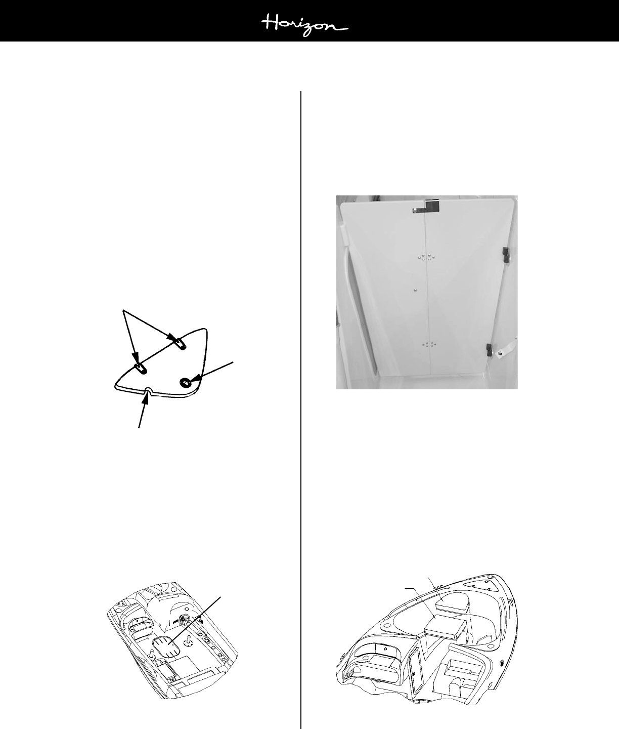
Section K
Page 2
180/190/200 Horizon
Owners Manual
08/01
K - 5 ANCHOR LOCKER STORAGE
All Horizons® have a built-in anchor locker. It is lo-
cated at the bow of the boat. Simply lift the anchor lid
at the pull handle to gain access to the anchor locker
on the Horizon® 190 and 200 or remove the center
bow cushion to gain access to the anchor storage on
the Horizon® 180.
For those models with an anchor lid, a notch has been
incorporated which allows the anchor line to pass
through while the anchor lid is closed. See Figure K3.
The anchor locker has an overboard drain to remove
any water that might otherwise accumulate. The com-
partment should be inspected after each use and kept
clean of dirt and debris to prevent plugging of the drain
hole. For information on anchors, refer to Section L-5.
Figure K3: Horizon® Anchor Locker
K - 6 SKI STORAGE LOCKER
A standard feature on all Horizon® models is an in-
floor ski locker. The locker allows for storage of skis,
knee boards, tow ropes, personal floatation devices,
etc. The ski storage lid is hinged for ease of use and
will stay in place in choppy water. See Figure K4.
Figure K4: Horizon® Ski Locker
K - 7 WALK-THRU DOOR
An optional walk-thru door is available on all Horizon®
models. The walk-thru doors are designed to keep out
the wind and weather, making for a warmer cockpit area.
Please contact your Four Winns dealer if interested in
adding this option. See Figure K5.
Figure K5: Horizon® Walk-Thru Door
K - 8 BOW FILL-IN CUSHIONS
With the optional bow fill-in cushion(s) you can turn the
bow of your Horizon® into a sundeck. These bow fill-in
cushions can be easily removed or installed in a matter
of minutes. The bow fill-in cushions may be stored ei-
ther under the starboard consoles or in the side wall
storage locker. Contact your Four Winns dealer who
will be glad to order them for you.
Figure K6: Horizon® Bow Fill-Ins Cushions
Hinges
Pull Handle
Flush Mount
Notch for Line
Ski Locker Lid
Bow Fill-In
Forward Cushion
Bow Fill-In
Aft Cushion

Section K
Page 3
180/190/200 Horizon
Owners Manual
08/01
K - 9 WALK-THRU STORAGE LOCKERS
On the 200 Horizon® model only, generously sized
walk-thru storage compartments are included as stan-
dard features. Personal floatation devices (PFDs) along
with other types gear can be easily stored in these stor-
age compartments. They are located in the helm and
passenger consoles of the walk-thru area. See Figure
K7.
Figure K7: 200 Horizon® Walk-thru Storage
Storage Locker
w/ Access Door

Section L
Page 1
180/190/200 Horizon
Owners Manual
08/01
EXTERIOR EQUIPMENT
L - 1 RAILS & DECK HARDWARE
A. Rails
Grab handles have been installed to provide security for
passengers in the cockpit. Limiting passenger move-
ment while underway is recommended. All those on
board should be safely seated whenever possible. Ad-
ditional care must be taken when in rough seas or foul
weather.
The rail system and hardware fittings have been selected
and installed to perform specific functions. Fenders or
mooring lines should not be secured to the rails or stan-
chions. Be certain that a clear lead exists when running
dock lines or an anchor line. A line inadvertently threaded
around a stanchion or over the rail could cause damage.
B. Cleats
The cleats that have been installed are specifically de-
signed and are intended to be used as mooring cleats.
Their purpose is for securing the vessel to a dock, pier,
mooring, or anchor.
FourWinns® Boats are not equipped with any
hardware designed for towing purposes. The
mooring cleats that are installed on the boat are
not to be used for towing another vessel or hav-
ing the boat towed. Refer to Section A - Opera-
tion for additional precautions regarding ground-
ing and towing.
C. Stern Rail with Ski Tow Ring
The ski tow ring has been incorporated into the stern
grab rail and is mounted on the transom above the inte-
grated platform. See Figure L3. It is available on all
models. All these models should pull two skiers under
normal boating conditions. However, Four Winns rec-
ommends no more than two skiers be pulled behind the
boat at any time.
Do not use ski tow fitting for lifting or parasail-
ing. Fitting could pull out of deck resulting in
serious injury or death.
To prevent personal injury or damage to the boat,
DO NOT tow more than two water skiers with
the transom mounted ski tow fitting.
NOTICE
Skiers weight, boating conditions, amount of
gear, and operators experience will affect the
number of skiers which can be pulled.
D. Maintenance
The majority of the hardware installed is made of stain-
less steel. Regardless of the type of hardware used,
periodic maintenance is necessary.
The manufacturer of our hardware recommends the fol-
lowing when washing your boat:
1. Rinse the hardware with fresh water after each ex-
posure to saltwater.
2. Periodically wash the hardware with mild soap, warm
water, and a sponge. Then dry it with a soft cloth.
3. Avoid cleaners, abrasives, waxes, and most of all,
do not use steel wool.
NOTICE
All fittings must be periodically inspected for loos-
ening, wear, and damage. Problems should be
corrected immediately!
L - 2 WINDSHIELDS
The windshield on all Horizon models is standard equip-
ment. Windshields consisting of tempered safety glass
and the windshield frame consists of a powder coated
aluminum. For easy accessibility to and from the bow,
a walk-thru center windshield is standard. Stainless
steel supports or braces are used in all of the wind-
shield assemblies.

Section L
Page 2
180/190/200 Horizon
Owners Manual
08/01
Swim Platform
Ladder Lid
Swim Ladder
Ladder Hinge
Stern Rail w/ Ski Tow
Figure L2: Swim Ladder
Keep hands and fingers away from ladder hinges
and the space between the ladder and swim
platform to prevent injury.
NEVER APPROACH OR USE LADDER
WHEN THE MOTOR IS RUNNING. SEVERE
INJURY OR DEATH WILL RESULT FROM
CONTACT WITH ROTATING PROPELLER.
Shut off motor when near swimmers. Severe
injury or death will result from contact with ro-
tating propeller or exposure to carbon monox-
ide gas.
NOTICE
Always secure the ladder before boating.
Damage to the ladder may otherwise result.
To prevent personal injury, swim platform and
transom entry area must not be occupied while
engine(s) are running.
L - 4 ADD-ON SWIM PLATFORM OPTION
An optional add-on swim platform is available for cur-
rent Horizon® models. The platform extends the exist-
ing swim platform creating more space for water sport
activities. See Figure L3. This is a dealer installed
option. Please see your Four Winns dealer for details
on ordering this popular option.
NOTICE
Make sure walk-thru is closed and secured when
boating. Damage to the windshield will other-
wise result.
Windshields made of tempered glass can be cleaned
with automotive glass cleaners or dishwashing soap and
water. Use a clean cloth to prevent scratching the glass.
Aluminum can be cleaned with similar products or with
nonabrasive cleaners such as Fantastik.
NOTICE
Read the label before using any product. DO
NOT use abrasive cleaners.
L - 3 SWIM PLATFORM - STERN LADDER
FourWinns provides a newly designed swim platform
with integrated toe rail for better footing. To also assist
with footing, a skid-resistant surface is provided. The
swim platform is recessed for the ladder and a hinging
ladder lid is provided. With this design, the ladder is
concealed and you do not lose valuable platform space.
See Figure L1.
Figure L1: Swim Platform
The ladder is deep and angled mounted which makes
it easier to climb. Its starboard location means youre
not approaching a down skier on your blind side. See
Figure L2.

Section L
Page 3
180/190/200 Horizon
Owners Manual
08/01
L - 5 ANCHOR & ANCHORING
Anchors are available in different shapes, sizes and
weights to fit different boats, uses, and conditions. The
weight of the anchor and diameter of anchor line should
be governed by the size and weight of your boat. Four
Winns recommends a Danforth style 8 pound,
Attwood® Penetrating anchor, with a 3/8 line be used
on all the 180-200 Horizons® models. The recom-
mended line length is 100-150 feet. Because of differ-
ences in style, a larger anchor may be needed for differ-
ent bottom or boating conditions. Your Four Winns
dealer can tell you which anchor will work best for your
boat.
Keep anchor secure while underway to prevent dam-
age or injury due to sudden shifting in the boats atti-
tude.
Use two or more anchors if anchoring overnight or for
extended periods. If not using two anchors, make cer-
tain there is sufficient clearance for your boat to swing
in a full circle to prevent damage in case of shifting
winds.
Make certain you have enough anchor line (or scope)
for the depth of water. Your anchor line should be 6 to 7
times the depth of water anchored in. For example, if
you are in 20 feet of water, use 120 to 140 feet of an-
chor line.
Swim Platform
Figure L3: Add-On Swim Platform
Secure anchor line to bow eye or deck cleat.
Never tie anchor line to a rail, rail fitting or other
hardware not designed to support this stress.
To drop anchor:
Approach your selected anchoring site from downwind
and come to a dead stop over the spot where you want
to drop anchor. Lower the anchor.
Maneuver the boat slowly backwards until length of
anchor line is 6 or 7 times the depth of the water.
Fasten the anchor line around the bow eye or deck
cleat. Anchor flukes should dig in and catch. Watch for
anchor drag by checking shoreline landmarks at the
time the anchor is dropped and one-half hour later. If
the boat has drifted away from these reference marks,
the anchor is dragging and must be reset.
To weigh anchor:
Start the engine running before pulling in anchor.
Slowly maneuver the boat forward to reduce tension
on the line and make retrieval of the anchor line easier.
Raise and secure the anchor.
Always be sure to raise and secure the an-
chor prior to operating your boat. Failure to
raise and secure anchor before getting under-
way could result in damage to boat and even
severe injury or death from a rebounding an-
chor.
If the anchor becomes stuck, attach the vertical line to
the mooring cleat. Wave action on the bow may lift
flukes from the bottom and free the anchor. If the an-
chor is still stuck, feed out a few feet of line and attach
it to the bow cleat. Maneuver the boat around the an-
chor, keeping the line firm. Determine the angle that
will work to pull the anchor free.
Anchors are usually a dealer installed option. Please
check with your Four Winns® dealer for recommenda-
tions.

Section L
Page 4
180/190/200 Horizon
Owners Manual
08/01
L - 6 DEPTHSOUNDER
The depthsounder is standard equipment on all the
Horizon® models The depthsounder has both audible
and visual alarms. See Section E-6H of this manual
for additional information regarding the operation of the
specific depthsounder for your Four Winns® model.
Do not rely on depthsounder to avoid sub-
merged objects. Depth sounders provide a rela-
tive indication of water depth only.
NOTICE
DO NOT depend solely upon the depthsounder
for water depth. It is important to have
navigational charts of the waters in which you
are operating.
L - 7 WAKE BOARD TOWER - (190H/200H Only)
The 190-200 Horizon® models have an optional wake
board tower available. See Figure L4. The towers
come with a variety of features which will sure to please
the wake board enthusiasts. Please see your Four
Winns dealer for information regarding this option. Re-
fer to Section B-4 - Water Sports of this manual for
safety guidelines.
Figure L4: Wake Board Tower
Do not use ski tow fitting for lifting or parasail-
ing. Fitting could pull out of deck resulting in
serious injury or death.
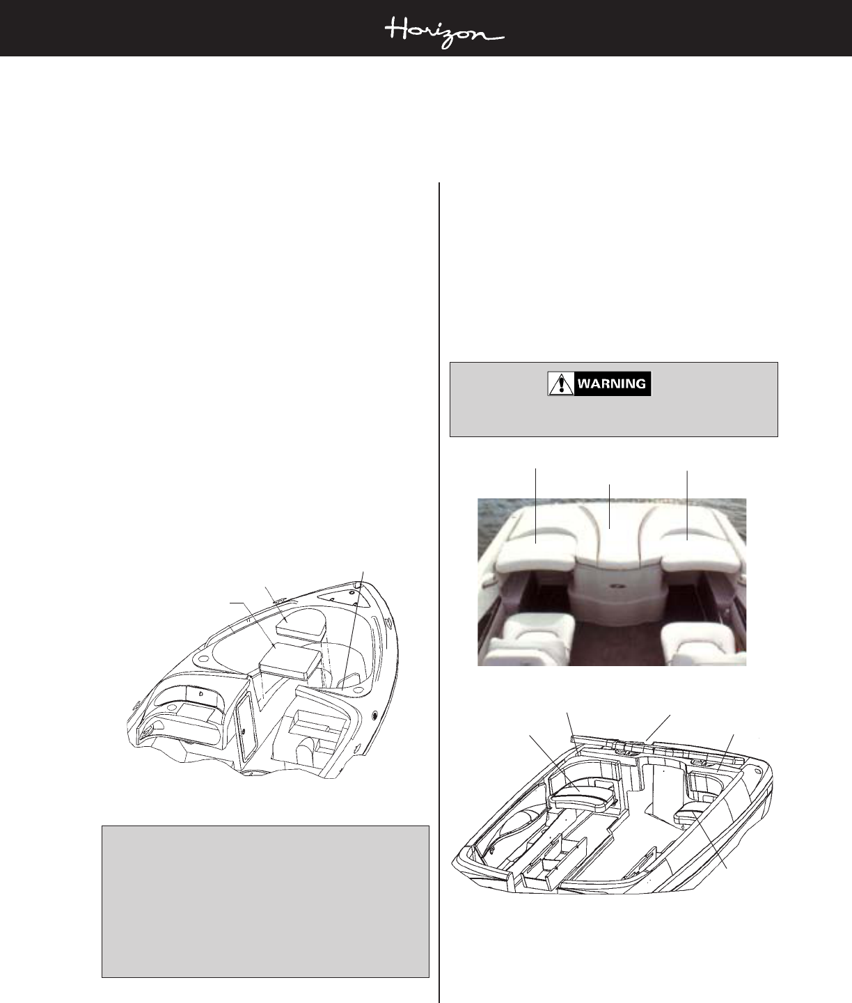
Section M
Page 1
180/190/200 Horizon
Owner’s Manual
08/01
C. Jump Seats
The 180-200 Horizon® models come equipped with
adjustable jump seats. These jump seats can be placed
in either a raised or lowered position. In the raised
position and in conjunction with the top storage, it makes
a roomy sun lounge. See Figure M2. Lowered, they
become jump seats. See Figure M3. If needed, the
jump seats can be removed to create additional floor
space.
DO NOT allow passengers to sit on jumpseats
in raised position while underway.
Figure M2: Jump Seats in “Raised” Position
Figure M3: Jump Seats in “Lowered” Position
M - 1 EXTERIOR SEATING
A. Cockpit Tables
An optional cockpit table with a flush mount is available
on the 190 and 200 Horizon® models. Rotating the
table top while lifting will ease the removal of the table
from the leg. Table legs are removable for easy storage
by unscrewing the leg from the flush mounted floor base.
B. Bow Seating
Bow seating is provided on the Horizon® models. Cer-
tain cushions have hinges to allow for access to storage
areas below.
Bow fill-in cushions are optional on the Horizon®. When
installed, the fill-in cushions help form a sundeck across
the bow area. These cushions may be stored in the
area beneath the passenger console with a strap or in
the walk-thru storage. See Figure M1.
Figure M1: Horizon® Bow Fill-Ins Cushions
NOTICE
When traveling at highway speeds, be sure the
fill-in cushions are properly secured (locked in
position). Air currents (created within the inte-
rior when traveling) will lift the cushions up and
out of the boat under certain conditions; espe-
cially when semi-trucks or other large vehicles
pass by.
UPHOLSTERY
Bow Fill-In
Forward Cushion
Bow Fill-In
Aft Cushion
Bow Storage
Compartment
Top Storage
Starboard
Jump Seat
Port
Jump Seat
Top Storage
Starboard
Jump Seat
Port
Jump Seat
Backrest
Backrest

Section M
Page 2
180/190/200 Horizon
Owner’s Manual
08/01
In addition, the “adjustable” lounger is adjustable for-
ward and back. To adjust, turn the handle upwards and
push/pull the seat assembly. The total travel distance or
adjustment is approximately six (6) inches.
E. Top Storage
The top storage compartment at the stern of the boat
allows for storage of the convertible canvas top assem-
bly. The top storage is secured by a latch mechanism.
A spring stay keeps the top storage in the raised posi-
tion while storing gear or for maintaining the engine.
Figure M6: Top Storage
To open the top storage compartment :
Locate the strap and pull to release the latch.
Lift upward until the spring lid locks the top storage
cushion in the open position.
To close the top storage compartment :
With one hand holding the top storage cushion, use
the other hand to bend the spring stay.
Lower the top storage gently into the closed position.
Place both hands on top of the cushion directly over
the latch mechanism and push down to ensure the latch
engages the striker.
NOTICE
When traveling at highway speeds, be sure the
jump seat cushions are properly secured in the
lower position. Air currents (created within the
interior when traveling) will lift the cushions up
and out of the boat under certain conditions; es-
pecially when semi-trucks or other large vehicles
pass by.
D. Lounger
The standard seating configuration on the 180-200
Horizon® models includes port and starboard “back-
to-back” lounger seating. See Figure M4.
Figure M4: “Back-to-Back” Loungers
The loungers consist of two major components. These
components are the lounger backrest and the lounger
seat cushion. The lounger has been designed so that
each component is serviceable. See Figure M5.
Figure M5: Lounger Assembly
The “adjustable” lounger can be placed into either an
upright position (Figure M5 above) or a reclining posi-
tion. A locking hinge on the end will allow for a “kickup”
headrest to be created when in the reclining (lounge)
position. Refer to Figures M11 & M12 at the end of this
section for drawings on lounger operation.
Backrest
Cushion
Top Storage
Strap
Latch

Section M
Page 3
180/190/200 Horizon
Owner’s Manual
08/01
operating the boat. Depending upon which model you
have, the bucket seats may be limited in the amount
and direction of swivel possible.
The bucket seat also comes with a flip-up bolster. By
simply flipping up the bolster the driver is able to sit
higher in the seat. This is designed to give the driver
and passenger greater flexibility, increased visibility, and
riding comfort.
NOTICE
The bucket seats may or may not rotate com-
pletely 180
o
. The amount and direction of
swivel available depends on the model you
have.
NOTICE
When rotating the bucket seat, damage to seat,
steering wheel (if applicable), and/or coaming
pad may result if attempting to rotate in the
wrong direction or over-rotating. DO NOT USE
FORCE to rotate the chair.
To rotate the bucket seat to face the aft position:
1. Tilt the steering wheel (if applicable) as far forward
as possible.
2. Slide the seat completely forward or rearward (as
needed to clear coaming/side pad) by using the
lever located underneath the seat, at the center.
See Figure M8.
3. Locate the lever on the left side of the buckets slider
mechanism and pull to release the pin from the
pedestal. This will allow you to rotate the seat. The
seat may or may not allow a person to rotate the
seat while being seated. See Figure M8.
4. Rotate the bucket seat inboard (towards the cen-
ter of the boat) until it faces as far aft as possible.
To return the bucket seat to the bow facing position:
1. Slide the seat completely forward or rearward (as
needed to clear coaming/side pad) by using the
lever located underneath the seat, at the center.
See Figure M8.
2. Locate the lever on the left side of the buckets slider
mechanism and pull to release the pin from the
pedestal. This will allow you to rotate the seat. The
seat may or may not allow a person to rotate the
seat while being seated. See Figure M8.
Friction Adjustment Knob
Pull release handle up to
move forward and back.
Pull lever up to release
pin from pedestal to
swivel bucket seat.
NOTICE
Never operate your boat with the sundeck and
or top storage in their open position. Doing so
could result in damage or loss of cushion and
hardware. This is also true when trailering your
boat. Cushions, if not properly stored and
secure, will blow out of the boat.
F. Bucket Seats (Sunsport Seating Option)
The adjustable bucket seats are included on all Sunsport
seating configurations for 180-200 Horizon® models.
See Figure M7. To adjust, lift up on the metal release
handle under the middle of the seat. Slide the seat for-
ward or aft to the desired position. The seat will adjust
approximately six (6) inches. See Figure M8.
Figure M7: Sunsport Seating
Figure M8: Bucket Seat Slider Base (Front View)
Both bucket seats are also designed to swivel. This
permits the spotter to be in the proper position to watch
water-skiers or allows the driver to socialize when not

Section M
Page 4
180/190/200 Horizon
Owner’s Manual
08/01
3. Rotate the bucket seat inboard until it locks into the
forward facing position. In addition, DO NOT USE
FORCE to rotate the chair.
4. Position the seat forward or aft according to the
needs of the individual by using the lever located
underneath the seat, at the center. See Figure M8.
5. Tilt the steering wheel (if applicable) to the desired
position using the tilt lever knob on the steering col-
umn.
DO NOT sit on the backrest portion of any cock-
pit seat. The operator could lose control of boat
or passengers could be thrown from boat. Also,
the seat may be damaged from improper use.
G. Sundeck (Sunsport Seating Option)
On the Horizon® Sunsport models, the sundeck is one
complete piece that runs the entire width (beam) of the
boat. The sundeck can be used for sunbathing and is
supported by bulkhead and other supports. It is secured
by a latch mechanism. A gas shock or hydraulic sup-
port assists in raising the sundeck and keeps the
sundeck in the raised position while storing gear or for
maintaining the engine. See Figure M9.
To lift the sundeck, pull the strap of the sundeck cushion
latch and lift up the sundeck using your other hand.
To close the sundeck, lower the sundeck gently into the
closed position. Place both hands on top of the cushion
directly over the latch mechanism and push down to
ensure the latch engages the striker.
Figure M9: Sundeck Assembly
NOTICE
Never operate your boat with the sundeck and
or top storage in their open position. Doing so
could result in damage or loss of cushion and
hardware. This is also true when trailering your
boat. Cushions, if not properly stored and
secure, will blow out of the boat.
H. Sunsport Couch
The couch assembly is part of the optional Sunsport in-
terior. On all sunsport models the bench seat slides out
to create additional berthing or sunbathing space. A
shock cord is attached to the couch cushion and a
bungie knob is placed on the couch support base. Loop-
ing the shock cord around the knob will prevent the
couch from accidentally sliding out when running in
choppy water.
Figure M10: Couch Assembly
M - 2 EXTERIOR UPHOLSTERY CARE
The vinyl material used on the exterior upholstery can
be easily cleaned using mild detergent and water. Be
sure to thoroughly rinse the seats after washing to re-
move all soap film. Periodic spraying of the seats with
Lysol Spray Disinfectant™ will help retard mildew.
NOTICE
DO NOT apply vinyl protectants such as
Armoral™. The manufacturer does not recom-
mend this product because it removes the oils
present in vinyl that keeps vinyl soft.
A recommended “Cleaning Kit” includes:
• Ivory Dishwashing Liquid™ and water
• Clean, white towels
• Medium-soft brush
Sundeck
Strap
Shock Cord
Bungie Knob

Section M
Page 5
180/190/200 Horizon
Owner’s Manual
08/01
• Fantastik Spray Cleaner™
• Denatured Alcohol
• Tough Duty Cleaner™
(to locate the nearest distributor, call 800-537-8990)
• Ammonia and hydrogen peroxide
To remove stains, follow the guidelines below.
1. Basic Stains/Grease/Pencil/Dirt:
Ivory Soap and water or Fantastik Spray Cleaner™
applied with a medium-soft brush.
2. Tough Stains/Adhesive/Teak Oil/Rust:
Tough Duty Cleaner™; rinse with soap and water.
NOTICE
To prevent possible damage to the vinyl, rinse
with soap and water after applying the Tough
Duty Cleaner™.
3. Ink:
Denatured alcohol.
4. Mildew Stains:
To kill bacteria creating the mildew, vigorously brush
the stained area with a 4-to-1 mixture of water and
ammonia; rinse with water.
5. Tough Mildew Stains:
Apply a mixture of one (1) teaspoon ammonia, one-
fourth (1/4) cup of hydrogen peroxide, and three-
fourths (3/4) cup of distilled water; rinse with water.
NOTICE
ALWAYS CLEAN STAINS IMMEDIATELY! DO
NOT use 409 Cleaner™ or Armorall™ on vinyl.
All cleaning methods must be followed by a
thorough rinse with water.
Certain household cleaners, powdered abrasives, steel
wool and industrial cleaners can cause damage and dis-
coloration and are not recommended. Dry cleaning flu-
ids and lacquer solvent should not be used as they will
remove the printed pattern and gloss. Waxes should
be used with caution. May contain dyes or solvents that
can permanently damage the protective coating.
Additional cleaning information is provided by the manu-
facturer and is included with this manual.
Four Winns offers a variety of optional weather covers
for protection of the boat and associated equipment. Con-
tinued exposure can damage the upholstery and seat-
ing. The seating can become thoroughly saturated with
water if not adequately protected. Refer to Section N -
Weather Covers for more information.
NOTICE
The appearance and longevity of the exterior
upholstery will be affected by water saturation.
Protect these items appropriately.
M - 3 REPLACEMENT UPHOLSTERY
Should upholstery become severely soiled, torn, or in
some manner damaged, replacement upholstery cush-
ions are available. Larger upholstery items have sepa-
rate component parts for easier serviceability.
Depending upon the year and model of the boat, most
upholstery parts can be obtained through your Four
Winns® servicing dealer within a short period of time.
M - 4 CARPET CARE
A. Interior and Exterior Carpet
Four Winns® boats use a high quality grade carpeting in
the cabin and cockpit. Vacuuming and occasional rug
shampooing are recommended for extended life and ap-
pearance. It is 100% UV stabilized Olefin™ Polypropyl-
ene fiber.
The optional snap-in carpet for the cockpit with fiberglass
liner is also made of 100% UV stabilized Olefin™ Polypro-
pylene fiber. This is an exterior grade, high quality car-
pet with rubber-type backing.
NOTICE
DO NOT dry carpeting in an automatic dryer.
The snap-in carpet may be periodically washed with mild
laundry soaps or shampooed, dried and reinstalled. Ad-
ditional information is listed below.
B. Cleaning and Maintenance
The following information should be useful in helping you
keep your carpet looking well maintained.

Section M
Page 6
180/190/200 Horizon
Owner’s Manual
08/01
STAIN REMOVAL PROCEDURE
Automotive Grease A
Automotive Oil (New or Used) A
Bacon Grease A
Berry Stain A
Blood A
Butter A
Catsup or Mustard A
Chewing Gum A, B (Repeat)
Chlorine Bleach (5%) A
Chocolate (Melted) A
Clay (Red) A
Coffee or Tea A
Cola A
Crayon A, B, C
Egg A
Feces A
French Dressing A
Furniture Polish A
Table I: Stain Removal
Carpet made with Olefin™ fiber possesses built-in stain
and soil release for easy, less costly maintenance. Regu-
lar vacuuming and occasional shampooing help it stay
attractive and serviceable.
C. Stain Removal Testing
Even the most stubborn stains can be removed from
Olefin™ fiber following the procedures outlined. A total
of thirty-four stains were selected as being representa-
tive of spills commonly occurring on carpets. Stains were
pressed into the carpet to simulate foot pressure follow-
ing a spill. Stains were applied to a two-inch square
section and allowed to penetrate. Removal was per-
formed after two weeks. Carpets were tested for stain
removal by an independent laboratory. Stain removal
was effective for all 34 stains. Results are shown in the
table.
D. Stain Removal Procedure
Regular maintenance such as vacuuming, hosing or
washing should be performed. Most stains and mildew
are easily removed from carpet made with Olefin™ fiber
using common household cleaners. Refer to Table I.
Olefin™ fiber is so resistant to chemical attack that Clorox
Bleach™ may be used to clean up any mildew that may
result from excessive wetness.
Code for stain removal procedure (See Table 1):
“A” Apply hot water and detergent.
“B” Apply volatile dry solvent, work with bone spatula,
blot.
“C” Flush by hot water extraction.
Recommended reagents:
• Carpet detergent such as Mintex™ (Hydromaster®)
or any carpet detergent suitable for hot water ex-
traction.
• Volatile dry solvent such as Carbona™, Energene™,
or Picrin™ (Street®).
• Oily type paint remover such as nail polish remover,
Energene™ or Pyrotex™ (Street®).
• Neutral lubricant such as Streetex Spray Spotter™
(Street®) or alternate treatment with detergent and
Energene™.

Section M
Page 7
180/190/200 Horizon
Owner’s Manual
08/01
Figure M12: Steps to change lounger to the “up” position.
Figure M11: Steps to change lounger to the “down” position.

Section N
Page 1
180/190/200 Horizon
Owners Manual
08/01
N - 1 GENERAL INFORMATION
Weather covers for the cockpit areas are available on all
Horizon® models. Convertible and bimini tops, side and
aft curtains, mooring, and cockpit covers are available.
(Note: Canvas options availability vary depending on
which model you have. Please consult your Four Winns
dealer regarding canvas availability for your particular
model.) Four Winns® covers are designed and intended
to provide protection of the cockpit seating areas.
Four Winns utilizes acrylic-type material for all its cov-
ers. All Horizon® canvas, with the exception of moor-
ing covers, consist of 100% acrylic material and is color
matched to the boat. The mooring covers are made of
10 ounce acrylic and come in dark gray only.
Never use any form of open flame cooking de-
vice while under, in any area fully enclosed, or
near any acrylic weather cover. This material is
flammable.
During the manufacture of the weather covers, the small-
est possible needle and highest quality UV stabilized,
bonded polyester thread is used in the stitching.
The weather cover is water repellant but not water proof.
During a hard rain, you may notice a light mist permeat-
ing through a weather cover. This is normal. If the seams
leak, they can be sprayed with Scotchguard or similar
water repellent or a seam sealing compound can be
applied. Keep objects from contacting the inside of the
cover. Leakage may occur at point of contact.
Weather covers must be installed taut or will be dam-
aged by accumulation of rain water.
NOTICE
Periodically check weather covers for accumu-
lation of water. Damage to the bow assemblies
may otherwise result. Make sure cover is taut
to avoid puddling of water.
After use, the top canvas should be rolled up into the
boot (if supplied) and secured.
NOTICE
NEVER fold or store a wet weather cover. This
can lead to mildew or shrinkage. Roll rather
than fold the enclosure curtains. Sharp folds
increase the chance of cracking the clear vinyl.
NOTICE
DO NOT use the weather covers during out-
door winter storage. The weight of the snow or
heavy rain can cause severe damage to the
material or top structure. Refer to N-3 - Winter
Storage in this manual for more information.
When snapping covers to the boat, apply direct down-
ward pressure on the snap. When unsnapping, rotate
the snap and cover upward at each snap location.
NOTICE
Remove snaps one at a time to prevent dam-
age. DO NOT rip off or pull the weather cover
as a whole; acrylic material may tear at snaps.
A. Convertible Top (Suntop)
On the 180, 190 and 200 Horizon® models, a convert-
ible top is available. It covers the cockpit area and is
stored in the rear engine compartment, under the top
storage. A canvas boot is provided which is used to
encase the suntop for storing.
To install:
1. Attach the main bow to the windshield mount and
unroll the canvas.
2. Snap the forward edge of the top to the windshield.
Windshield snaps will slide to adjust to the canvas.
NOTICE
The center snap should be centered on the wind-
shield, then adjust all other windshield snaps to
align to canvas snaps.
WEATHER COVERS

Section N
Page 2
180/190/200 Horizon
Owners Manual
08/01
3. Adjust the secondary bow to support the canvas and
attach the nylon strap to the strap eye located on
the deck. The strap can be adjusted for tautness.
NOTICE
On the Horizon® models, couplers on the bow
extensions allow for vertical adjustment. Hori-
zontal adjustments can be made with the buckle
located on the nylon strap and by sliding the
secondary bow(s) up or down along the main
bow.
B. Side Curtains
The side curtains are used to enclose the area between
the windshield wings and canvas. Each curtain will zip
to the underside of the suntop and snap to the wind-
shield wings. Windshield snaps will slide to adjust to the
curtain.
NOTICE
DO NOT FOLD THE SIDE CURTAINS! Dam-
age may result. Always roll the side curtains up
to prevent damage to the isinglass.
C. Aft Curtain
The aft curtain encloses the remaining cockpit area when
the suntop is installed. The aft curtain is part of the full
canvas option (which includes suntop and side curtains).
Refer to Figure N1.
Figure N1: Full Canvas
To install:
1. Attach the aft curtain to the zipper provided on the
rear portion of the suntop.
2. Secure the rear corners.
a. If the canvas has snaps along the aft edge, se-
cure the corners.
b. If the canvas has shock cords along the aft
edge, attach to knobs as shown in Figure N2.
Figure N2: Shock Cords
c. If the canvas utilizes a strap along the aft edge
of the aft canvas, place it around the ski tow
rail and snap it together.
3. Finish snapping canvas to deck.
When storing the aft curtain, roll the canvas which will
keep the isinglass from creasing.
D. Forward Cover
The forward cover is available on Horizon® models. It
is installed over the bow seating area and is snapped to
the deck. An adjustable pole is provided to adjust the
canvas for tautness and prevent the build up of water.
Refer to Figure N1.
E. Bimini Top (Southwest)
A bimini top is available on the Horizon® models. The
bimini top is a Southwest style which means it has
been extended to provide more protection from the sun.
The bimini top is a freestanding top and supported only
by the bow assembly. See Figure N3.
To install:
1. Attach the main (primary) bow to the windshield
mount.

Section N
Page 3
180/190/200 Horizon
Owners Manual
08/01
2. Attach the braces (aft of the main bows) to the deck
mount.
3. Open the canvas and support bows. Note: The
support bows should be loose to allow for adjust-
ment. Attached the forward straps to the forward
strap eyes which are also located on the deck, in-
side of the windshield.
Figure N3: Horizon® Southwest Bimini
4. Adjust the bows and straps for tautness.
You may choose to run your boat with the bimini top
either fully deployed or folded together (closed) and se-
cured with the boot provided. Either way it is designed
to remain mounted. No storage is provided for this top
in your boat.
NOTICE
If you desire to remove the bimini top (winter
storage), use two people. This will make the
storage process easier along with minimizing
any risk of injury. Using two people will help
prevent damage to the upholstery, the bimini
top, and/or the boat.
NOTICE
Bimini canvas deployment should only be uti-
lized at or below moderate cruising speed (ap-
proximately 0-45 mph). Avoid full throttle op-
eration of boat while having canvas deployed.
Four Winns recommends covering the canvas
with the boot cover before running at or close
to maximum speed. In so doing you will help
to maintain the life of the canvas and hardware.
Also, the wind should be taken into consider-
ation when determining operating speed with
canvas deployed.
F. Cockpit Cover
The cockpit cover is used to cover the complete cockpit
area and is intended as a short term storage cover. See
Figure N4.
To install:
1. Snap the forward edge of the cockpit cover to the
walk-through on the windshield. Windshield snaps
will slide to adjust to the canvas.
2. Secure the rear corners.
a. If the canvas has snaps along the aft edge, se-
cure the corners.
b. If the canvas has shock cords along the aft edge,
attach to knobs as shown in Figure N2.
c. If the canvas utilizes a strap along the aft edge
of the cover, place it around the ski tow rail and
snap it together.
3. Snap the cockpit cover sides and rear (if applicable)
to the deck.
An adjustable pole is provided to adjust the canvas for
tautness and prevent build up of water.
ter
Figure N4: Horizon® Forward and Cockpit Cover
G. Mooring Cover
Mooring covers are intended for longer term storage and
spread over the entire boat. See Figure N5. If used in
areas with snow accumulation, be sure to support the
canvas adequately and inspect frequently for snow loads
or damage will occur. Refer to N-3 - Winter Storage for
additional information.
Cockpit Cover
Forward Cover
Southwest Bimini
Primary Bow
Support Bow
Strap
Brace

Section N
Page 4
180/190/200 Horizon
Owners Manual
08/01
When storing outdoors, make sure the supporting frame-
work keeps the weight of the snow and rain from accu-
mulating on the storage cover. Proper ventilation must
also be provided or dry rot and mildew will occur. See
Section Q - General Maintenance for additional winter
storage information.
N - 4 MAINTENANCE
Moisture, dirt, chemicals from industrial fallout, heat, ul-
traviolet rays and in some cases, salt water are factors
which affect the longevity of acrylic covers.
1. Moisture can cause shrinkage and mildew. Allow
the cover to dry thoroughly before disassembling
tops. Keep it clean and well ventilated to prevent
mildew. Spraying the weather cover with Lysol
Disinfectant or similar product will help prevent
mildew.
2. Dirt creates a starting point for mildew when mois-
ture is present. Clean the top with a sponge or soft
scrub brush and mild detergent when the cover is
installed. Make sure cover is taut to help prevent
shrinkage.
3. Chemicals cause decay if allowed to accumulate
for long periods of time. Keep the cover clean to
prevent decay.
4. Heat can cause cracks in vinyl components and
stiffening of fabric when enclosed in plastic or poly-
ethylene. DO NOT store the weather cover in poly-
ethylene under direct sunlight or high temperature
situations.
5. Ultraviolet degradation may occur under prolonged
exposure to direct sunlight. Store the top in the boot
when not in use.
6. Salt water can corrode brass, aluminum, or stain-
less steel fittings and fasteners. Keep fittings clean,
lubricated, and waxed to prevent corrosion.
Clear vinyl curtains and windows demand extra care to
prevent scratching. DO NOT use cloth or chamois skin.
Dirt or grit in the cloth will scratch the vinyl window. Hose
clean water onto vinyl to rinse off salt, dirt, or grime.
To install:
1. Spread mooring cover over entire boat.
2. Install adjustable poles in bow area (if applicable) and
in the rear cockpit. Be sure the canvas is taut and no
pockets exist.
3. Tie off at the transom.
4. Nylon loops are provided for attaching rope or bungie
cords to the trailer or from side to side (under the
boat).
Figure N5: Horizon® Mooring Cover
N - 2 TRAILERING
High winds encountered during trailering your boat can
severely damage most weather covers. If an extended
trip at highway speeds is planned, the top and other
weather covers should be in the down position or removed
entirely. This will prevent damage and loss.
NOTICE
DO NOT tow your boat at highway speeds with
weather covers in place. High winds encoun-
tered during trailering your boat can severely
damage most weather covers. Damage to
weather covers incurred as a result of trailering
your boat is not covered under warranty.
N - 3 WINTER STORAGE
The boat must be properly protected during winter dry
dock storage. A winter storage cover is advisable. Many
marine dealers offer shrinkwrap enclosures for outdoor
storage. See a Four Winns dealer for information on the
availability of winter storage covers or other alternatives
for storage.

Section N
Page 5
180/190/200 Horizon
Owners Manual
08/01
NOTICE
DO NOT use hot water. DO NOT dry in an auto-
matic dryer. DO NOT dry clean or steam press.
Leakage after cleaning may be the result of insufficient
rinsing. Re-rinse. If leakage continues, apply a coat of
silicone air drying water repellent, such as
Scotchguard. See your Four Winns dealer for addition-
al information on weather covers.
N - 5 USE OF WEATHER COVERS AND CARBON
MONOXIDE
When an engine is running, a natural vacuum may exist
with the right wind and sea conditions to allow exhaust
gases (which includes carbon monoxide) to seap into
the boat. When the camper or side curtains are installed,
this compounds the possibility of this occurring and in-
hibits natural ventilation. For more information, refer to
Section B-2 - Carbon Monoxide in this manual.
The carbon monoxide in exhaust fumes can be hazard-
ous. It is important for you and your passengers to be
aware of the potential safety hazard created by exhaust
fumes. Familiarize yourself with the symptoms of indi-
viduals overcome by carbon monoxide, and most im-
portantly, ways you can protect yourself and your guests.
Exhaust fumes from engines contain carbon
monoxide. Boats with canvas deployed are
more likely to collect exhaust fumes. Avoid
brain damage or death from carbon monox-
ide. Keep cockpit and cabin areas well venti-
lated at all times. Signs of exposure include
nausea, dizziness, and drowsiness. See Sec-
tion B-2 of the boat owners manual for more
details. If using a catalytic heater, provide ven-
tilation. Do not use catalytic heater while sleep-
ing.

Section O
Page 1
180/190/200 Horizon
Owner’s Manual
08/01
Fiberglass cockpit liners and seat base are constructed
similar to the hull. Balsa core or coremat laminations
are utilized when necessary.
In addition to a thorough visual inspection of each fiber-
glass component, samples are measured using special
equipment, for fiberglass reinforcement to resin ratio,
laminate configuration, weight and thickness. By these
procedures Four Winns ensures proper composition.
O - 3 EQUIPMENT INSTALLATION
Many boats are used for specific purposes or under con-
ditions which require the addition of special equipment
to the hull or deck. Special care must be taken during
the installation of any equipment to a fiberglass com-
ponent. A polysulfide or butyl based sealant should be
used to seal installations below the water line. Silicone
“marine” seal or similar bedding compound should be
used elsewhere.
NOTICE
DO NOT install any item onto or through the
hull without adequately sealing the hull area
penetrated by the installed item or related fas-
teners. Improper installations could cause leak-
age or allow water absorption and thus cause
serious hull damage.
Always predrill fastening holes with a proper size
bit. Predrilling will help prevent the fiberglass
from splintering and thus causing unsightly dam-
age. Also, countersink holes to prevent the gel
coat from chipping.
Any equipment which will be subjected to cyclic loading
or significant force should be through-bolted to a fiber-
glass component. A butt block or backing plate should
be used to strengthen any area onto which an item will
be mounted. See your Four Winns dealer for assis-
tance.
O - 1 HULL DESIGN INFORMATION
Four Winns® boats are designed using the sound engi-
neering and mathematical principles of hydrostatics,
hydrodynamics, structure, and strength of materials. The
materials utilized provide optimum strength at the light-
est possible weight. The exact fiberglass laminate sched-
ule and construction techniques of each part is deter-
mined in accordance with the strength and rigidity re-
quired.
All Four Winns Horizon® models include our patented
Stable-Vee® hull design. Pods on either side of the
outdrive extend the running surface beyond the transom.
These pods, plus the unique distribution of deadrise from
transom to bow, allows Four Winns to place more hull in
the water than deep-vee designs of similar length and
beam. This results in better boat handling whether on
plane, during turns, or at rest.
O - 2 FIBERGLASS CONSTRUCTION
The fiberglass components of Four Winns® boats are
of the finest quality materials, workmanship and con-
struction techniques available. This ensures the struc-
tural integrity to provide years of boating enjoyment with
minimal maintenance.
The construction of a Four Winns® hull begins with the
application of gel coat to the mold. The gel coat is ap-
proximately 25 mils thick. A coat of resin and chopped
fiberglass is then sprayed into the hull and carefully hand
rolled until it is securely affixed to the gel coat.
A number of fiberglass layers and woven roving are ap-
plied to the above laminate. Each layer is hand laid and
hand rolled. The keel and chine areas have fiberglass
woven roving overlapped in these areas to provide addi-
tional strength. Some models utilize encapsulated
end-grain balsa core or coremat laminates to achieve
additional rigidity. Others utilize additional laminations of
woven roving to maintain strength and rigidity.
The hull support stringers are located using special tools,
and are fiberglassed into place. This ensures a strong,
rigid hull, permanently formed into a solid assembly, free
of distortions.
FIBERGLASS AND HULL INFORMATION

Section O
Page 2
180/190/200 Horizon
Owner’s Manual
08/01
O - 4 FIBERGLASS CARE & MAINTENANCE
Fiberglass is affected by weathering processes and re-
quires maintenance on a periodic basis to help maintain
the beauty and shine. The effects upon the gel coat will
be dependent upon boating conditions, storage, type of
use, and the care given to the boat during the boating
season.
Four Winns utilizes fade-fighting gel coat in the exterior
finish. It is specially formulated to resist fading and yel-
lowing, and retain more of its original gloss than better
grade gel coats. However, it is still important to maintain
the gel coat to protect the finish.
A. General Maintenance
For fresh water use, the boat should be washed once or
twice a month. When using in a salt water environment,
considerable more care will be necessary. Be careful
when selecting a cleaning agent. Hand dishwashing
detergents are usually gentle and are recommended for
cleaning gel coat. Cleaning products such as Ivory™ or
Dawn™ hand dishwashing liquid can be safely used.
Always read the label before using any product.
NOTICE
DO NOT use acetone, paint thinner, solvents,
or strong alkaline based detergents, nor clea-
ners with a “gritty” and abrasive texture. Avoid
products which contain sodium phosphate.
Common examples of these types of household
cleaning agents are: Tide™, Oxydol™, Janit-
or-in-a-Drum™, Fantastik™, Clorox™, etc. Al-
ways read the label before using an agent.
There are several products available which are specifi-
cally designed to clean fiberglass exterior finishes. Many
companies like Johnson & Johnson®, Turtle Wax®, etc.
manufacture cleaning fluids mild enough to clean with-
out stripping the wax.
NOTICE
Treading on a soiled fiberglass surface can se-
verely scratch and mar the finish. Keep the fi-
berglass as clean as possible.
When cleaning skid-resistant areas, DO NOT attempt
to use a wire brush or sandpaper because this will re-
move the skid-resistant gel.
Apply wax once or twice a year to maintain gel coat lus-
tre. Read the label before using any product. Make
sure product is formulated for gel coat surfaces. Also,
consult a Four Winns dealer for recommendations.
NOTICE
Do not use carnuba based waxes. This type
of wax yellows over time and makes the fiber-
glass appear yellow.
Waxing decks, cockpit floors or other walking
areas is not recommended. Waxing will pro-
duce a very slippery surface, especially when
wet. Wax may also buildup in the skid-resistant
surfaces. Be sure all persons wear deck shoes
while aboard the boat. Footing will be improved
and feet will be protected from accidental cuts
and bruises.
A darkening or discoloration of the skid-resistant surfac-
es can sometimes occur as a result of wax buildup. Expo-
sure to the sun and elements can turn the wax darker, or
occasionally can cause it to become flaky or powdery.
To remove, use fine rubbing compound and a low RPM
buffer (1200 to 2000 RPM). Apply light pressure and
keep the buffer moving at all times to prevent heat build
up. Read the directions before using any equipment.
B. Weathering Effects on Gel Coat
Weathering occurs from direct sunlight, water, chemi-
cals, and dust. Some of the terms below describe the
changes that can occur to the gel coat surface.
Chalking is a result of the gel coat’s top surface being
broken down into an extremely fine powder. When this
happens, the color whitens. The chalk is present on the
surface only.
Fading is the uniform change in color. This happens
when the actual pigments have changed color, espe-
cially from excessive chalking, or when the gel coat has
either been stained or bleached by something.
Yellowing is gel coat which has a yellow cast and strea-
king usually deals with a stain or contact with another
surface.
Gloss refers to the shine of the surface. This can change
from sanding action, chalk, residues, or exposure.

Section O
Page 3
180/190/200 Horizon
Owner’s Manual
08/01
Blistering refers to a condition in which the unprotected
gel coat surface below the waterline has absorbed wa-
ter and formed bubbles. See Section O-5 for additional
information.
Follow the instructions below for boats that have weath-
ered and chalked.
1. Wash.
2. Wax. If this does not work, then use a fine rubbing
compound. If this does not work use 400 or 600 wet
or dry sandpaper, followed by fine rubbing compound
and wax.
When using wax or fine rubbing compounds, make sure
to read the label and follow the directions. Some helpful
tips are listed below.
1. Avoid working in direct sunlight. This dries out the
wax or compound, and can stain the surface.
2. Use clean pads or cloths to apply a thin coating of
wax or rubbing compound to a small area such as
three feet by three feet. Remove any excess, and
then rub the area with a buffing pad, or power buffer.
Apply pressure only as necessary to restore the sur-
face finish.
Applying too much pressure or buffing
in one place too long can permanently damage the
surface.
3. After applying compound, always follow with wax-
ing.
NOTICE
If using a power buffer, use a low RPM buffer
with light pressure. Keep the pad wet and the
buffer moving at all times to prevent heat build
up.
NOTICE
To prevent gouges, uneven areas, or other dam-
age from occurring, DO NOT use a power or
belt sander when sanding. For best results,
block sand the gel coat.
C. Stains
Stains can appear anywhere on the exterior of the boat
and may be a result of contact with tar, plant sap, leaves,
rust from metal fittings, and other materials. Surface
stains may be removed with hand dishwashing soap,
mild cleansers, or some household detergents. DO NOT
use chlorine or ammonia products. These products can
affect the color of gel coat. Commercial car washes use
strong cleaners and should be avoided.
To remove stains, refer to the procedures below.
1. Wash area with hand dishwashing soap.
2. Begin with a small area such as three feet by three
feet and apply a mild cleanser.
3. Rinse with clean water.
4. Follow with compound and waxing as outlined in
procedure above.
If the stain is not removed by the hand dishwashing soap
or mild cleanser, then the next procedure is to use either
denatured or rubbing alcohol. If this does not work, con-
sult your Four Winns dealer for professional assistance.
NOTICE
DO NOT use acetone, ketone, or other solvents
to remove stains. These chemicals are flam-
mable and may damage the gel coat.
O - 5 FIBERGLASS REPAIRS
Fiberglass is one of the most durable, strong, and for-
giving construction materials afloat. It is resilient and
normal repairs can be made without affecting the strength
or structural integrity of the boat.
Striking docks, other boats, or submerged ob-
jects could create a very hazardous situation or
severely damage the fiberglass. In the event
an object is struck below or near the waterline,
proceed directly and cautiously to the nearest
service facility and remove the boat from the
water. Closely inspect the hull for damage. If
the outer fiberglass laminate was penetrated,
repairs must be made prior to relaunch.
Occasionally, blisters, crazing, scratches, or damage to
the fiberglass can occur. Repairs may be necessary to
correct the problem.

Section O
Page 4
180/190/200 Horizon
Owner’s Manual
08/01
6. After the gouge is filled and has dried, sand the
patched area. Begin by using medium-fine grade
sandpaper. Progressively use finer grade sandpa-
per until the surface is very smooth. If necessary,
add filler and then sand the surface again.
7. Apply two or three light coats of matching fiberglass
gel coat to the repaired area. Enough gel coat
should be used so that the entire area is covered.
The gel coat must be catalyzed using up to 2% MEK
Peroxide which can be purchased at a supplier han-
dling fiberglass reinforced products. Contact your
Four Winns dealer for assistance.
8. After ample drying time, sand the area using very
fine wet/dry sandpaper. If the appearance of the
area is still not satisfactory, repeat steps 2 through
8 as necessary.
9. If above the waterline, polish the area using a fiber-
glass rubbing compound and then wax. If the re-
paired area is below the waterline, the area should
be primed and painted in accordance with the anti-
fouling paint manufacturer’s instructions.
Gel coat, like paint, will change colors with time and
exposure to sunlight (ultraviolet). For this reason,
“matching” gel coat obtained from Four Winns may not
match the gel color of a boat that has been exposed.
However, this is the closest match commercially avail-
able. A fiberglass technician can tint the gel to be used
in the repair to provide a closer color match.
More severe fiberglass damage, especially when struc-
tural, requires the expertise of an experienced fiberglass
repair technician. See your Four Winns dealer for as-
sistance.
NOTICE
Improper repair techniques can lead to further
fiberglass component damag
C. Osmotic Blistering
Osmotic blistering or “boat pox” is an unfortunate but
not uncommon occurrence in fiberglass boats. Fiber-
glass is water retardant, not waterproof. When a boat
is left in the water for a period of time, the fiberglass will
absorb water. It is a natural process that can not be
eliminated in production methods or material selection
and usage. However, there are ways to control and
possibly prevent blisters (see Section O-6). If you do
A. Scratches
Scratches occur during normal use. Below is a step by
step procedure to repair scratches.
1. Clean area with soap and water.
2. Apply a fine rubbing compound and buff.
3. Wax.
If this does not work, clean the area and sand lightly with
400 to 600 wet or dry sandpaper and follow with rubbing
compound and wax.
B. Gouges & Cracks
Stress cracks and crazing are the appearance of hairline
cracks in the gel coat surface. When present, these prob-
lems usually occur in the gel coat finish or the outer “skin
coat” fiberglass laminate. The appearance of these
cracks does not pose a threat to the structural integrity of
the boat. In most cases, they are cosmetic and can be
treated.
Cosmetic surface damage can be repaired as follows:
1. Sand the surrounding area with medium or fine grit
sandpaper. Clean all marine growth, dirt, antifouling
paint, etc. from the immediate area. DO NOT ex-
cessively scratch or gouge the surrounding area.
2. Use a hard, pointed tool to open the gel crack. Take
care not to damage the surrounding gel coat.
3. Sand the crack or gouge so the edges are smooth
and will allow proper “feathering” of the area.
4. Clean the area thoroughly. Make sure the area is
dry before proceeding.
NOTICE
Be sure the structure and the ambient tempera-
ture are above 60 degrees F (15 degrees C) and
the relative humidity below 70% immediately
before, during, and after the repair.
5. If the nick or gouge is deep and penetrates through
the gel coat, fill the area with fiberglass patching paste.
Follow the directions on the can when mixing the
paste with the catalyst.

Section O
Page 5
180/190/200 Horizon
Owner’s Manual
08/01
encounter blisters, be assured that the blisters are merely
cosmetic. They do not indicate a defect in the boat struc-
ture or lamination. Four Winns, along with most boat
manufacturers, regard gel blisters as a standard main-
tenance item.
The repair procedure for gel coat blisters is similar to
the procedures outlined in the previous section on cracks
and gouges. There is an exception however, in that the
hull must dry out for several days or possibly weeks
before repairs can proceed.
To determine if the hull has dried sufficiently, tape one
square foot of household plastic wrap securely to the
hull bottom. Make sure all edges are sealed and let it
stand for twenty-four hours. If condensation has accu-
mulated under the plastic, the hull is still “wet” and must
be allowed to dry longer before repairing.
When the repair is completed, an application of an ep-
oxy barrier coat should be considered. This will help
prevent the possibility of reoccurrence of blisters. Your
Four Winns dealer or local ship store will have informa-
tion on barrier coat products.
O - 6 ANTIFOULING PAINT
Four Winns recommends antifouling or bottom paint for
boats which will be kept in the water for extended peri-
ods of time. Antifouling paint reacts with water to retard
the growth of algae, barnacles and other marine growth
on the hull. In addition to marine growth, it offers protec-
tion against excessive water pollution.
Antifouling paint begins reaction upon contact with wa-
ter. After a season’s use or sooner under certain condi-
tions, the antifouling paint may appear to be dissolving.
This is due to the paint’s chemical emission that in turn
retards marine growth. When this occurs, refinishing is
in order.
Four Winns recommends reapplication of the antifoul-
ing paint seasonally. The effectiveness of the paint will
be drastically reduced if used longer. Though
Four Winns has found the antifouling paints used to pro-
vide good marine growth protection in most water, other
paints may be more effective in certain water conditions.
See a Four Winns dealer for recommendations on anti-
fouling paint use in your area.
NOTICE
During surface preparation, the hull should be
sanded only enough to remove any foreign mat-
ter, and loose paint. DO NOT sand deeply into
the gel coat, fiberglass cosmetic problems could
later result. After sanding, the surface should
be wiped with a rag treated with a cleaner recom-
mended by the antifouling paint manufacturer.
The surface must be clean and slightly rough to
ensure paint adhesion.
Prior to application of the antifouling paint, the boat owner
may consider coating the hull bottom with an epoxy coat-
ing. Four Winns recommends this procedure as a pre-
ventive and effective means of controlling osmotic blis-
tering. Most major antifouling paint manufacturers also
supply a line of epoxy undercoatings. Consult your Four
Winns dealer for recommendations on epoxy undercoat-
ings.
O - 7 HULL SUPPORT
Proper support of the hull while it is out of the water is
imperative. Due to the design complexities, Four Winns
does not recommend use of home-made trailers or stor-
age cradles. The boat is a valuable piece of equipment.
DO NOT risk permanent damage to the hull structure in
an attempt to save the cost of an adequate support.
Improper support can lead to serious and permanent hull
deformation.
Failure to adequately support the hull may
result in permanent hull structure damage
and will invalidate the hull structure war-
ranty.
NOTICE
When attempting to raise the hull, never allow
one end of the boat to rise first, while letting the
opposite rest momentarily on the outdrives or
underwater gear. Serious damage to these com-
ponents could result. DO NOT place lifting straps
on underwater gear. Be sure the strap is against
the hull surface only.

Section O
Page 6
180/190/200 Horizon
Owner’s Manual
08/01
A trailer, or storage cradle designed for a larger or smaller
boat will not provide proper support for the hull. This could
lead to hull deformation and thus serious performance
deficiencies.
Four Winns® trailers are available for all Horizon® mod-
els. Refer to Section R - Trailers for additional informa-
tion.

Section P
Page 1
180/190/200 Horizon
Owners Manual
08/01
WOODWORK AND COMPOSITES
P - 1 HIGH-PRESSURE LAMINATE CARE
Table tops consist of a high pressure laminate, formica
like material. The formica has a matte texture finish
and can be cleaned with hand dishwashing soap and
water or other cleaning solutions such as Fantastik.
Always read the label before using any product.
NOTICE
DO NOT use abrasive cleaners or solvents on
formica. DO NOT use Soft Scrub soap or
similar cleaning products; they will scratch the
surface and remove the shine.
P - 2 STAR BOARD
Star Board is a high density polyethylene (plastic) and
is very durable and fade resistant. Star Board requires
little maintenance, and is being used in place of wood in
many areas of the boat. It is currently being used for ski
rack facers, ski locker lids, and seat supports.
To clean Star Board, use a solvent-free, nonabrasive
cleaner such as hand dishwashing soap or Fantastik.
Read the label before using any cleaning product.
NOTICE
Star Board will stain when exposed to certain
oils or chemicals. Always wipe up any spills
immediately.
P - 3 CHERRY ENHANCEMENTS
Cherry enhancements consist of a finished synthetic
cherry. This synthetic cherry is found in the instrument
dash panel of the helm and glove box on the Horizon®
models. In addition, the ignition switch panel and helm
switch panel, consist of this cherry.
To clean, a damp cloth will usually suffice.

Section Q
Page 1
180/190/200 Horizon
Owners Manual
08/01
Q - 1 WINTERIZATION
A. Prior to Lifting for Winter Lay-up
1. Have the fuel tank either full or completely empty.
See the Engine Owner's manual for recom-
mendations. Also, check with the dry dock opera-
tors for recommendations. If winter storing with a
full fuel tank, gasoline winterizer such as fuel condi-
tioner will reduce varnishing, condensation, etc.
NOTICE
If the fuel has been treated with winterizer, run
engines for ten minutes to make sure the treated
fuel is present in all lines and parts of the en-
gine.
2. Drain water from the fresh water system (if appli-
cable).
3. Winterize the engine and drive systems as recom-
mended in the Engine Owner's manual. Portions of
this winterization procedure may require that the boat
be lifted.
4. If the boat is to be lifted or taken off the trailer, see
Section O-7 Hull Support in this manual for addi-
tional details.
B. After Lifting
1. Remove the drain plug.
2. Thoroughly wash the fiberglass exterior, especially
the hull bottom. Remove as much marine growth
as possible.
3. Lower boat onto cradle properly or place boat on
trailer. Be sure boat is adequately supported. The
boat should be raised slightly under the forward sup-
ports or trailer tongue to improve drainage to the
transom drain.
4. Ensure that all water is removed from the bilge pump
and bilge pump lines. Dry the hull bilge, and
self-bailing cockpit drain troughs. Water freezing in
these areas could cause damage. See Section J-2
Hull Drainage Systems.
5. Remove the battery and store in a cool place. Clean
the battery using clear, clean water. Be sure the
battery has sufficient water and clean terminals.
Keep the battery charged throughout the storage pe-
riod. DO NOT store the battery on a concrete floor
or other damp or conductive surface.
6. Clean the interior of the boat thoroughly. Vacuum
and clean carpets.
7. Scrub the hull bottom and wash exterior fiberglass
components, wax lightly.
8. Clean exterior upholstery with mild soap and water.
Rinse and dry thoroughly.
9. Remove all oxidation from exterior hardware and
apply a light film of moisture - displacing lubricant.
C. Prior to Winter Storage
1. Remove as many cushions as possible. Remove
storage lids or hatches. Open as many locker doors,
as possible. Leave these areas open to improve
ventilation.
2. Spray the weather covers and the boat upholstery
with Lysol Spray Disinfectant. Enclosed areas
such as storage locker areas should also be sprayed
with Lysol Disinfectant.
3. Place small dishes of rodent poison such as D-Con
in a number of areas around the boat. Be sure dishes
are placed near the head and the engines, as ro-
dents will destroy upholstery, water intake and dis-
charge hoses.
4. If the boat will be in outside storage, properly sup-
port a storage cover and secure it over the boat.
DO NOT secure the cover tightly to the boat. This
does not allow adequate ventilation and can lead to
dry rot. DO NOT store the boat in a damp storage
enclosure. Excessive dampness can cause electri-
cal problems, corrosion, and dry rot.
GENERAL MAINTENANCE

Section Q
Page 2
180/190/200 Horizon
Owners Manual
08/01
5. DO NOT use the bimini top or camper top as a win-
ter storage cover. The life of these covers may be
significantly shortened if exposed to harsh weather
elements for long periods.
Placing an electric or fuel burning heating unit
in the bilge of the boat during cold weather could
cause fire or explosion and is not recommended.
NOTICE
Boats stored outside in areas with heavy snow
accumulation are more susceptible to damage,
and should be inspected regularly during the win-
ter months
6. Engine should be winterized according to
the engine manufacturers manual.
Q - 2 ENGINE FLUSH OUT
The optional engine flush out should be used to clean
the engine of unwanted salt, mud, sludge, etc. which
may have accumulated in the engine cooling system.
Before winterizing the engine, flush out the system for at
least five minutes.
Make sure that no section of flush hoses are in
contact with moving or hot engine parts or abra-
sive surfaces such as screw threads, sharp
edges, etc., which could damage the hoses.
Damage to the hoses could cause leaks and
possible flooding of the engine compartment.
Periodically check hoses for abrasions.
NOTICE
The flush out kit should only be used with the
boat in the water and the engine OFF.
To flush out the engine, follow the instructions below.
1. Do not run engine during flushing procedure.
2. Remove cap from coupling and attach swivel con-
nector.
3. Attach water supply hose to swivel connector.
4. Turn water on and allow water to flush the engine
and exhaust manifold for five to ten minutes.
5. Turn water off. Disconnect hose; replace and tighten
cap securely.
Reinstall cap onto coupler after flushing. Floo-
ding of the engine compartment will occur if the
cap is not installed and tightened.

Section Q
Page 3
180/190/200 Horizon
Owners Manual
08/01
Q - 3 GENERAL MAINTENANCE SCHEDULE
* Or as Required
Shaded areas indicate the time frame when service/inspection should be conducted.
SERVICE
AT LAUNCH
AND FIRST
OPERATION*
25 HOUR
CHECK EACH
SEASON*
BI-SEASONAL-
LY OR EVERY
6 MONTHS OR
EVERY 100
HOURS*
SEASONALLY
OR EVERY 12
MONTHS OR
EVERY 200
HOURS*
Engine and Instrumentation
Refer to Section E
Engine Maintenance
As Recommended by the Manufacturer
Inspect Exhaust System Hoses and Connections
Check Propellers
Check All Thru-Hull Fittings
Test Emergency Shut-Off Switch
Gauge Cleaning
Controls Systems
Refer to Section F
Throttle and Shift Adjustment
Neutral Safety Switch Test
Cable and Control Lubrication
Steering Systems
Refer to Section G
Linkage and Connection Inspection
Stern Drive Torque Tab Adjustment
Power Steering Service
As Recommended by the Manufacturer
Steering Adjustments
Steering System Lubrication
Electrical Systems
Refer to Section H
Inspect Battery Connections
Check Battery Water
Battery Cable Inspection
12 Volt Electrical Equipment Operation
12 Volt Wiring and Connection Inspection
Fuel System
Refer to Section I
Inspect for Leaks
Fuel Sender Inspection
Fuel Filter Inspection
Fuel Tank Inspection

Section Q
Page 4
180/190/200 Horizon
Owners Manual
08/01
* Or as Required
Shaded areas indicate the time frame when service/inspection should be conducted.
SERVICE
AT LAUNCH
AND FIRST
OPERATION*
25 HOUR
CHECK EACH
SEASON*
BI-SEASONAL-
LY OR EVERY
6 MONTHS OR
EVERY 100
HOURS*
SEASONALLY
OR EVERY 12
MONTHS OR
EVERY 200
HOURS*
Ventilation and Drainage
Refer to Section J
Blower Operation
Blower Vent System Cleaning
Bilge Pump Operation and Cleaning
Check Transom Drain Plug
Interior Equipment
Refer to Section K
Thru-Hull Fitting Inspection
Clean Cooler
Stereo Head Cleaning and Demagnetizing
Exterior Equipment
Refer to Section L
Check PFD’s for Serviceability and Correct Number
As Required
Check Charge of Fire Extiguishers
As Required
Check Compass for Magnectic Deviation
Upholstery
Refer to Section M
Clean Upholstery
Clean Carpet
Spray Upholstery with Lysol
Check Seat Hinges and Mounting Hardware
Weather Covers
Refer to Section N
Wash Weather Covers
Spray Weather Covers with Lysol
Fiberglass Components and Hull
Refer to Section O
Check All Fastenings (securing rails, seats, etc.)
Clean FiberglassThoroughly
Wax Hull Sides and All Non-Tread Areas
Inspect Fiberglass Areas for Damage
Perform Minor Touch-Up Repairs
Sand Hull and Re-Apply Anti-Fouling Paint
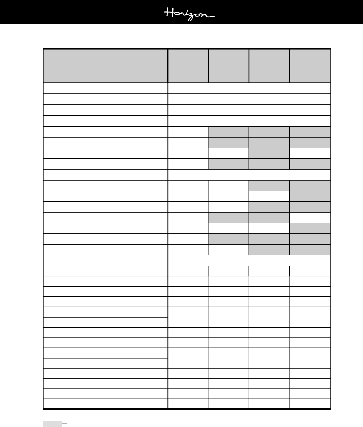
Section Q
Page 5
180/190/200 Horizon
Owners Manual
08/01
* Or as Required
Shaded areas indicate the time frame when service/inspection should be conducted.
SERVICE
AT LAUNCH
AND FIRST
OPERATION*
25 HOUR
CHECK EACH
SEASON*
BI-SEASONAL-
LY OR EVERY
6 MONTHS OR
EVERY 100
HOURS*
SEASONALLY
OR EVERY 12
MONTHS OR
EVERY 200
HOURS*
Woodwork & Composite Maintenance
Refer to Section P
Clean Star Board
As Needed
Clean Cockpit Tables
As Needed
Trailers Refer to Section R
Wax Trailer
Lubricate Trailer Jack
Lubricate Trailer Coupler
Lubricate Trailer Winch
Brake Operation
Before Every Use
Brake Inspection
Inspect Hubs/Disc Brakes
Inspect Bearings & Seals
Lubricate Bearings
Springs, Hangers & Suspension Parts
Wheel Lug Nut
Wheels
Tire Pressure & Condition
Before Every Use

Section R
Page 1
180/190/200 Horizon
Owners Manual
08/01
R - 1 GENERAL TRAILER INFORMATION
The trailer must properly match the boats weight and
hull design. Four Winns® trailers are designed specifi-
cally for each boat model. Four Winns® trailers meet or
exceed the National Marine Manufacturers Associations
trailer requirements.
Pulling a trailer affects the overall handling and
response time of your vehicle. ANTICIPATE
STOPS, BRAKE EARLY. Allow additional dis-
tance for stopping and turning.
Four Winns manufactures bunk type trailers. The bunks
are located specifically for Four Winns® boats and ad-
equately support all parts of the boat. It is a drive-on
type trailer which means winching the boat from the water
is not necessary.
NOTICE
When winching the boat onto the trailer, be sure
the bunks are wet to prevent damage to the
boat or trailer. DO NOT attempt to winch the
boat forward when out of the water. Damage to
the winch stand/assembly or tongue could oc-
cur.
Four Winns offers both painted and galvanized trailers.
The painted trailer is intended to be used in fresh water
and the galvanized trailer in salt/brackish water.
NOTICE
Four Winns does not recommend the usage of
painted trailers for salt/brackish water condi-
tions, as trailer life may be substantially re-
duced.
A. Regulations
Federal law requires that the trailer and tire registration
information be compiled and recorded. The Four Winns
boat registration card includes trailer registration infor-
mation. A trailer tire warranty card included in the
owners packet, is to be filled out and returned to the tire
manufacturer.
NOTICE
The warranty of the tire is administered by the
manufacturer of the tire. The manufacturer of
the tires on your trailer is Carlisle Tire®. Please
call 1-800-260-7959 regarding any warranty
concerns relating to your tires.
Laws covering such items as trailer brakes, lights, safety
chains, etc., will vary from state to state. Please contact
the motor vehicle department in your state for additional
information and specific requirements.
B. Load Carrying Capacity
The certification label shows the maximum load-carry-
ing capacity and is located on the port forward side of
the trailer. The Gross Vehicle Weight Rating (GVWR) is
the load-carrying capacity plus the weight of the trailer
itself. DO NOT exceed the GVWR rating for the trailer.
NOTICE
When using or choosing a tow vehicle with the
correct GVWR, you must consider not only the
weight of the boat and trailer but also the weight
of the fuel, water, equipment, etc. Refer to
Table 1 below:
If selecting a trailer from another manufacturer, check
the load-carrying capacity. A trailer with a load-carrying
capacity that is too low will be unsafe on the highway
and could cause sudden failure of critical trailer compo-
nents or abnormal tire wear. A trailer with too high of a
load-carrying capacity that is sprung for heavy loads can
damage a lighter boat.
TRAILER INFORMATION
Table 1: Average Equipment Weight
EQUIPMENT
WEIGHT
(AVERAGE)
Battery
50 Lbs.
Fuel
6.5 Lbs./Gal.
Water
8 Lbs./Gal.
Accessories
150 Lbs.
(Approximate)

Section R
Page 2
180/190/200 Horizon
Owners Manual
08/01
NOTICE
DO NOT overload your trailer by placing cam-
ping gear or other heavy equipment in the boat.
DO NOT exceed the GVWR rating. Damage to
the hitch, coupler, or trailer may occur.
Improper weight distribution can place excessive strain
on the towing vehicle and trailer. It can also cause the
trailer to fishtail (sway side to side). Be sure gear and
other items are distributed evenly in the boat.
C. Hitches
The load-carrying capacity of trailer hitches will vary be-
tween manufacturers and must equal or exceed the
GVWR. Four Winns® trailers use surge disc brake sys-
tems and require a fixed hitch. Refer to Section R-2E
Surge Disc Brakes for more information.
Before hitching the trailer to the vehicle, make sure the
proper size hitch ball is installed to match the coupler.
Please refer to the coupler or actuator on the trailer for
ball size. Four Winns 180 Horizon®, 190 Horizon® and
200 Horizon® trailers require a 2" diameter ball hitch.
Refer to Section R-3 Operation for additional informa-
tion on hitches. Also, consult your Four Winns dealer
for recommendations before purchasing a trailer hitch
for your towing vehicle.
To help guard against a sudden failure while in
use, do not use a worn hitch ball. Replace
all worn or damaged parts.
R - 2 TRAILER COMPONENTS
A. Bunk Supports
All bunk boards are made of pressure treated wood. This
wood is rot resistant. All boards are covered with a high
quality exterior grade carpet to protect the boat from dam-
age during normal use.
Bunk supports run parallel to the keel and support the
hull, extending beyond the transom. See Figure R1.
Figure R1: Trailer Bunks
Outer bunk supports provide stability for the boat. The
inside bunks are the main weight bearing members. Side
guide-on supports help to keep the boat straight while
driving the boat onto the trailer. Keeping the tie-downs
tightly fastened will prevent the boat from bouncing
against the bunk supports.
NOTICE
Improper trailer setup can cause hull damage.
B. Tongue
Four Winns® trailers are designed with tongue weights
between 5% and 10% of the total weight of the boat,
fuel, gear and trailer. If the downward weight on the
coupling ball does not fall within this range, coupler fail-
ure and towing instability may occur. If using another
manufacturers trailer, have the dealer check the tongue
weight before trailering.
NOTICE
DO NOT use a bent or damaged tongue or cou-
pler. Replacement parts may be ordered
through a Four Winns dealer.
The trailer tongue is hinged on our painted trailers and
removable on our galvanized trailers. This allows for
easier storage. The tongue is attached with two clevis
pins with locking hair pins to the trailer frame. Refer to
Figure R2.

Section R
Page 3
180/190/200 Horizon
Owners Manual
08/01
Figure R2: Trailer Tongue Assembly
To pivot the tongue on painted trailers for storage:
1. Make sure the trailer jack is supporting the trailer
load properly. Refer to Section R-2C on Swivel Jacks
for additional information.
2. Unplug the wire harness at the trailer cross mem-
ber.
3. Disconnect the brake line coupler.
4. Remove the locking hair pins and clevis pins. Please
note, the locking hair pins must be rotated away
from clevis pin and then removed.
NOTICE
The tongue will exert some pressure on the
clevis pins. It may be necessary to lift, push or
wiggle the tongue to remove the clevis pins.
5. Slide trailer tongue out of receiver until the hinge is
exposed. Pivot the tongue towards the trailer as
far as it will go.
To reinstall, follow this procedure in reverse order.
1. Pivot the tongue so that it extends straight and is in
alignment with the receiver.
NOTICE
When extending tongue ensure that the brake
line and wire harness are not pinched. Failure
to check could result in damage.
2. Slide the trailer tongue into the receiver until the
clevis pin holes are aligned.
3. Insert clevis pins with washers and locking hair pins.
NOTICE
The tongue will exert some pressure on the
clevis pins. It may be necessary to lift, push or
wiggle the tongue to insert the clevis pins.
4. Reconnect the brake line coupler.
5. If towing the trailer, remember to plug the 5-wire
tongue harness to the trunk connector wire har-
ness of your tow vehicle.
Make sure the trailer tongue is secure before
hitching to the towing vehicle.
To remove the tongue on galvanized trailers:
1. Make sure the trailer jack is supporting the trailer
load properly. Refer to Section R-2C on Swivel Jacks
for additional information.
2. Unplug the wire harness at the trailer cross mem-
ber.
3. Disconnect the brake line coupler.
4. Remove the ring cotters and clevis pins.
NOTICE
The tongue will exert some pressure on the
clevis pins. It may be necessary to lift, push or
wiggle the tongue to remove the clevis pin.
5. Slide trailer tongue out of receiver and store in a
proper place. If the trailer has brakes, store the
tongue upright to prevent brake fluid from leaking.
To reinstall, follow this procedure in reverse order.
Make sure the trailer tongue is secure before
hitching to the towing vehicle.
C. Swivel Jack
The jack is designed to lift, lower and support the tongues
of the trailers when not connected to the towing vehicle.
Before unhitching the trailer, use the following guidelines
when setting up the jack.

Section R
Page 4
180/190/200 Horizon
Owners Manual
08/01
The swivel jack provided on the Four Winns trailer can
be removed from the trailer to allow for maintenance or
repairs. Follow the manufacturers recommendations
provided in the owners packet.
D. Coupling Assembly
To unlock the coupler, pull the locking trigger upward
with your index finger and lift the locking lever. To lock,
push the locking lever down. See Figure R4.
Figure R4: Coupling Assembly
This is also applicable to the Surge Disc Brake Actuator
and Coupling Assembly.
E. Surge Disc Brakes
Surge disc brakes are available on trailers manufactured
by Four Winns. Surge disc brakes operate automati-
cally when the tow vehicles brakes are applied. When
the tow vehicle slows down or stops, the forward mo-
mentum or surge of the trailer against the hitch ball
applies pressure to a master cylinder in the trailer cou-
pler. The master cylinder supplies hydraulic pressure
through the hydraulic system which activates the trailers
disc brakes. See Figures R5 and R6. Please refer to
the manufacturers literature included in your owners
packet for further details regarding operation and main-
tenance.
The benefits of disc brakes in comparison to drum
brakes:
Fewer moving parts.
Longer life due to fewer moving parts.
Friction pads are easily accessible.
Easy access to caliper for cleaning and
maintenance.
Calipers are self-adjusting allowing smoother
braking operation.
Braking performance less likely to be
affected by dirt, water, or rust contamination.
Fade resistant.
1. Pull on the lock pin. See Figure R3.
2. Swivel jack to the vertical position.
Figure R3: Swivel Jack
3. Release the lock pin and make sure the pin fully en-
gages the attached tongue bracket.
Be sure dirt, sand, ice, etc., does not obstruct
the proper seating of the lock pin.
4. When raising or lowering the jack, prevent the caster
from rotating while cranking. Make sure the jack is
planted on a firm and level surface before unhitching
the trailer.
To prevent personal injury or damage to the boat
and trailer, observe the following:
NEVER pull on the lock pin when any trailer
weight is on the trailer jack.
DO NOT move the trailer when resting on
the swivel jack. Use towing vehicle to move
the boat and trailer.
Keep body and feet clear of trailer tongue
when raising or lowering jack.
Always remember to swivel jack to the horizontal posi-
tion before towing the trailer. Damage to the caster and
jack may result.

Section R
Page 5
180/190/200 Horizon
Owners Manual
08/01
Figure R6: Surge Brake Actuator & Coupling Assembly
The trailer brake actuator and coupling assembly comes
with a 5-wire plug for connecting to the tow vehicles
trailering harness. Figure R7 depicts the 5-wire plug,
the color of the individual wires, and the designated
circuit for each wire.
Figure R7: 5-Wire Plug Harness
For maintenance and other information, refer to the
manufacturers literature included with in the owners
packet.
F. Winch
Winch operating instructions are listed below.
To release the winch, place the ratchet in the REVERSE
or NEUTRAL position. The winch handle may spin when
pulling on the winch line.
Figure R5: Brake Actuator & Coupling Assembly and Disc
Brake
For boat models with the Surge Brake Actuator and Cou-
pling Assembly shown in Figure R6, lift the release
handle to unlock the coupler. Push down on the re-
lease handle/locking lever to lock the trailer to the ball
hitch. The locking pin, provided with the trailer, or a
padlock must be inserted in the locking lever hole. This
ensures the couplers locking lever remains in the
locked position during the towing of the trailer. Refer
to Section R-3 Operation for additional information on
couplers and hitching to the tow vehicle.
NOTICE
Anti-sway devices as used on recreational vehi-
cles (RVs) are not applicable to surge brake
systems and should not be used on Four
Winns® trailers.
DO NOT use a trailer hitch with moving parts.
The brakes could activate when traveling down-
hill. Always use a fixed hitch.
If the brakes are wet from loading, travel at a slow speed
and apply the brakes on your towing vehicle several
times to dry out the trailer brakes.
Ball Socket
Ball Socket
30
O
Release handle must be in open position
to remove from or place on ball.
Open
Release handle must be
fully closed and pin inserted
before towing.
Closed

Section R
Page 6
180/190/200 Horizon
Owners Manual
08/01
Lug nuts must be checked for proper tightness after the
first 50 miles and periodically thereafter. Lug nuts should
be torqued to 85 foot pounds on white, galvanized, and
aluminum wheels.
Mag wheels include a locking-type nut to help deter theft.
This nut requires a special key or socket to remove.
The socket will be included with your trailer when mag
wheels are ordered. Refer to Figure R8.
Figure R8: Mag Wheel & Mag Wheel Key (Socket)
NOTICE
DO NOT use an air wrench or other power
equipment to install lug nuts on aluminum (Mag)
wheels. Damage to the wheel may result. Lug
nuts should be torqued to 85 foot pounds.
Examine the tires frequently for snags, bulges, exces-
sive tread wear, separations or cuts.
Refer to the manufacturers literature included in the
owners packet for more information.
To prevent personal injury, observe the follow-
ing:
A spinning winch handle can cause injury. Be
sure the area is clear.
DO NOT release the handle when the ratchet is
disengaged. Be sure the ratchet is engaged or
no load is on the winch before releasing the
handle.
To prevent personal injury, ALWAYS inspect the
winch line and hook before each use. NEVER
use line that is worn or frayed. NEVER let any-
one stand in or behind a boat while pulling with
the winch.
To rewind the winch, ALWAYS engage the ratchet first.
Turn the handle in the appropriate direction to rewind the
line.
A clicking sound will be heard when the winch is
properly engaged. If a clicking sound is not
heard, DO NOT release the handle. Handle may
spin backwards. Lower the load into a safe po-
sition before releasing the handle.
Refer to the manufacturers literature, included in the
owners packet, for more information on winch opera-
tion.
G. Wheels
Trailer wheel rims are available in three types of finishes:
white, aluminum and galvanized. The white, powder coat
finish is standard. Aluminum rims (Mags) are optional
on painted trailers. Galvanized trailers are equipped with
matching galvanized rims. Spare tire covers are avail-
able as an option and will match the trailer.
The tires installed on Four Winns® trailers meet the trailer
load requirements for each model. Before trailering, make
sure the tires are inflated according to the manufacturers
recommendation. Tire pressure information is noted on
the tire and in the manufacturers literature included in
the owners packet.

Section R
Page 7
180/190/200 Horizon
Owners Manual
08/01
J. Tie-downs
The boat should be secured to the trailer by tie-downs to
prevent damage to the hull. The boat may shift or bounce
against the bunks or hull supports if not secured. It may
also slide or fall off the trailer while being towed.
There are two types of tie-downs being used:
1. Bow Tie-downs: A bow stop to hold the front of your
boat in place is located on the winch stand. It should
be positioned so that the winch line pulls straight
and is parallel to the trailer frame. A separate tie-
down should then be attached to hold the boat. See
Figure R10.
Figure R10: Bow Tie Down Strap
NOTICE
DO NOT rely on the winch cable (or line) alone
to hold the bow of the boat against the bow stop.
A bow tie-down is provided with the Four Winns®
trailer.
2. Rear Tie-downs: It is very important that the tran-
som is resting securely on the bunk supports at the
rear of the trailer. Rear tie-downs are provided to
secure the boat to the trailer. Tighten the tie-downs
to prevent the boat from moving. See Figure R11.
NOTICE
The warranty of the tire is administered by the
manufacturer of the tire. The manufacturer of
the tires on your trailer is Carlisle Tire®. Please
call 1-800-260-7959 regarding any warranty
concerns relating to your tires.
H. Spare Tire Carrier
Spare tires are optional on all Four Winns® trailers. A
spare tire carrier is bolted to the trailer frame and is avail-
able in painted or galvanized finish. A spare tire carrier
and wheel can be ordered from your Four Winns dealer.
Refer to Figure R9.
Figure R9: Spare Tire Carrier
I. Lights
Four Winns® trailers are equipped with taillights, brake
lights, turning signals, and clearance lights. All lights
are sealed to prevent moisture from entering. The tail-
light assembly may be replaced if it becomes neces-
sary. Contact your Four Winns dealer for assistance.
NOTICE
Use a heavy duty turning signal flasher on tow-
ing vehicles. Check with your local auto parts
store or ask your Four Winns dealer for assis-
tance.
Consult your dealer for state trailer regulations concern-
ing lighting and other optional equipment.

Section R
Page 8
180/190/200 Horizon
Owners Manual
08/01
To ensure proper engagement of the actuators
coupler to the tow ball, DO NOT use a multi-
piece ball, an incorrectly sized ball, or a worn/
damaged ball. Four Winns 180 Horizon®, 190
Horizon® and 200 Horizon® trailers require
a 2" diameter ball hitch.
1. Position actuator ball socket above ball hitch.
2. Lift up on release handle fully (approximately 30
o
for a trailer with brake actuator and coupler assem-
bly)
to allow the ball latch to rotate open. The handle
will remain up to indicate that it is not yet attached
to the ball. See Figure R6.
3. Lower trailer tongue until ball is seated or rests in
ball socket.
4. Close release handle. If it is a trailer with brake
actuator and coupler assembly the handle will snap
to its closed position when properly seated.
The release handle will close freely with finger pressure
when ball is properly seated in socket. If the handle
does not close freely or does not snap to its closed
position properly, do not tow trailer. DO NOT force
handle into closed position, otherwise damage could re-
sult. Inspect actuator for bent parts or cause of improp-
er operation.
NOTICE
Keep the coupler clean and lubricated to pre-
vent damage to the coupler.
5. Make sure the actuator is secure. If unsure, extend
the trailer tongue jack to the ground and lift (with the
jack) the car and trailer combination approximately
2" to 4". If the ball does not disengage and remains
secured, the actuator is latched properly.
NOTICE
To prevent back injury, DO NOT PHYSICALLY
LIFT the trailer tongue when loaded.
6. The locking pin, provided with the trailer, or a pad-
lock must be inserted in the locking lever hole. This
ensures the couplers locking lever remains in the
locked position during towing of the trailer. Use of
a padlock will help to deter theft.
Figure R11: Rear Tie Down Straps
The tie-down is a mechanical ratchet device. To allow
line out, follow the procedures below:
1. Place two fingers on spring-loaded release, and pull
release away from spindle/gear.
2. Open tie-down to a flat, 180° position.
NOTICE
Spring-loaded release should click into a notch
on the painted handle. Both spring releases
should clear the inner gear.
3. Pull line out. The inner spindle/gear should move
freely.
To ratchet line or tighten down the strap on the boat:
1. Place two fingers on spring-loaded release, and pull
release away from spindle/gear.
2. Bring both handles together. Both handles should
ride on the inner gear.
3. Open (to approximately 110°) and close handles to
ratchet. Leave in closed position to maintain pres-
sure on line.
R - 3 OPERATION
A. Hitching Trailer
Before towing, the trailer must be properly hitched to the
tow vehicle.

Section R
Page 9
180/190/200 Horizon
Owners Manual
08/01
7. Connect break-away cable S-hook securely to one
of the tow vehicle hitchs safety chain connection
points. The cable should hang clear of trailer tongue
and be long enough to permit short radius turns with-
out pulling break-away cable forward. DO NOT loop
the break-away cable around a bracket and loop it
back onto itself.
8. Make sure the break-away lever is fully rotated to
the rear with the break-away catch pin securely lo-
cated under the break-away spring. The break-
away catch pin will be in the levers uppermost
notch. See Figure R12.
Figure R12: Break-away Cable
The Break-away system is not designed to op-
erate if the trailer does not separate completely
from the tow vehicle, or if the trailer tongue sub-
marines and goes beneath the tow vehicle. DO
NOT use break-away cable as a parking brake.
9. Safety chains are provided and must be used. Cross
the safety chains under the coupling and attach to
the towing vehicles frame or bumper. See Figure
R13. Always allow slack for turns. Four Winns pro-
vides securement clips for the safety chain hooks
and recommends you use them. Regulations vary
from state to state. Please check the local laws in
your state.
The trailer safety chains length MUST be set
short enough so the actuators break-away
cable is NOT pulled if the coupler separates
from the tow vehicles hitch but remains con-
nected by the safety chains. The break-away
system should only be activated after BOTH
the trailers coupler and safety chains have
failed and allowed the trailer to completely
separate from the tow vehicle. Provide just
enough slack in the trailer safety chains to al-
low short radius turns. The chains should not
drag on the ground. Safety chains must be
used.
Figure R13: Crossing the Safety Chains
To reduce the risk of Break-away accidents, be
sure coupler is seated and safety chains criss-
crossed before trailering.
NOTICE
Rubber safety chain straps are included on the
S hooks to prevent chains from bouncing off
of the tow vehicle and must be used.
10. Retract jack fully and place in trailering or horizontal
position.
11. Check for proper tow vehicle-trailer hookup. The
tow vehicle and trailer should be level with a posi-
tive tongue load. Four Winns® trailers are designed
with tongue weights between 5% and 10% of the
total weight of the boat, fuel, gear and trailer. The
trailer should be close to level. If unsure of tongue
load and trailer position, consult your Four Winns
dealer before proceeding.

Section R
Page 10
180/190/200 Horizon
Owners Manual
08/01
Be sure the tow vehicle and trailer are level and
have a positive tongue load. This will allow the
brake actuators to function properly on trailer
models having such braking systems.
Be sure to read the manufacturers literature, included in
the owners packet, before towing your Four Winns®
boat and trailer.
B. Backing Up With Surge Disc Brakes
Follow the steps listed above for hitching the trailer be-
fore backing up.
1. Before backing up a slope or through soft ground,
pull the trailer forward slightly to assure the actuator
socket is in the fully forward position.
2. Back the trailer up.
Avoid sharp turns. This could bend, create ex-
treme stress or fracture either the actuator or
trailer tongue.
NOTICE
Be sure to check for obstacles or persons be-
hind the trailer before backing up. Also, adjust
your mirrors for clear view of the area behind
the trailer.
3. If the trailer is to be uncoupled from the tow vehicle
after backing, block all trailer wheels and pull for-
ward slightly to take strain off the actuator.
Uncouple the actuator by lifting the release handle
and raise the trailer tongue with the jack.
For most trailering conditions, the brake actuator will
allow you to back up normally. However, if the coupler
is not wired or if there is a failure the trailer can still be
backed up by using the manual brake lockout.
To use your lockout, check that no force is being ap-
plied to the actuator. This is achieved by positioning
the towing vehicle and the trailer on a flat service, or
with the trailer downhill from the tow vehicle. Set the
vehicles parking brake.
Rotate the lockout assembly forward and up. See Fig-
ure R14. Then push it rearward, so the pin ends will
rest in the notches in the sides of the outer case. The
actuator is now locked out and will not apply any no-
ticeable pressure to the trailer brakes as you back up.
If you can not rotate the assembly forward enough to
reach the notch, make sure the actuators coupler case
assembly is pulled fully forward out of the outer case.
Figure R14: Brake Lockout Mechanism
NOTICE
Trailer components may be different between
models and may change during the model year.
Be sure to read all manufacturers literature sup-
plied with your Four Winns® trailer.
R - 4 TRAILERING
A. Checklist
Before trailering, the trailer should be inspected for the
following:
1. Check tires for proper inflation. Under-inflated tires
heat up rapidly and may blowout or cause uncon-
trolled swaying. Also, make sure lug nuts are tight.
2. Be sure the coupler is secured to the trailer hitch
and safety chains are attached.
3. Be sure trailer taillights and turning signals are
operational.
4. Check the brakes for proper operation prior to de-
parture.
5. Check lug nuts for proper tightness.
6. Check tie-downs and make sure boat is secured to
the trailer.
7. Check the springs and under carriage for loose parts.

Section R
Page 11
180/190/200 Horizon
Owners Manual
08/01
5. When rounding turns on highways or streets, DO
NOT cut corners. Also, travel slowly over railroad
tracks.
6. If the trailer begins to fishtail when accelerating,
reduce speed until it ceases. If the trailer fishtails
again during acceleration, stop to investigate the
cause of the problem. Check for improper trailer
load and uneven weight distribution inside the boat.
Check the winch line and tie-downs. Also check the
tires for proper inflation or damage. If necessary,
redistribute the load before continuing.
For additional information on trailering, refer to the Boat-
ing Basics manual included in the owners packet.
R - 5 MAINTENANCE
A. Care of Exterior Finish
When using the trailer, keep in mind the paint can scratch
and become marred during normal use. In most cases,
touch-up paint can be ordered. Please contact a Four
Winns dealer for assistance.
Some maintenance is required to maintain the finish and
minimize rusting. The trailer should be washed and
rinsed with clean water immediately after each use. On
galvanized trailers, rinse only with clean water. Depend-
ing upon use, waxing is recommended twice a year. Use
paste wax designed for enamel paint.
B. Bunks
The bunks should be replaced if they are cracked,
warped, or evidence of dry-rot is found. The replace-
ment boards should be treated lumber of the same length
and width.
DO NOT burn damaged or broken bunks. Toxic
fumes will be released. Dispose of bunks prop-
erly.
C. Swivel Jack
Keep the swivel jack clean of dirt, tar, and mud. Lubri-
cate every six months. The swivel jacks inner ram should
be lubricated with SAE 30 weight oil. The top cover may
be removed to lubricate the gears with wheel bearing
grease.
8. Before towing, close and secure all hatches, doors,
and windows. Securely store all equipment and can-
vas. Installed tops, side curtains, and aft curtains
can be damaged while towing.
9. Carry a spare tire for both the trailer and towing ve-
hicle. On extended trips, carry spare wheel bear-
ings, seals, and races. Be sure and carry the proper
tools to complete the repairs.
To avoid bearing failure and possible wheel loss,
keep wheel bearings properly lubricated. Insp-
ect the wheel bearings periodically and check
for damage.
10. Before trailering, inspect the bearings for wear and
adequate lubrication. When traveling, check the
wheel hubs during stops at gas stations, restaurants
or other places. If the hub feels abnormally hot, the
bearing should be inspected before continuing the
trip.
B. Tactics
NOTICE
Be sure to check the towing vehicle manufactu-
rers literature for recommendations on towing.
1. Install outside rear view mirrors on both sides of the
towing vehicle to improve vision. Check the rear
view mirrors at frequent intervals to be sure trailer
and boat are riding smoothly.
2. Allow at least one car and trailer length between ve-
hicles for each 10 mph. DO NOT tailgate.
3. Anticipate stops, brake early.
4. Use low gear (on manual transmissions) when trav-
eling up steep hills or over sand, gravel, or dirt roads.
5. Use care if shifting to a lower gear while traveling
downhill. This could activate the trailers surge
brakes for the duration of the downhill run and cause
overheating. Extended overheating could result in
complete loss of the trailer brakes.
To help prevent overheating, slow down while ap-
proaching the crest of a hill and maintain a slow,
controlled downhill speed. Apply brakes in short in-
tervals to allow time between braking for the brakes
to cool off.

Section R
Page 12
180/190/200 Horizon
Owners Manual
08/01
H. Wheels
Some maintenance is required to maintain the finish and
retard rusting of painted rims. The wheels should be
cleaned with dishwashing soap and water and rinsed
with clean water immediately after each use. Waxing is
recommended three to four times each year.
Aluminum wheel rims may be cleaned with dishwashing
soap and water. However, cleaning products specifi-
cally for aluminum are available and can be used. Clean-
ers may be obtained from Four Winns dealers and your
local auto parts stores. The Mag wheel manufacturer
recommends a product by Priority One® called Pro-Long
Aluminum/Chrome Wheel Protectant. Galvanized rims
should be rinsed only with clean water immediately after
each use.
NOTICE
ALWAYS read the manufacturers instructions
on the label before using any product.
I. Brakes
Keep the actuator clean of dirt, tar, and mud. The actua-
tor and internal parts should be lubricated at all times
with SAE 30 weight oil. The hitch ball may be lubricated
with automotive grease or lubricant made for hitch balls.
Periodically inspect the brake system for leaks. Check
all hoses for cuts or wear. Replace all defective hoses.
The master cylinder should be filled within 1/2 inch from
the top of the reservoir.
At the beginning of each year, inspect the brakes for
excessive wear, have linings replaced if necessary.
If the brakes need bleeding, consult your Four Winns
dealer for assistance. If unavailable, a brake or auto
repair facility can perform the repair.
Refer to the manufacturers literature included in the
owners packet for additional information on the brake
system.
J. Bearings
Wheel bearings and seals should be inspected at the
same time as brakes. Have worn or defective parts re-
placed.
Grease bearings and seals at this time and at
the end of the boating season. Bearing Protectors
should be greased three to four times a year. A grease
fitting is provided.
Replace all worn and damaged parts. ALWAYS use the
manufacturers replacement parts. Replacement parts
may be ordered through your Four Winns dealer.
For more information on maintenance, refer to the
manufacturers literature included in the owners packet.
D. Brake Actuator & Coupling Assembly
When storing or parking your trailer, keep the brake ac-
tuator and coupling assembly (coupler) off the ground to
prevent dirt buildup in the ball socket. Keep the coupler
clean of dirt, tar, and mud. Lubricate the coupler with
SAE 30 weight oil every six months or as often as neces-
sary. Replace any worn or defective parts. If the cou-
pler is damaged, contact your Four Winns dealer for
replacement parts. DO NOT use a damaged or bent
coupler assembly.
For more information on maintenance, refer to the
manufacturers literature included in the owners packet.
NOTICE
The trailer should be set up at a slight angle to
allow for water to drain aft in the boat.
E. Winch
The winch should be kept clean of dirt, ice, paint, etc.,
and the spur gears should have a film of grease on them
at all times. Apply several drops of SAE 30 weight oil to
the ratchet pawl mechanism, bushings and pinion shaft
threads twice per season.
Replace any worn or damaged parts. For more infor-
mation on maintenance, refer to the manufacturers litera-
ture included in the owners packet.
F. Lights
Inspect wiring for cuts or bare wire which could cause
electrical shorts. Repair or replace defective wiring.
Replace cracked or damaged lens and always carry
spare bulbs. Replacement parts may be ordered through
a Four Winns dealer.
G. Tie-downs
Replace frayed or damaged tie-downs. Periodically, lu-
bricate the ratchet mechanism with a fine oil or silicone
spray. Replacement parts may be ordered through a
Four Winns dealer.

Section R
Page 13
180/190/200 Horizon
Owners Manual
08/01
Four Winns uses the Accu-Lube bearing protection
system on its trailers. The Accu-Lube design is sub-
mersible and provides for grease flow that completely
repacks and protects the bearings. This lubrication
system disallows water entry, thus extending the life of
the bearings, spindle and hub.
Lubricate the bearings as follows:
1. Remove the rubber plug.
2. Insert the grease gun into the grease fitting. Pump
grease until old grease comes back out the front.
3. Remove old grease and reinstall rubber plug.
NOTICE
Most bearing failures are due to improper main-
tenance. Be sure to inspect bearings and seals
as noted in Section R-6B and refer to the
manufacturers literature included with your
trailer.
R - 6 AXLE INSPECTION & REPAIRS
As a general rule, repairs and maintenance should be
performed by qualified servicing personnel. Our axle
manufacturer recommends that a certified mechanic
should be consulted on the following items:
1. Broken axle
2. Broken spring
3. Worn spring eye bushing parts
4. Sagging springs
5. Welding fatigue
6. Serious leakage of seal
7. Tire wear
8. Loose or worn suspension parts
9. All brake related adjustments, inspections and prob-
lems
A. Removal of Hub
The following instructions pertain only to trailers manu-
factured by Four Winns. To remove the hub to inspect
the bearings and seals, refer to Figure R15 and the fol-
lowing instructions:
Figure R15: Axle Components
1. Remove lug nuts.
2. Remove wheel.
3. Remove grease cap.
4. Remove cotter pin.
5. Unscrew the spindle nut counter clockwise.
6. Remove spindle washer.
7. Remove hub from spindle.
B. Bearing/Seal Inspection and Replacement
When inspecting bearings or seals:
1. Inspect the grease seal for damage, tears, or cracks.
If there is no damage or leakage in not occurring,
the seal is in good condition.
If the seal is torn or cracked, then it should be re-
placed. The seal can be pried out of the hub with a
screw driver. Be sure to replace the seal using the
recommended replacement parts. Parts can be
obtained from your Four Winns dealer.
2. When inspecting the bearing, check for corrosion
and wear. If any rust or wear exists on the bearing,
then remove and replace with the recommended
parts listed in the table above.
3. If the bearings are in good condition, repacking the
grease should be done at this time. Hand pack each
bearing individually using a premium water resis-
tant wheel bearing grease.

Section R
Page 14
180/190/200 Horizon
Owners Manual
08/01
C. Hub Reinstallation
1. To reinstall hub, reverse the procedures listed above.
2. It is important to tighten the spindle nut to approxi-
mately 50 ft. lbs. (12" wrench with full hand force).
Loosen the nut then finger tighten.
3. Replace the cotter.
4. When reinstalling wheel, the following tightening pro-
cedure is recommended by the manufacturer:
a. Place wheel lug nuts on by hand to start.
b. Tighten initially to 15 - 20 ft. lbs. (Apply 20 pounds
of pressure to wrench 12" long) using cross tight-
ening sequence. Proceed to finish tightening
to 85 ft. lbs. (Applying 85 pounds of pressure to
wrench 12" long will yield 85 ft. lbs. of torque).
c. Re-torque after first 50 miles of use.
Refer to Section R-2G for additional information on wheel
requirements.

Glossary
Page 1
180/190/200 Horizon
Owners Manual
08/01
GLOSSARY
ABAFT - Toward the rear of a boat.
ABEAM - At right angles to the keel of the boat.
ABOARD - On the boat.
ABREAST - Side by side.
ADRIFT - Loose, not on moorings or towline.
AFT - Moving toward the stern, you are going aft.
AGROUND - Stuck fast to the bottom.
AHEAD - In a forward direction.
ALEE - Away from the direction of the wind; opposite of
windward.
ALOFT - Above the deck.
AMIDSHIPS - 1. An object or area midway between the
bow and stern. 2. An object or area midway between the
port side and the starboard side of a vessel.
AMPERE - The standard unit used to measure the draw
of an electrical current.
ANCHOR RODE OR ROPE - The line (chain) connect-
ing a vessel to its anchor.
ANCHOR BALL - A black, circular, day signal hoisted to
show that a vessel is anchored. Replaced at dusk by the
anchor light.
ASTERN - Anywhere behind the boat, a reverse direc-
tion, opposite of ahead.
ATHWARTSHIPS - A line, or anything else, running per-
pendicular to the fore-and-aft center line of a boat.
BATTEN - A strip of wood or metal used to secure
tarpaulin(s) in place over a hatch. To batten down means
to secure for rough weather.
BEAM - 1. The widest distance across a boat from the
outside skin on one side to the outside skin on the other.
2. A transverse structural member that stiffens and sup-
ports a portion of the deck.
BEAM WIND - A wind blowing against the side of the
vessel, perpendicular to the long axis of the vessel.
BILGE - The lowest interior area of a hull, used to col-
lect water that has entered.
BILGE PUMP - A pump intended for removal of spray,
rainwater, and the normal accumulation of water due to
seepage and spillage; not intended for damage control.
BINNACLE - The stand or support for a magnetic com-
pass occasionally used to mean helm.
BITT - A heavy and firmly mounted piece of wood or
metal used for securing lines.
BLOCK - A wooden or metal case enclosing one or more
pulleys and having a hook, eye, or strap by which it may
be attached.
BOLLARD - A single post (wood, metal, or concrete) on
a dock, pier, or wharf used to secure a vessels lines.
BONDING - The electrical connection of exposed me-
tallic, noncurrent carrying components to a common
point on the main engine block.
BOW - The front end of the boat.
BOW LINE - A docking line leading from the bow.
BREAKER - A single breaking, plunging or spilling wave.
BREAKER LINE - The outer limit of the surf. However,
all breakers may not be in a line. They can occur out-
side the breaker line.
BRIDGE - The main vessel control station.
BROACH - The turning of a boat parallel to the waves,
subjecting it to possible capsizing.
BULKHEADS - The interior walls of a boat.
BULWARK - The side of a vessel when carried above
the level of the deck.
BUOY - An anchored float used for marking a position
on the water, a hazard, or a shoal.

Glossary
Page 2
180/190/200 Horizon
Owners Manual
08/01
CAPSIZE - To turn over.
CAPSTAN - A machine that moves a cylindrical device
on a shaft for the purpose of hauling up an anchor.
CAST OFF - To let go.
CATAMARAN - A twin-hulled boat, with the hulls being
side-by-side.
CHINE - The intersection of a boats bottom and side. If
this intersection is rounded, it is a soft chine. If the
intersection is squared off, it is a hard chine.
CHOCK - 1. A fitting or hole in a railing or deck through
which a mooring or anchor line is routed. 2. A wedge
used to secure an item in place.
CIRCUIT BREAKER - A device used to interrupt an elec-
trical circuit when current flow exceeds a predetermined
level.
CLEAT - A double-ended deck fitting to which lines are
secured; usually anvil-shaped.
COAMINGS - Raised lips around cockpits or hatches
used to keep water from entering
COCKPIT - An exposed deck area (usually aft) that is
substantially lower than the adjacent deck.
COMBER - A wave on the point of breaking. A comber
has a thin line of white water on its crest, known as feath-
ering.
COMPANIONWAY - The steps or ladder leading down-
ward from a deck.
COMPARTMENTS - Rooms divided by bulkheads.
COUNTER - The overhang at the stern of a boat.
CRADLE - A framework, generally made of wood, used
to support a boat when it is out of the water.
CREST - The top of a wave, breaker or swell.
CUDDY - A small sheltered cabin in a boat.
CURRENT -1. The movement of water, 2. The flow of
electrical charge.
DEAD AHEAD - Directly in front of the boat.
DEAD RECKONING - A plot of courses steered and dis-
tances traveled through the water.
DECK - A permanent covering over a compartment, hull
or any part thereof.
DINGHY - A small, open boat used for ship to shore
transportation.
DISPLACEMENT - The weight of water dislocated by
the hull of a vessel.
DISPLACEMENT HULL - A hull that displaces a vol-
ume of water equal to the weight of the boat. A hull
designed to run in the water rather than on top of the
water. When a displacement hull moves through the
water, it pushes that water out of the way. Water will
then flow around the hull and fill the hole the boat leaves
astern.
DOCUMENTED VESSEL - Documented yachts have
been specially registered with the U.S. Coast Guard. All
documented yachts must have their name and home
(hailing) port marked on some conspicuous place on the
hull. Numbering is not required. Advantages include
legal authority to fly the yacht ensign, privilege of record-
ing bills of sale, and other instruments of title with fed-
eral officials, and preferred status for mortgages. Docu-
mentation does not exempt the unit from any State or
Federal taxes. All safety and equipment regulations still
apply.
DOLPHIN - A group of piles driven close together and
bound with wire cables into a single structure.
DRAFT - 1. The depth of a boat from the actual water
line to the bottom of the lowest part of the boat (e.g., the
propeller tip or rudder). 2. The depth of water necessary
to float a boat.
DROGUE - Any device streamed astern to check a
vessels speed, or to keep its stern up to the waves in a
following sea.
DYE MARKER - A brightly colored chemical that spreads
when released into water; normally used to attract atten-
tion.
EBB TIDE - A receding tide.
EVEN KEEL - To be floating evenly without listing to ei-
ther side.

Glossary
Page 3
180/190/200 Horizon
Owners Manual
08/01
EXHAUST SYSTEM - The means by which the hot en-
gine (or generator) exhaust gases are moved from the
engine to an outboard port and then released into atmo-
sphere.
EYE SPLICE - A permanent loop spliced in the end of a
line.
FAST - Said of an object that is secured to another.
FATHOM - Six feet.
FENDER - A device (usually constructed of rubber or
plastic) positioned so as to absorb the impact between
vessels or dock.
FETCH - The unobstructed distance that the wind can
blow over the water to create waves.
FLARE - 1. Outboard curve of the hull as it comes up the
side from the waterline; the reverse of tumble home. 2.
A pyrotechnic device used for emergency signaling.
FLAT - A small deck that is built below decks, specifi-
cally to support a piece of equipment.
FLEMISH - To coil down a line or rope on deck in a flat,
circular, concentric arrangement.
FLOTSAM - Floating wreckage, trash or debris.
FLUKE - The palm of an anchor.
FOAM CREST - The top of the foaming water that speeds
toward the beach after a wave has broken, commonly
referred to as white water.
FOLLOWING SEA - A sea (waves) moving in the same
direction as a vessel.
FORE-AND-AFT - A line, or anything else, that runs par-
allel to the longitudinal center line of a boat.
FOREFOOT - The portion of a vessels keel that curves
upward to meet the stem.
FOREPEAK - A compartment in the bow of a boat.
FORWARD - Toward the bow.
FREEBOARD - The minimum vertical distance from the
surface of the water to the gunwale.
FREQUENCY - The number of crests passing a fixed
point at a given time.
FRONTS - Where opposing warm and cold air masses
meet, generally producing a band of wet, stormy weather
wherever they meet.
GALLEY - The kitchen area of a boat.
GALVANIC CORROSION - A potential electrical differ-
ence exists between dissimilar metals immersed in a
conductive solution (e.g., salt water). If these metals
touch or are otherwise electrically connected, this po-
tential difference produces an electron flow between
them. The attack on the less corrosion resistant metal is
usually increased and the attack on the more resistant
metal is decreased, as compared to when these metals
are not touching.
GANGWAY - The area of a ships side where people
board and disembark.
GASKET - A strip of sealing material, usually rubber, set
along the edge of a water or gas tight door, port, cover or
hatch.
GELCOAT - The thin outer layer of pigmented plastic
covering a fiberglass vessel.
GLAND - The movable part of a stuffing box, which when
tightened, compresses the packing.
GROUND - Electrical term meaning the electrical po-
tential of the earths surface, which is zero.
GROUND SPEED - A vessels speed made good over
the earths surface along a course or track.
GROUND TACKLE - The anchor, anchor rodes, and
other fittings that are used to secure a vessel at anchor
or dockside.
GUNWALE - 1. The line where the upper deck and the
hull meet. 2. The upper edge of a boats side.
HALYARD - A line used to hoist a flag or pennant.
HATCHES - Cover on hatchways.
HATCHWAYS - Access ways through decks.
HARDTOP - A permanent cover over the cabin or cock-
pit.

Glossary
Page 4
180/190/200 Horizon
Owners Manual
08/01
HAWSER - A heavy rope or cable used for mooring or
towing.
HEAD - A toilet or lavatory area.
HEADING - The direction that a vessel is going with ref-
erence to true, magnetic, or compass north.
HEADWAY - The forward motion of a vessel through the
water.
HEAVE TO - To bring a vessel up in a position where it
will maintain little or no headway, usually with the bow
into the wind.
HEAVY WEATHER - Stormy weather with high seas and
strong winds.
HEEL - To tip to one side.
HELM - The wheel or tiller that manually controls the
boats steering system.
HELMSMAN - The individual steering the vessel.
HIGHS - A center of pressure surrounded by lower pres-
sure on all sides. Caused by a mass of cooler, sinking,
drier air. This raises the area ground level air pressure
and provides clear skies.
HULL - The main body of a boat.
INBOARD - 1. From either the port or starboard side of
a boat toward the fore-and-aft centerline of a boat. 2.
The dock side of a moored boat.
INLAND RULES - Nautical Rules-of-the-Road that ap-
ply in U.S. lakes, rivers, and coastal waters.
INTERNATIONAL RULES - Nautical Rules-of-the-Road
that are in effect by international agreement to the high
seas.
ISOBARS - Lines of equal air pressure that connect all
the local points on a weather map. These lines are usu-
ally closed and define high or low pressure air masses.
ISOTHERMS - Isotherms are lines that are similar to
Isobars except that Isotherms connect all the points that
are of equal temperature.
JETSAM - Refuse that sinks when discharged overboard.
KEDGE(S) - One or more anchors set out from a
grounded vessel, usually astern, to 1) keep it from being
driven further aground and 2) to aid in refloating.
KEEL - 1. The centerline of a boat hull bottom running
fore and aft, 2. The backbone of a vessel.
KNOT - 1. A maritime unit of speed equal to one nautical
mile per hour (6076 feet). 2. A term for hitches and bends.
LANYARD - A short line made fast to an object to secure
it.
LATITUDE - The measure of angular distance in degrees,
minutes, and seconds, north or south of the equator.
LAZARETTE - Storage compartment in the deck at the
stern.
LEADLINE - A weighted line used to take depth mea-
surements.
LEE - The direction opposite that of the wind.
LEEWARD - Away from the wind.
LIST - A vessel that inclines to port or starboard.
LORAN - Long Range Navigation. An electronic system
whereby a navigator can determine position regardless
of weather.
LONGITUDINAL - Running lengthwise.
LOWS - A region of low atmospheric pressure. Hurri-
canes are extremely concentrated low pressure systems.
LUBBER LINE - A mark or line on the compass parallel
to the keel indicating forward.
MAST - A spar that is set upright to support lighting, rig-
ging, or sails.
MOORING - An arrangement for securing a boat to a
mooring buoy or pier.
NAVIGATION LIGHTS - A set of red and green or white
lights which must be shown by all vessels between dusk
and dawn.
OVERHEAD - A ceiling or roof of a vessel.
OVERBOARD - Over the side of the boat.

Glossary
Page 5
180/190/200 Horizon
Owners Manual
08/01
OUTBOARD - 1. From the fore-and-aft centerline of a
boat toward both the port and starboard sides. 2. The
seaward side of a moored boat. 3.An engine that is
mounted externally onto the transom of a boat.
PAINTER - A line to the bow of a small boat used for
making fast.
PASSAGEWAY - A corridor or hallway aboard ship.
PENNANT - The line by which a boat is made fast to a
mooring buoy; also pendant.
PERSONAL FLOATATION DEVICE (PFD) - A life pre-
server.
PIER - A loading platform that extends at an angle from
the shore.
PILASTER - A rectangular structural support column that
is an extension of the port and starboard aft cabin sides
and which supports the hardtop and flybridge.
PILING - Support, or protection for wharves, piers, etc.
PITCH - 1. The vertical (up and down) motion of a bow
in a seaway, about the athwartships axis. 2. The axial
advance of a propeller during one complete revolution.
PITCHPOLING - A boat being thrown end-over-end.
PLANING HULL - At slow speeds, a planing hull will dis-
place water in the same manner as a displacement hull.
As speed is increased, the hull provides a lifting effect
up onto the surface of the water.
POINT - One of 32 points of the compass that is equal to
11-1/4 degrees.
PORT - 1. Looking forward, the left side of a boat, 2. A
harbor, 3. An opening for light or ventilation or passage
of material in the side of a boat.
PORT BEAM - The left-center of a boat.
PORT BOW - Facing the bow, the front left side.
PORT QUARTER - Looking forward, a vessels left rear
section.
QUARTER - The sides of a boat aft of amidships.
QUARTERING SEA - Sea coming on a boats quarter.
RED-RIGHT-RETURNING - A term for helmsmen that
buoys and day markers are on the right when returning
from seaward.
REEF - A shallow underwater barrier.
REEVE - To pass a line through a block or other open-
ing.
RIDGES - High pressure fingers extending out from a
high.
RODE - The anchor line or chain.
RUNNING LIGHTS - Lights required to be shown on
boats underway between sundown and sunup.
RUDDER - A vertical plate for steering a boat.
SALON - The main social cabin on a vessel, usually the
largest area, occasionally referred to as the deckhouse.
SCREW - A propeller.
SCUPPER - A drain from the edge of a deck that dis-
charges overboard.
SEACOCK - A positive action shut-off valve connected
directly to the hull seawater intake and discharge piping.
SERIES - A group of waves which seem to travel to-
gether and at about the same speed.
SHACKLE - A U shaped connector with a pin or bolt
across the open end.
SHAFT - The long, round member that connects the en-
gine or transmission to the propeller.
SHAFT LOG - A fitting at the hull bottom where the shaft
connecting an engine to its propeller penetrates the hull.
A shaft log permits the shaft to rotate while simultaneously
preventing water from entering the hull.
SHEER - The top of the hulls curvature at the deck line
from the bow to the stern.
SHEER STRAKE - The upper edge of the hull, immedi-
ately below the deck.
SHEET BEND - A knot used to join tow ropes.
SHOAL - An area of shallow water.

Glossary
Page 6
180/190/200 Horizon
Owners Manual
08/01
SILENCER - A baffled chamber installed in an exhaust
system to reduce the noise.
SOLE - Term for deck, cabin or cockpit floor.
SPAR - A general term for booms, masts, yards etc.
SPRING LINE - A pivot line used in docking, undocking,
or to prevent the boat from moving forward or astern
while made fast to a dock.
STARBOARD - Looking forward, the right side of a boat.
STARBOARD BEAM - The right-center of a boat.
STARBOARD BOW - When facing the bow, the front
right side.
STARBOARD QUARTER - When looking forward, the
right rear section of the boat.
STEERAGEWAY - The lowest speed at which a vessel
can be controlled by the steering wheel.
STEM - The leading edge of a boats hull.
STERN - The back of a boat.
STRINGER - A fore and aft continuous member used to
provide a vessel longitudinal strength.
STRUT - A propeller shaft support that is below the hull.
SUMP - A pit or well into which water is drained.
SUPERSTRUCTURE - Deck houses and other struc-
tures extending above the deck.
THWART - A seat or brace running laterally across a
boat.
THWARTSHIPS - At right angles to the centerline.
TILLER - A bar or handle for turning a boats rudder, or
motor.
TOPSIDE - To go up to the top deck.
TRANSOM - The stern cross-section of a square sterned
boat.
TRANSVERSE - Across the vessel; athwartships.
TRIM - Fore and aft balance of a boat.
TROUGH - 1. The valley that exists between waves. 2.
A trough is the opposite of a ridge in that it is an elon-
gated low-pressure area extending out from a low. A
trough normally indicates unsettled weather.
TUMBLE HOME - The opposite of flare. The shape of
the hull as it moves outboard going down from the gun-
wale to the waterline or chine.
UNDERWAY - Movement. Usually referring to a vessel
proceeding forward.
V-BOTTOM - A hull with the bottom section in the shape
of a V.
V DRIVE - A drive system that has the output of the en-
gine facing forward and coupled to a transmission. The
prop shaft is then coupled to the transmission.
WAKE - Moving waves, track or path that a boat leaves
behind it when moving across the water.
WATER LINE - The line of the water on the hull when
the vessel is afloat.
WATCH - A 4 hour duty period while at sea.
WAVES - Waves are periodic disturbances of the seas
surface, caused by wind, seaquakes, and the gravita-
tional pull of the moon and the sun.
WAVE GRADIENT - A waves slope or angle from trough
to crest with respect to the horizon.
WAVE HEIGHT - From the bottom of a waves trough to
the top of the crest.
WEATHER DECK - A deck with no overhead protection.
WET EXHAUST - This term refers to an exhaust sys-
tem where the cooling seawater is mixed with the ex-
haust gases just after the riser. This mixture is then
ejected through the drive or ports located in the transom
or hull sides.
WHARF - A man-made structure bounding the edge of
a dock and built along the shoreline.
WHIPPING - The act of wrapping the end of a piece of
rope with small line, tape or plastic to prevent it from
fraying.
WINDLASS - A device used to raise and lower the an-
chor.

Glossary
Page 7
180/190/200 Horizon
Owners Manual
08/01
WINDWARD - Toward the direction from which the wind
is coming.
YAW - 1. To swing off course, as when due to the impact
of a following or quartering sea. 2. Any motion about a
vertical axis.

Float Plan
Page 1
180/190/200 Horizon
Owners Manual
08/01
FLOAT PLAN
Copy this page and fill out before going boating. Leave the completed copy with a reliable
person who can be depended upon to notify the Coast Guard, or other rescue organization,
should you not return as scheduled. DO NOT file this plan with the Coast Guard.
Name ________________________________________________ Telephone ______________________________
Description of Boat __________________________ Type _________ Color ____________ Trim ____________
Registration Number ___________________________________________________________________________
Length ___________________ Name __________________________ Make ____________________________
Four Winns Hull Identification Number ___________________________________________________
Other Information _____________________________________________________________________________
Persons Aboard: Name Age Address Telephone
_____________________________________________________________________________________________
_____________________________________________________________________________________________
_____________________________________________________________________________________________
Engine Type ___________________________________ HP ________________________________________
Number of Engines _______________________________ Fuel Capacity ________________________________
Survival Equipment:
PFDs __________________________ Flares ______________________ Mirror __________________________
Smoke Signals _________________ Flashlight ___________________ Food ___________________________
Paddles _______________________ Water ______________________ Anchor _________________________
Raft or Dinghy __________________ EPIRB ______________________ Sea Anchor _____________________
Navigation Equipment:
Compass ____________________ Loran ________________ GPS ______________ Radar ________________
Radio: Yes ________ No ________ Type ______________________ Frequency _________________________
Phone: Yes _______ No ________ Phone Number ________________________________________________
Destination ____________________________________ Estimated Time of Arrival ________________________
Expected to Return By ___________________________________________
AutoType ______________________License No. ______________ Where _______________________________
If not returned by ________________________call the Coast Guard, or ________________________________
Local Marine Authority
Coast Guard Telephone Number: ________________________________________________________________
Local Marine Authority Telephone Number: _______________________________________________________

Fuel Log
Page 1
180/190/200 Horizon
Owners Manual
08/01
FUEL LOG
DATE
HOURS
RUN
FUEL
(GAL.)
RANGE
(MILES)
RPM MPH GPH

Fuel Log
Page 2
180/190/200 Horizon
Owners Manual
08/01
FUEL LOG
DATE
HOURS
RUN
FUEL
(GAL.)
RANGE
(MILES)
RPM MPH GPH

Fuel Log
Page 3
180/190/200 Horizon
Owners Manual
08/01
FUEL LOG
DATE
HOURS
RUN
FUEL
(GAL.)
RANGE
(MILES)
RPM MPH GPH

Service Log
Page 1
180/190/200 Horizon
Owners Manual
08/01
SERVICE LOG
DATE HOURS MAINTENANCE PERFORMED

Service Log
Page 2
180/190/200 Horizon
Owners Manual
08/01
SERVICE LOG
DATE HOURS MAINTENANCE PERFORMED

Service Log
Page 3
180/190/200 Horizon
Owners Manual
08/01
SERVICE LOG
DATE HOURS MAINTENANCE PERFORMED

Service Information
Page 1
180/190/200 Horizon
Owners Manual
08/01
SERVICE INFORMATION
BOAT MODEL
HULL IDENTIFICATION NUMBER
ENGINE MODEL
ENGINE SERIAL NUMBER
DRIVE MODEL
DRIVE SERIAL NUMBER
PROPELLER DIAMETER
PROPELLER PITCH
PROPELLER PART NUMBER
OIL FILTER NUMBER
BOAT COLOR
COCKPIT UPHOLSTERY COLOR
CABIN UPHOLSTERY COLOR
FUEL CAPACITY
FUEL: ESTIMATED AVG. GALLON/HR USAGE
IGNITION KEY NUMBER
GLOVE BOX KEY NUMBER
COMPANIONWAY KEY NUMBER
TRAILER MODEL
TRAILER COLOR
TRAILER SERIAL NUMBER
TRAILER TIRE SIZE & MANUFACTURER
SELLING DEALER
ADDRESS
CITY & STATE
PHONE NUMBER
MISCELLANEOUS

-
+
BLK 14 AWG
BLK 14AWG
HM01
HOUR METER
PUR 14AWG
PUR 14AWG
GRA/BRN
BLK
J36
AFT CTSY LT
2S
1
2
PUR 14AWG
BLK 10AWG
RED/PUR 10AWG
TAN
GRA
PUR/WHT
LT BLU
YEL/RED
WHT/RED
WHT/BLU
WHT/GRN
ENGINE
(I/O)
P17
ENGINE
1
5
6
3
2
10
8
7
1
3
2
7
9
FUEL QUANTITY
OIL PRESSURE
TAN
WATER TEMPERATURE
GRA
TACHOMETER
DEPTH -
DEPTH SHIELD
10
11
12
13
14
15
8
NOT USED
7
NOT USED
6
TRIM POSITION
5
CLUSTER LTS
4
SPEEDO SHIELD
3
GROUND
2
GROUND
1
BLU
DEPTH +
P01
INSTRUMENT CLUSTER
PNK
LT BLU
BLK
SHIELD
PUR/WHT
BLU
SHIELD
SEA WATER TEMP
NOT USED
NOT USED
SET BUTTON
MODE BUTTON
POWER SWITCHED
POWER CONT
16
17
18
19
20
21
22
23
24
SPEEDO
NOT USED
SPEEDO +
PNK/BLU
PNK/BRN
PUR
RED/PUR
GRA/PNK
1
2
3
4
5
6
7
8
9
10
11
12
PNK/BRN
PNK/BLU
GRA/BRN
PUR 14AWG
BLU
GRA/BLU
BRN/RED
BRN/ORN
YEL 14AWG
POWER SWITCHED
BLOWER
NOT USED
POWER CONT
MODE
SET
IGNITION
DASH LT
ANC LT
BILGE MANUAL
BILGE IN
COCKPIT LT
J07
SWITCH/AFT SYSTEMS
12S
BILGE POWER
HELM POWER
START
TRIM POWER
TRIM DOWN
AFT PORT SPKR
AFT PORT SPKR RET
AFT STBD SPKR RET
AFT STBD SPKR
HELM RET
NOT USED
BLK 10AWG
RED/PUR 10AWG
YEL/RED
WHT/RED
WHT/BLU
WHT/GRN
BRN/ORN
ORN
BLU
BLK/ORN
12
11
10
9
8
7
6
5
4
3
2
1
P09
HELM/AFT SYSTEMS
12P
RED/PUR
BLK/BLU
BLU
BLK
SHIELD
DS01
DEPTH SOUNDER CABLE
SHIELD
TAN/BLK
PUR
SC01
SPEEDO CABLE
PUR
GRA/PNK
SHIELD
1
2
3
4
GROUND
POWER
SIGNAL
WATER TEMP
J12
SPEEDO PICKUP
4S
J41
FUEL FILL
2S
GRN
1
2
GND1
ENG GND
J21
BILGE PUMP
4S
LS03
PORT AFT
SPEAKER
LS04
STBD AFT
SPEAKER
AUTO BILGE JUMPER
MANUAL BILGE
AUTO BILGE
BILGE RET
4
2
1
3
FS01
FUEL SENDER
PNK
BLK/PNK
GRA/BRN
BLK
BRN/ORN
BLK
BLU
ORN
BLK/ORN
BLK/BLU
GRA/BLU
BLK
2
1
J16
AFT CTSY LT
2S
BRN/RED
1
2
BLK 14AWG
J25
BLOWER
2S
YEL 14AWG
PUR
-++-
P19
TRIM
NOT USED
NOT USED
1
2
P18
HELM POWER
2P
BRN/RED
P09
HELM/AFT SYSTEMS
12P
1
2
3
4
5
6
7
8
9
10
11
12
BLK/ORN
BLU
ORN
BRN/ORN
WHT/GRN
WHT/BLU
WHT/RED
YEL/RED
TRIM UP
BLK/BLU
BLK/PUR
GND2
ENG GND
BLK/PNK
BLK/PUR
GND3
ENG GND
BLK/PUR
BLK/PUR
TAN/BLK
TAN/BLK
GRA/PNK
1
2
J28
STERN LIGHT
2S
PUR
J10
NAV LIGHT
1
2
LS02
FWD STBD
SPEAKER
LS01
FWD PORT
SPEAKER
NAV LT RET
NAV LT
GRA/GRN
BLK/RED
RED BLK
GRN
GRA/BRN
BLK
BLK/GRN
P08
FWD SYSTEMS
9P
1
2
3
4
5
6
7
8
9
CTSY LT/NAV LT RET
CTSY LT
FWD STBD SPKR RET
FWD STBD SPKR
FWD PORT SPKR RET
FWD PORT SPKR
GRA/GRN
J09
CTSY LT
BLK
GRA/BRN
1
2
NAV LT
CTSY LT RET
CTSY LT
S07
IGNITION
PUR/BLK
GRA/BRN
GRA/BRN
COCKPIT LT
NOT USED
ITEM
5
BLK 14AWG
ORN/RED 14AWG
10A
F10
12V RECEPTACLE
ORN/RED 14AWG
BLK 14AWG
RED/PUR 14AWG
RETURN
FEED
6
3
1
BLK
BLK
BLK
TB01
RETURN
BUSS
F04
RADIO
10A
ORN/GRN
YEL/RED
YEL/RED
S10
NEUTRAL
SAFETY
P05
POWER TRIM
WHT/GRN
WHT/BLU
WHT/RED
C
B
A
TRIM POWER
TRIM UP
TRIM DOWN
F08
ACCESSORY
10A
ORN/PUR
F06
HORN
ORN/WHT
GRA/GRN
BLK
RED
F05
CTSY LTS
5A
ORN/PUR
BLK/BLU
BLU
5A
ORN/YEL 14AWG
F01
BLOWER
FB01
FUSE BLOCK
F02
BILGE
5A
F03
NAV/ANC LTS
5A
12V RECEPTACLE
12V RECEPTACLE RET
NOT USED
AFT STBD SPKR RET
AFT STBD SPKR
FWD STBD SPKR RET
FWD STBD SPKR
AFT PORT SPKR RET
AFT PORT SPKR
FWD PORT SPKR RET
FWD PORT SPKR
RADIO MEMORY
RADIO
RADIO RET
J08
FWD SYSTEMS
9S
BLK/RED
GRN
BLK/GRN
BLK/ORN
GRN
BLK/GRN
ORN
BLK/RED
BLK
RED
ORN/GRN
PUR/BLK
P04
RADIO
12S
ORN/BRN
ORN/GRA
12
11
10
9
8
7
6
5
4
3
2
1
9
8
7
6
5
4
3
2
1
BLK
BLK/BLU
BILGE POWER
HELM POWER
START
TRIM POWER
TRIM UP
TRIM DOWN
AFT PORT SPKR
AFT PORT SPKR RET
AFT STBD SPKR RET
AFT STBD SPKR
HELM RET
NOT USED
BLK 10AWG
RED/PUR 10AWG
YEL/RED
WHT/RED
WHT/BLU
WHT/GRN
BRN/ORN
ORN
BLU
BLK/ORN
12
11
10
9
8
7
6
5
4
3
2
1
J09
HELM/AFT SYSTEMS
12S
PANEL GROUND
NAV/ANC LT IN
BOW LT
COCKPIT LT IN
NOT USED
ACCESSORY IN
IGNITION BREAKER IN
12V RECEPTACLE
HORN
IGNITION IN
IGNITION BREAKER
P06
SWITCH/HELM SYSTEMS
15P
ORN/YEL 14AWG
BLOWER IN
1
ORN/GRA
2
GRA/GRN
3
ORN/PUR
4
5
6
ORN
7
RED/PUR 14AWG
8
15
14
13
12
11
10
BLK 14AWG
WHT/ORN
ORN/WHT
HORN IN
YEL/RED
START
RED/PUR 14AWG
RED/PUR 14AWG
9
BLK 14AWG
2
LS05
HORN
BLK
WHT/ORN
S11
ESS
RED/PUR 14AWG
RED/PUR 14AWG
4
BLK
J18
HELM POWER
2S
NOT USED
1
2
10 F
ORN/RED 14AWG
ORN/RED 14AWG
SET
PNK/BLU
MODE
4
PNK/BRN
12V RECEPTACLE
3
ORN/RED 14AWG
12V RECEPTALCE RET
2
BLK 14AWG
P05
SET/MODE
4P
1
1
P07
SWITCH/AFT SYSTEMS
12P
YEL
2
BLOWER
BRN/ORN
3
BILGE IN
BRN/RED
4
BILGE OUT
GRA/BLU
ANC LT
DASH LT
IGNITION
COCKPIT LT
SET
MODE
NOT USED
CLUSTER POWER CONT
CLUSTER POWER SWITCHED
5
BLU
6
PUR 14AWG
7
GRA/BRN
8
PNK/BLU
9
PNK/BRN
10
11
RED/PUR
12
PUR
1
J06
SWITCH/HELM SYSTEMS
15S
ORN/YEL
2
BLOWER IN
ORN/GRA
3
NAV/ANC IN
GRA/GRN
4
BOW LT
ORN/PUR
COCKPIT LT IN
FWD COCKPIT LT
WIPER IN
ACCESSORY IN
IGNITION BREAKER IN
IGNITION BREAKER
IGNITION IN
START
HORN IN
5
GRA/BRN
6
7
ORN
8
RED/PUR 14AWG
9
RED/PUR 14AWG
10
RED/PUR 14AWG
11
YEL/RED
12
ORN/WHT
HORN
13
WHT/ORN
12V RECEPTACLE
14
ORN/RED 14AWG
PANEL RET
15
BLK 14AWG
7
3
2
5
4
6
1
S03
NAV/ANC LTS
2
7
3
S01
BLOWER
YEL
GRA/BLU
GRA/GRN
BLU
ORN/YEL
2
7
3
S02
BILGE
BRN/RED
BLKBLK
BRN/ORN
ORN/TAN
ORN/GRA
BLK
2
7
3
S04
CTSY LTS
GRA/BRN
ORN/PUR
BLK
2
7
3
S05
WIPER
ORN/TAN
BLK
2
7
3
S06
ACCESSORY
ORN
BLK
B
S
I
A
12
S08
HORN
S07
IGNITION
PUR PUR
3A
F12
CLUSTER
RED/PUR
RED/PUR
RED/PUR
5A
F11
MEMORY
CB01
IGNITION
RED/PUR
14AWG
RED/PUR 14AWG
15A
ORN/WHT
WHT/ORN
YEL/RED
RED/PUR
14AWG
PUR
PUR 14AWG
1
2
J60
COMPASS
2S
ORN/RED 14AWG
BLK 14AWG
R01
12V RECEPTACLE
1
J05
SET/MODE
4S
BLK 14AWG
2
12V RECEPTALCE RET
ORN/RED 14AWG
3
12V RECEPTACLE
PNK/BRN
4
MODE
PNK/BLU
SET
BLK
S20
MODE
32
PNK/BRN
S21
SET
32
PNK/BLU
BLK
180 / 190 HORIZON
Electrical Schematics
Page 1
2001
180 - 190
HORIZON
180/190/200 Horizon
Owner’s Manual
08/01

BLK
3
BLK 14AWG
2
2
1
J14
COCKPIT LT
2S
GRA/BRN
BLK
LT RET
LT
PUR/BLK
BLK
1
7
4
BLK
BLK
TB01
RETURN
BUSS
F04
RADIO
10A
ORN/GRN
YEL/RED
YEL/RED
S10
NEUTRAL
SAFETY
P05
POWER TRIM
WHT/GRN
WHT/BLU
WHT/RED
C
B
A
TRIM POWER
TRIM UP
TRIM DOWN
F08
ACCESSORY
10A
ORN
F06
HORN
ORN/WHT
BLK
F05
CTSY LTS
5A
ORN/PUR
BLK/BLU
BLU
5A
ORN/YEL 14AWG
F01
BLOWER
FB01
FUSE BLOCK
F02
BILGE
5A
F03
NAV/ANC LTS
5A
NOT USED
AFT STBD SPKR RET
AFT STBD SPKR
FWD STBD SPKR RET
FWD STBD SPKR
AFT PORT SPKR RET
AFT PORT SPKR
FWD PORT SPKR RET
FWD PORT SPKR
RADIO MEMORY
RADIO
RADIO RET
GRN
BLK/ORN
BLK/GRN
ORN
BLK/RED
RED
ORN/GRN
PUR/BLK
P04
RADIO
12S
BRN/ORN 14AWG
ORN/GRA
12
11
10
9
8
7
6
5
4
3
2
1
HELM POWER
HELM RET
BLK 10AWG
RED/PUR 10AWG
FEED
RETURN
BLK
5
RED/PUR 14AWG
S11
ESS
RED/PUR 14AWG
RED/PUR 14AWG
6
BLK 14AWG
F10
12V RECEPTACLE
10A
ORN/RED 14AWG
J08
FWD SYSTEMS
9S
BLK
9
8
7
6
5
4
3
2
1
GRA/GRN
BLK 14AWG
GRA/LT BLU 14AWG
BLK/RED
BLK/GRN
GRN
BLU/RED 14AWG
BLU/RED 14AWG
10A
F07
CABIN LIGHTS
BLK
8
COMPASS LT RET1
COMPASS LT2
J03
COMPASS
2S
BLK
GRA/GRN
5A
ORN/TAN
10A
9
BLK
F13
WIPER
RED/LT BLU
RED/BLU
BLK
J10
WIPER
4S
2 WIPER RUN
1 WIPER RET
3
4
RED/LT BLU
WIPER PARK
5A
J18
HELM POWER
2S
1
2
RED
F11
WATER PUMP
ORN/BRN 14AWG
5A
10 F
WHT/ORN
BLK
LS05
HORN
J19
HELM/AFT SYSTEMS
9S
1
2
3
4
5
6
7
8
9
BLK/ORN
BLU
ORN
BRN/ORN 14AWG
WHT/GRN
WHT/BLU
WHT/RED
YEL/RED
AFT STBD SPKR
AFT STBD SPKR RET
AFT PORT SPKR RET
AFT PORT SPKR
TRIM DOWN
TRIM UP
TRIM POWER
START
BILGE AUTO
BLK/BLU
1
2
3
4
5
6
7
8
9
GRA/GRN
ORN/GRA
GRA/BRN
ORN/PUR
RED/BLU
ORN/TAN
ORN/BLK 14AWG
ORN
BLK 14AWG
ACCESSORY IN
NAV/ANC LTS IN
CTSY LTS
CTSY LTS IN
WIPER IN
ENGINE HATCH IN
NAV LTS
P62
STBD SWITCH
15P
WIPER RUN
SWITCH LT RET
TRIM TABS IN
12V RECEPTACLE
ORN 14AWG
ORN/RED 14AWG
10
11
12
ORN/BRN 14AWG
FRESH WATER PUMP IN
DOCKING LTS IN
DOCKING LTS
IGNITION ACCESSORY
13
14
15
ORN/LT BLU 14AWG
GRA/LT BLU 14AWG
1
2
3
4
5
6
7
8
9
ORN/WHT
BRN/ORN 14AWG
ORN/YEL 14AWG
PUR/BLK
RED/PUR 14AWG
RED/PUR 14AWG
RED/PUR 14AWG
BLK
IGNITION BREAKER IN
HORN IN
BILGE IN
BLOWER IN
IGNITION IN
IGNITION BREAKER OUT
HORN
P60
PORT SWITCH
12P
IGNITION ACCESSORY
SWITCH LT RET
10
11
12
NOT USED
NOT USED
YEL/RED
ENGINE START
WHT/ORN
20A
F09
TRIM TABS
ORN 14AWG
20A
F12
DOCKING LTS 20A
ORN/LT BLU 14AWG
20A
F14
ENGINE HATCH
ORN/BLK 14AWG
+--+
GRN
RED
BLK/RED
BLK/GRN
LS02
FWD STBD SPKR
LS01
FWD PORT SPKR
GRA/LT BLU 14AWG
BLK 14AWG
J31
DOCKING LT
2S
1
2
LT RET
LT
GRA/LT BLU 14AWG
BLK 14AWG
J30
DOCKING LT
2S
1
2
LT RET
LT
GRA/GRN
BLK
J32
NAV LT
2S
1
2
LT RET
LT
NAV LT
FWD PORT SPKR RET
NAV LT RET
DOCKING LT RET
DOCKING LT
FWD PORT SPKR
FWD STBD SPKR RET
NOT USED
FWD STBD SPKR
BLK
GRA/GRN
BLK 14AWG
GRA/LT BLU 14AWG
BLK/RED
RED
GRN
BLK/GRN
9
8
7
6
5
4
3
2
1
P19
HELM/FWD SYSTEMS
9P
PUR
BLK 14AWG
BLK 14AWG
BLK 14AWG
BLK 14AWG
GRA/BRN
BLK 14AWG
J13
CTSY LT
2S
1
2
LIGHT RET
LIGHT
GRA/BRN
BLK 14AWG
R01
TRIM PUMP RET
BLK 14AWG
PUR 14AWG
HM01
HOUR METER
YEL 14AWG
BLK 14AWG
J11
BLOWER
2S
1
2
BLOWER RET
BLOWER
GRA/BLU
BLK 14AWG
J22
STERN LT
2S
1
2
LIGHT RET
LIGHT
BRN/GRN 14AWG
BLK 14AWG
J14
WATER PUMP
2S
1
2
PUMP RET
PUMP
LT BLU/GRN 14AWG
LT BLU/BLU 14AWG
J23
ENGINE HATCH
2S
1
2
HATCH UP
HATCH DOWN
WHT/BRN 14AWG
WHT/PNK 14AWG
WHT/BLK
WHT/YEL
P24
TRIM PUMP
3
1
2
4
PORT TAB SELECT
STBD TAB SELECT
TAB UP
TAB DOWN
BLK/PNK
GND2
ENG GND
-++-
BLK/BLU
BLK/ORN
ORN
BLU
BLK/PNK
PNK
FS01
FUEL SENDER
LS04
STBD AFT
SPEAKER
LS03
PORT AFT
SPEAKER
BRN/RED
BRN/RED 14AWG
BLK 14AWG
BRN/ORN 14AWG
3
1
2
4
BILGE RET
AUTO BILGE
MANUAL BILGE
AUTO BILGE JUM
P
J17
BILGE PUMP
4S
GND1
ENG GND
2
1
GRN
J10
FUEL FILL
2S
BLU
BLK/BLU
BILGE AUTO
START
TRIM POWER
TRIM UP
TRIM DOWN
AFT PORT SPKR
AFT PORT SPKR RET
AFT STBD SPKR RET
AFT STBD SPKR
YEL/RED
WHT/RED
WHT/BLU
WHT/GRN
BRN/ORN 14AWG
ORN
BLU
BLK/ORN
9
8
7
6
5
4
3
2
1
P19
HELM/AFT SYSTEMS
9P
RED/PUR 10AWG
P20
HELM POWER
2P
HELM RET
BLK 10AWG
1
HELM POWER
2
GRA/PNK TAN/BLK
TAN/BLK
BLK/PUR
BLK/PUR
GND3
ENG GND
BLK/PUR
BLK/PUR
P16
TRIM
J12
SPEEDO PICKUP
4S
SEA WATER TEMP
SIGNAL
POWER
GROUND
4
3
2
1
SHIELD
GRA/PNK
PUR
SC01
SPEEDO CABLE
SHIELD
TAN/BLK
PUR
DS01
DEPTH SOUNDER CABLE
SHIELD
BLK
BLU
GRA/PNK
RED/PUR
PUR
PNK/BRN
PNK/BLU
SPEEDO +
NOT USED
SPEEDO
24
23
22
21
20
19
18
17
16
POWER CONT
POWER SWITCHED
MODE BUTTON
SET BUTTON
NOT USED
NOT USED
SEA WATER TEMP
SHIELD
BLU
PUR/WHT
SHIELD
BLK
LT BLU
PNK
P01
INSTRUMENT CLUSTER
DEPTH +
BLU
1
GROUND
2
GROUND
3
SPEEDO SHIELD
4
CLUSTER LTS
5
TRIM POSITION
6
NOT USED
7
NOT USED
8
15
14
13
12
11
10
DEPTH SHIELD
DEPTH -
TACHOMETER
GRA
WATER TEMPERATURE
TAN
OIL PRESSURE
FUEL QUANTITY
9
7
2
3
1
7
8
10
2
3
6
5
1
P15
ENGINE
ENGINE
(I/O)
WHT/GRN
WHT/BLU
WHT/RED
YEL/RED
LT BLU
PUR/WHT
GRA
TAN
RED/PUR 10AWG
BLK 10AWG
PUR 14AWG
NOT USED
NOT USED
NOT USED
NOT USED
BLOWER
P61
PORT SWITCH
9P
SWITCH POWER
CONSTANT POWER
BILGE MANUAL
ENGINE IGNITION
PUR 14AWG
PUR
RED/PUR
YEL 14AWG
BRN/RED 14AWG
9
8
7
6
5
4
3
2
1
BRN/GRN 14AWG
12
11
10
CTSY LIGHTS
DASH LIGHTS
FRESH WATER PUMP
LT BLU/BLU 14AWG
ENGINE HATCH UP
WHT/BRN 14AWG
WHT/PNK 14AWG
WHT/BLK
ENGINE HATCH DOWN
TAB DOWN
TAB UP
PORT TAB SELECT
P63
STBD SWITCH
12P
MODE
STERN LIGHT
STBD TAB SELECT
SET
LT BLU/GRN 14AWG
PNK/BLU
PNK/BRN
GRA/BLU
WHT/YEL
9
8
7
6
5
4
3
2
1
ORN/GRA
GRA/BLU
BLU
GRA/GRN
GRA/BLU
ORN/GRA
BRN/RED 14AWG
ORN/BRN 14AWG
YEL 14AWG
BLK
IGNITION BREAKER IN
IGNITION BREAKER
IGNITION IN
IGNITION ACCESSORY
START
BLOWER IN
BILGE IN
HORN
HORN IN
J06
SWITCH/HELM SYSTEMS
12S
BLK
PANEL LT RET
1
RED/PUR 14AWG
2
RED/PUR 14AWG
3
RED/PUR 14AWG
4
PUR/BLK
5
YEL/RED
6
ORN/YEL 14AWG
7
ORN/BRN 14AWG
8
12
11
10
NOT USED
WHT/ORN
ORN/WHT
9
S01
BLOWER
3
7
2
S10
NAV/ANC LTS
S02
BILGE PUMP
3
7
2
1
6
4
5
2
3
BLK
NOT USED
ORN/YEL 14AWG
WHT/ORN
ORN/WHT
S03
HORN
32
PUR
3A
F12
CLUSTER
RED/PUR
PUR 14AWG
RED/PUR
5A
F11
MEMORY
NOT USED
CLUSTER SWTICHED POWER
CLUSTER MEMORY
BLOWER
BILGE
NOT USED
NOT USED
NOT USED
J07
SWITCH/AFT SYSTEMS
9S
PUR 14AWG
IGNITION
1
PUR
2
RED/PUR
3
YEL 14AWG
4
BRN/RED 14AWG
5
6
7
8
9
PUR
YEL/RED
RED/PUR
14AWG
S
B
I
CB01
IGNITION
S07
IGNITION
RED/PUR
14AWG
RED/PUR 14AWG
15A
A
PUR/BLK
GRA/BRN
ORN/PUR
S11
COURTESY LTS
BLK 14AWG
3
7
2
3
7
BLK 14AWG
RED/BLU
ORN/TAN
S12
WIPER
BLK 14AWG
3
7
2
7
PUR/BLK
S13
EXHAUST
BLK 14AWG
3
7
2
ORN/BLU 14AWG
S14
DOCKING LIGHTS
BLK 14AWG
3
7
2
GRA/BLU 14AWG
ORN/RED 14AWG
BLK 14AWG
J22
12V RECEPTACLE
ORN
S15
ACCESSORY
BLK 14AWG
3
7
2
ORN/BRN 14AWG
S16
FRESH WATER
BLK 14AWG
3
7
2
BRN/GRN 14AWG
PNK/GRA 14AWG
PNK/GRA 14AWG
ORN/BLK 14AWG
S17
ENGINE HATCH
1
6
4
5
2
BLK 14AWG
3
PNK/YEL 14AWG
PNK/YEL 14AWG
PNK/BLU
S18
SET
32
BLK 14AWG
PNK/BRN
S19
MODE
32
BLK 14AWG
ACCESSORY IN
FRESH WATER PUMP IN
ENGINE HATCH IN
WIPER IN
WIPER RUN
CTSY LT IN
CTSY LTS
NAV LTS
NAV/ANC LTS IN
J08
SWITCH/HELM SYSTEMS
15S
BLK 14AWG
SWITCH LT RET
1
ORN
2
ORN/BRN 14AWG
3
ORN/BLK 14AWG
4
ORN/TAN
5
RED/BLU
6
ORN/PUR
7
GRA/BRN
8
12
11
10
12V RECEPTACLE
GRA/GRN
ORN/GRA
9
TRM TABS IN
13
14
15
DOCKING LTS IN
DOCKING LTS
IGNITION ACCESSORY
ORN 14AWG
ORN/RED 14AWG
ORN/LT BLU 14AWG
GRA/LT BLU 14AWG
PUR/BLK
1
2
3
4
5
6
7
8
9
WHT/YEL
GRA/BLU
PNK/BRN
PNK/BLU
PNK/YEL 14AWG
SET
STBD TAB SELECT
STERN LIGHT
MODE
J09
SWITCH/AFT SYSTEMS
12S
PORT TAB SELECT
TAB UP
TAB DOWN
ENGINE HATCH DOWN
WHT/BLK
WHT/PNK 14AWG
WHT/BRN 14AWG
ENGINE HATCH UP
PNK/GRA 14AWG
FRESH WATER PUMP
DASH LIGHTS
CTSY LIGHTS
10
11
12
BRN/GRN 14AWG
BLU
GRA/BRN
GRA/BRN
WHT/BRN 14AWG
WHT/BLK
ORN 14AWG
WHT/BLK
WHT/PNK 14AWG
ORN 14AWG
WHT/BRN 14AWG
WHT/YEL
WHT/YEL
WHT/PNK 14AWG
ORN 14AWG
ORN 14AWG
ORN 14AWG
WHT/YEL
WHT/BLK
WHT/PNK 14AWG
WHT/BRN 14AWG
200 / 210 HORIZON
2001
200 HORIZON
Electrical Schematics
Page 2
180/190/200 Horizon
Owner’s Manual
08/01

