
smartris Servo Drive
Maintenance Manual No.DM1802E-2
This product should be handled by only those who have been trained for the work.
Please read this manual carefully before use.
Deliver this manual to the customer who will actually use the product.
This instruction manual should be carefully stored.
<Note>

1
Introduction: Safety Precautions
- Carefully read this maintenance manual and all accompanying documents before use (installation, op-
eration, maintenance, inspection, etc.). Please use this product after thoroughly understanding the ma-
chine, information about safety, and all precautions for correct operation.
After reading, retain this manual for future reference.
- Pay close attention to the "DANGER" and "CAUTION" warnings regarding safety and proper use.
DANGER
Improper handling may result in physical damage, serious personal injury and
/ or death.
CAUTION
Improper handling may result in physical damage and/ or personal injury.
Matters described in
CAUTION
may lead to serious danger depending on the situation.
Be sure to observe important matters described herein.
DANGER
- Transport, installation, wiring, operation, maintenance, and inspections should be performed by
trained technicians; otherwise, electric shock, injury, re, or damage to the equipment may result.
- When the unit is to be used for the personnel transport vehicle, install a safety protecting device
on the elevator side to prevent it from falling; otherwise, personal injury or damage to the equip-
ment due to falling of hoisting equipment.

2
Introduction: Reading the Maintenance Manual, Table of Contents
This is the maintenance manual for the smartris servo drive unit.
For handling of motor and gear units, see the smartris Gearmotor Maintenance Manual (No. DM1801E).
Contents
Introduction: Safety Precautions ………………………………………………………………… 1
Introduction: Reading the Maintenance Manual, Table of Contents ………………………… 2
1. Overview ………………………………………………………………………………………… 4
1-1 Purpose of This Document ……………………………………………………………… 4
1-1 Safety Precautions ……………………………………………………………………… 4
1-3 Warranty ………………………………………………………………………………… 6
1-4 Power Source Specications …………………………………………………………… 6
1-5 Installation and Terminal Connections ………………………………………………… 7
1-6 Ambient Conditions ……………………………………………………………………… 11
1-7 Certication ……………………………………………………………………………… 11
1-8 Motor and Circuit Protection …………………………………………………………… 12
1-9 Startup …………………………………………………………………………………… 13
1-10 Location of Installation ………………………………………………………………… 13
1-11 Maintenance ……………………………………………………………………………… 13
2. Dimensions ……………………………………………………………………………………… 14
2-1 Dimensions ……………………………………………………………………………… 14
2-2 Installation ……………………………………………………………………………… 15
2-3 Wiring Precautions ……………………………………………………………………… 15
2-4 Power Adapters and Supplied Voltage ………………………………………………… 15
3. Technical Data …………………………………………………………………………………… 16
3-1 Power Cables ……………………………………………………………………………… 16
4. Operation Mode Functions ……………………………………………………………………… 17
4-1 Communication Mode …………………………………………………………………… 17
4-2 Motor Brake ……………………………………………………………………………… 17
4-3 Digital I/O ………………………………………………………………………………… 20
4-4 Torque Limit ……………………………………………………………………………… 22
4-5 Overload Management (I
2
T) …………………………………………………………… 22
5. STO Safety Function (Optional) ………………………………………………………………… 24
5-1 STO (Safe Torque O) …………………………………………………………………… 24
5-2 Hardware Specications ………………………………………………………………… 24
5-3 Software Specications ………………………………………………………………… 25

3
Introduction: Reading the Maintenance Manual, Table of Contents
5-4 Safe Operation Sequence Procedures ………………………………………………… 26
5-5 Example of Schematic Application …………………………………………………… 26
5-6 Function Check …………………………………………………………………………… 26
6. CANopen Communication ……………………………………………………………………… 27
6-1 CANopen Network Topology …………………………………………………………… 27
6-2 CANopen Bitrate and Node ID ………………………………………………………… 27
6-3 CANopen Overview ……………………………………………………………………… 28
6-4 DSP402 State Machine …………………………………………………………………… 38
6-5 Speed Polarity …………………………………………………………………………… 40
6-6 Store and Restore ………………………………………………………………………… 40
7. Modbus Communication
Note
…………………………………………………………………… 43
7-1 Connection for Modbus Communication ……………………………………………… 43
7-2 Modbus Communication Settings ……………………………………………………… 43
7-3 List of Read Input Holding Registers …………………………………………………… 44
7-4 List of Read Holding Registers ………………………………………………………… 44
7-5 List of Write Single Holding Registers ………………………………………………… 45
8. Measurement Unit Conversion ………………………………………………………………… 48
8-1 Conversion Parameters for Measurement Unit ……………………………………… 49
9. Diagnostic ………………………………………………………………………………………… 51
9-1 Diagnostic ………………………………………………………………………………… 51
10. Connections …………………………………………………………………………………… 53
10-1 Connection Diagram …………………………………………………………………… 53
10-2 Nameplate and Codes …………………………………………………………………… 54
11. Cables (Optional) ……………………………………………………………………………… 55
12. Warranty ………………………………………………………………………………………… 57
Note: [RS-485 Modbus RTU Communication] is written as [Modbus Communication].

4
1. Overview
1-1 Purpose of This Document
This document describes the safe installation and operation of this product.
Please read it before using, and follow all safety warnings and cautions herein to ensure safe handling of
this product.
Keep this document in a location where you can use it at any time.
CAUTION
-
This document is a maintenance manual for qualied persons who will use this product.
Only qualied persons should transport, wire, install, and operate this motor.
The contents of this document are subject to change without notice as a result of product improve-
ments, etc.
1-2 Safety Precautions
Follow the safety procedures described in this document to ensure safe operation.
When operating this product and its peripheral devices, It is required to protect its operators and the
surrounding area.
CAUTION
- It is necessary to conrm that all system switches are working properly and that there are no
warning indicators.
- Before startup, check wiring and conrm that there is no damage to the drive unit.
- Applying voltages other than those specied or reversed cable connections may cause faults in
the drive unit.
- Do not connect or disconnect cables while the power is on or during operation.
- Operators are responsible for performing safe installations in compliance with any applicable
laws and standards.
Note: Thoroughly read this document before performing installation.
This product contains parts that are sensitive to static electricity; improper handling may result in faults.
To prevent electrostatic faults, avoid contact with highly insulating plastic lms and synthetic bers.
Place this product on a conductive material and ground it to discharge static electricity.
Keep covers and control panels closed to avoid worker injury and product faults.

5
1. Overview
DANGER
- Never connect or disconnect drive unit wiring when the power is ON; otherwise, faults or electro-
cution due to arcing discharge may occur.
- High voltage is applied to cables even when the motor is stopped. Never remove any cables.
- When disconnecting power connections after turning the power o, wait at least one minute
before touching the device, because capacitors and contacts will remain charged.
We recommend using an instrument to measure voltage before touching the device.
DANGER
-
The drive unit surface can become dangerously hot.
-
Note that the heat sink and cables can also reach high temperatures.
CAUTION
The following are cautions for avoiding personal injury and faults in the product and other devices.
- Only apply DC power within the voltage specications listed in this document.
- When connecting power cables to this product, isolate it from dangerous high-voltage lines and
use insulation that complies with safety standards.
- Before operating this product, ensure it was installed according to the procedures in this manual.
- Conrm proper operation before using the Safe Torque O function.
- If the device catches re, never throw water directly on it to extinguish it.
CAUTION
- This is information for conrmation to ensure normal operation and understanding of the prod-
uct.
Safety checks must be performed for workers and devices according to the appropriate standards.

6
1. Overview
1-3 Warranty
This manual presents information that is guaranteed to prevent accidents due to faults or wiring tasks
for this product.
Strictly adhere to the specications described in this document and catalogs.
- Do not remove the cover from the main unit.
-
Do not remove any warning labels.
-
Modications to the drive unit or its parts will void the warranty.
Also, faults due to failure to perform actions described in this Maintenance Manual will void the war-
ranty.
See “11. Warranty” for details regarding the product warranty.
1-4 Power Source Specications
Table 1-1
Power Source Specications
Item Description
Power supply voltage 48 Vdc (30 - 60 Vdc)
STO power supply voltage 24 Vdc (20 - 28 Vdc)
Note: Never connect power supplies with voltages exceeding specications.
Supplying high voltage to the drive unit may result in faults in its internal parts.

7
1. Overview
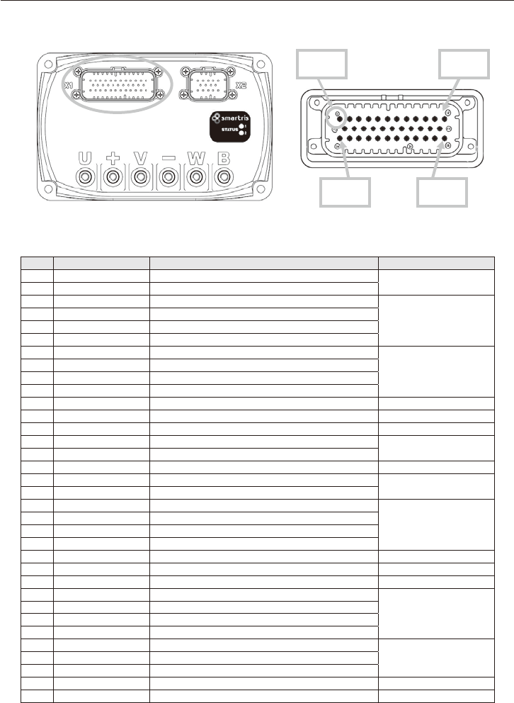
1-5 Installation and Terminal Connections
X2 – Motor feedback
X1 – Control wiring
LED status
48Vdc power input
Motor phases
Motor brake
Fig. 1-1 Eternal Appearance of the smartris Servo Drive Unit
Table 1-2 Power Connections
Pin No. Signal Description
+ +VBUS Connection to +VBUS (+48 Vdc)
-
-VBUS Connection to –VBUS
Table 1-3 Motor Connections
Pin No. Signal Description
U phase U Motor phase U
V phase V Motor phase V
W phase W Motor phase W
Note: See “3-1 Power Cables” regarding recommended cables.
Terminal:M6screw,7N• mtighteningtorque
Table 1-4 Bake Connections
Pin No. Signal Description
+ +VBUS “Brake+” and +VBUS connection
B BRAKE “Brake” and B connection
Note: Cable with 1 mm
2
-AWG19 or higher is recommended
8
1. Overview
■
X1 Connector Connections (Control Signals)
Note: See “11. Cables (Optional)” regarding cables.
Pin 1 Pin 12
Pin 24 Pin 35
Table 1-5 X1 Connector Control Signals
Pin No. Signal Description Electrical Characteristics
1 0V24 GND (control board power)
-
2 COMMON Digital input common
3 IN1 Digital input: Reserved
DC24V±20%
Input Impedance 3KΩ
4 IN2 Digital input: Reserved
5 IN3 Digital input: Emergency stop
6 IN4 Digital input: Reset
7 TX/485+ TX232 signal/485+signal
-
8 RX/485– RX232 signal/485–signal
9 485_T 120Ω terminal resistor 485 (connected to 485+)
10 GND_COM GND (RS232 Serial communication)
11 RET1 Safety relay1(output) Max. DC30V 0.5A (contact)
12 STO1 Safety relay STO1 (input) DC20~28V, 29mA (typ.)
13 GND_REF GND (analog command) -
14 REF– Analog input–
Input DC±10V or 0 to 10V
15 REF+ Analog input+
16 +10V 10Vdc output Output DC10V±4%
17 OUTDAC Analog output Output DC0 to 10V
Load Impedance 1kΩ or more
18 GND_DAC GND (analog output)
19 GND_CAN/GND_RS485 GND (CAN or Modbus communication)
Note:1
-
20 CAN_T/RS485_T 120Ω terminal resistor(connected to CAN_H or RS485+)
Note:1
21 NC -
22 COM_RET Common (RET1/RET2: output)
23 STO2 Safety relay STO2 (input) DC20~28V, 29mA (typ.)
24 24/48V Control board power (input) DC20~60V, 6W (typ.)
25 V_OUT Digital output common -
26 OUT1 Digital out1: Drive OK
DC24V±20%
27 OUT2 Digital out1: Drive warning
28 OUT3 Digital out1: Reserved
29 OUT4 Digital out1: Brake status (release/operation)
Note:2
30 CAN_L/RS485– Connected to CAN_L or RS485–
Note:1
-31 CAN_H/RS485+ Connected to CAN_H or RS485+
Note:1
32/33 NC -
34 RET2 Safety relay2 (output) Max. DC30V 0.5A (contact)
35 STO_COM Common (STO1/STO2: input) -
Notes: 1. CANopen or Modbus communication can be used this product.
Check the drive model that communication can be used. See 10-2 Nameplate and codes.
2. Valid if the brake is connected.

9
1. Overview
■
X2 Connector Connections (for Feedback)
Pin 1 Pin 5
Pin 10 Pin 14
Table 1-6 X2 Connector, Feedback Signals
Pin No. Resolver Absolute encoder
1 S2 (SIN+) SIN
6 S4 (SIN-) REFSIN
2 S1 (COS+) COS
7 S3 (COS-) REFCOS
3 R1 (REF+) DATA+
8 R2 (REF-) DATA-
10 - +8V
11 - GND
4 - -
9 - -
14 - -
5 SCH SCH
12 NTC1a NTC1a
13 NTC1b NTC1b
Note: See “10. Cables (Optional)” regarding cables.
DANGER
The following are precautions for avoiding injury and risk of death due to improper use.
■ Avoid ground loops in wiring for control devices.
- When connecting the PC, the encoder, switches, actuators, etc., to the control connector, never
connect ground (pins 1, 10, 13, 18, 19) and battery negative (–) terminals.
Never disconnect the battery negative (–) terminal while the battery positive (+) terminal is con-
nected to the drive unit. Excess current ows from the ground pin, so disconnecting a wire or
connector can result in damage or faults to controllers and peripherals.
- The controller connector grounds (pins 1, 10, 13, 18, 19) are connected to drive unit by internal
negative (–) terminals.
- Be sure to connect battery negative (–) terminals in controller ground wiring.
- Do not use power ground cables for connectors and switches.
- Shield external I/O signals to prevent eects from main power.

10
1. Overview
■
Connection Example
M: Motor
B: Brake
F: Feedback
Notes: 3.
Notes: 2.
Notes: 1.
Drive unit
Controller
: Sink connection
* : Source connection
Notes: 1. The potentiometer connections
2
.
Backup power supply for logic
3
.
CAN terminal connection: Pin 20 and Pin 31 (CAN H signal)
Fig. 1-2 Connection Example for Drive Unit and Controller

11
1. Overview
1-6 Ambient Conditions
This product must be installed in appropriate ambient conditions to ensure safe operation.
Faults due to modications or inappropriate storage conditions will void the product warranty.
Keep the device covered for protection from dust, metal lings, water, oil, etc.
Item Details
Ambient temperature
IEC60068-2-2
-10 °C - 40 °C
Ambient humidity ≤85% RH, no condensation
Altitude Altitude: 1000 m max.
Protection class IP54
Contamination level 2(EN 2, 61800, EN61800-5-1)
Storage Details
Storage temperature -10 °C - 70 °C
Storage humidity ≤90% RH, no condensation
1-7 Certication
(1) CE Compliance
This product is certied for the conformance with the following EC Directives by Certication Bodies.
- EMC Directive (2014/30/EU)
- RoHS Directive (2011/65/EU)
- WEEE Directive (2012/19/UE)
(2) Safety
This product is compliant with the following EN safety standards:
- EN 61800-5-1: Adjustable speed electrical power drive systems - Part 5-1: Safety requirements – Electri-
cal, thermal and energy.
(3) EMC Requirements
This product satises category requirements for emission and immunity conditions for “type-2 environ-
ments” (industrial environments).
- EN 61800-3: Adjustable speed electrical power drive systems - Part 3: EMC requirements and specic
test methods.

12
1. Overview
(4) Safety Conformity (STO)
This product is equipped with two-channel Safe Torque O (STO) input compliant with safety functions.
(Optional)
This function halts PWM output and safely stops torque of the drive unit.
The circuit designs have been tested and certied by TÜV SÜD.
The STO safety function for circuit designs in this product are compliant with the following EN standards:
- EN61508: Functional safety of electrical/electronic/programmable electronic safety-related systems
- EN61800-5-2 and category: Adjustable speed electrical power drive systems – Part 5-2: Safety require-
ments – Functional
- EN ISO 13849-1:2015: Safety of machinery — Safety-related parts of control systems — Part 1: General
principles for design.
Subsystems include safety conditions with the following characteristics:
EN 13849-1 EN 61508 PFHD [1/h]
PLe SIL3 -
(5) Ambient Conditions for Vibration and Shock
The drive unit satises the following specications:
•Vibration:DINEN60068-2-6:2008
•Vibrationfrequencyrange:10–150Hz
•Acceleration:5G
1-8 Motor and Circuit Protection
There is no need for connecting a thermal relay for motor protection. Overload protection is possible with
the I
2
t function (electronic thermal).
Protection function parameters are as follows:
•Nominalcurrent
•Peakcurrent
•Overload
Nominal current and peak current are motor characteristics. The overload time is the initial value due to
the load and motor, but can be set programmatically.
Drive behavior after the overload time has elapsed can be set as follows:
•Occurrenceofoverloadalarms
•Operationunderpeaknominalcurrent
The motor’s temperature sensor has a function for protecting the motor from overheating.
In that case, drive operation can be set as follows:
•Evenwiththesensordetectingtemperaturesabovethethreshold,continueoperationuntilthemotor
overheat alarm.
・ It is possible to read sensor temperature values and reduce the load or speed to lower the motor
temperature.
Drive Output Current
Model No. Nominal Current Peak Current (2sec)
AG110D4-A60## 11.5A 41.7A
AG110D4-1A5## 25.8A 96.3A
AG110D4-2A0## 35.8A 136.2A

13
1. Overview
1-9 Startup
EMC directives forbid startup before conrmation that this product was installed in compliance with EC
Directive standards.
Also, standards for machinery directives (2006/42/EC) and EMC directives (2014/30/EU) prohibit applica-
tion and operation of this product with incompatible mechanical systems.
Machine and system manufacturers must ensure EMC thresholds satisfying the requirements of EMC
standards.
(1) Proper Usage
This product can be applied to drive synchronous servo motors using permanent magnets
(servo motors compatible with machine and system feedback systems).
This product is certied for use in industrial applications. Note that its use in residential areas requires
additional EMC countermeasures.
The customer will need to prepare a risk analysis for the nal product.
CAUTION
-
Customers planning use for nonindustrial applications must rst obtain our approval.
(2) Inappropriate Uses
This product is incompatible with motors other than synchronous servo motors. It also cannot be used
in motors incompatible with feedback systems.
Note that installation in areas presenting the danger of ammable materials, ammable gases, dust,
etc., can result in re or explosion.
Do not install the drive unit or gearmotor of this product in such environments.
1-10 Location of Installation
Install this Protection Standard IP54 product in a place where it can operate reliably.
It must be installed in a location conforming to IP54 class or higher protective structures.
1-11
Maintenance
Perform periodic maintenance and inspections to ensure that the drive unit is free of abnormal appear-
ances, dust adhesion, and loose connectors or terminals.
Disassembling this product will void its warranty. When disassembling, safety functions corresponding
to standards are not guaranteed.

14
2. Dimensions
2-1 Dimensions
84.25
116
116
609
4-Ø6.4
72
Unit: mm Mass: 1.6kg
98.3
34.65 116.7
84.25 (with plug)
(34.65)
168.3
186
186
69
69

15
2. Dimensions
2-2 Installation
Safety Precautions
•Installthedriveunitinsideacontrolpaneltopreventhumidity,waterdroplets,andmetaldust.
•Beforeinstallation,conrmthatthedriveunitisnotdamaged.
•Ensuresucientventilationwithinthecontrolpanel.
•Donotoperatethedriveunitifcondensationgenerates.
2-3 Wiring Precautions
Safety Precautions
CAUTION
- Ensure that the system is displaying no alarms to conrm safety.
- Before operation, check that the wiring with the drive unit is correct and theses cables have no
damage.
Before operation, conrm there are no problems with the drive unit and wiring.
- Non-specication voltages, reversed polarity of connections, improper wiring, etc., can result in
drive unit faults or damage.
- Improper protection against excess power can result in damage to the drive unit or wiring.
- See “5. STO Safety Function (Optional).”
2-4 Power Adapters and Supplied Voltage
24V for STO logic and 48Vdc power supply must supply constant voltage.
CAUTION
- Using power adapters that do not conform to SELV/PELV designs can produce dangerously high
voltages that may result in injury or death.
48 Vdc power adapters must allow regeneration up to 60 Vdc during motor regeneration operation.
Power adapters must be designed to accommodate the above regeneration operation.

16
3. Technical Data
3-1 Power Cables
Thetablebelowshowsanexampleofcablesizeselectionforwiringtotheservomotorandpowersup-
ply.
Table 3-1 Example of Power Cable Selection
AGV load
(kg)
Motor output
(W)
Power source cable
(mm
2
) - AWG
Protective fuse
(A)
600 430 2.5 - AWG14 25
1000 600
4 - AWG12 50
1500 1000
1500 1000
6 - AWG10 100
2500 1500
Note: Power supply voltage is 48 Vdc (max. 60 Vdc)
Cables in the table are reference examples. Applicable to Lafert or similar servo motors.
■
This document is applicable to the following feedback.
・
Resolver
・
Absolute encoder

17
4. Operation Mode Functions
CAUTION
-
This product optionally includes a Safe Torque O (STO) safety feature.
Please conrm correct operation of circuits for this function before operation.
See “5. STO Safety Function (Optional)” for details.
4-1 Communication Mode
The open network CANopen or Modbus communication can be used this product.
Check the drive model that communication can be used. (See 10-2 Nameplate and codes)
See CANopen Communication Manual (No.DM1803E) or Modbus Communication Manual (No.
DM1804E).
The following chapter is written using CANopen communication as an example.
4-2 Motor Brake
Motor brake operates by being supplied power of the drive.
The DIG-OUT4 (digital output 4) signal operates the brake relay.
(The relay requires external power.)
The brake can be set to automatic or manual.
•Automaticmode: InputtingtheRUN/Enableoperationcommandallowsautomaticbrakerelease.
Brake power (+24 V)
•Manualmode: ThebrakereleasecommandcanbeissuedbyCANopencommunicationorapa-
rameter.
Brake -
Brake +
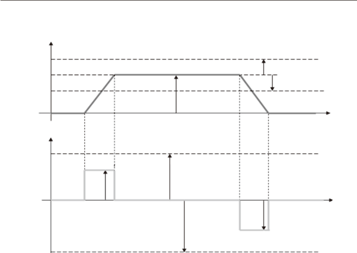
■
Automatic Mode
State
"Operation Enabled"
(RUN)
Brake delay Brake release time
Motor speed
Brake status
Output torque
Motor locked
Motor free
Set point = 0
(2) (3)
Fig. 4-1 Automatic Brake Operation

18
4. Operation Mode Functions
■
Manual Mode
In CANopen mode, set bit 1 of 60FEh (subindex 1).
•Setbrake[60FEh(subindex1),bit0]=1forbrakerelease.
(1) Standby to Operation Phase (STBY
→
RUN)
In STBY, the brake is released and the motor is locked.
During the time set by Delay 1, the motor is in the stop status even if the RUN signal is input.
Even after the Delay 1 time elapses and the brake is released, the motor remains stopped for the time
set by Delay 2.
After the Delay 2 time, RUN mode starts and the motor reaches the set speed.
Even when the motor is stopped, stall torque (retention torque) is generated.
Note: Brake delay time is the time from issuance of the brake release command to motor lock release.
Motor speed
Delay 1 Delay 2
Stop status
State
"Operation Enabled"
(RUN)
Brake
Brake Brake release
Set point = 0
Motor brake delay
3002h Sub-Index 2
Brake release time
3002h Sub-Index 3
Fig. 4-2 Automatic Brake Delay Time

19
4. Operation Mode Functions
(2) Phases from Operation to Standby (RUN
→
STBY)
In the RUN state, the brake is released. When halting, stop operation diers according to whether dy-
namic brake is enabled, as shown in the gure below.
Motor speed
Brake status
Output torque
State:
"Operation Enabled" (RUN)
State:
"Switched ON" (STBY)
Dynamic brake status
Brake timeout
3002hSub-Index 4
No dynamic brake
Dynamic brake Status = 1
Holding torque time
3007hSub-Index 2
With dynamic brake
Motor locked state
Decrement step ramp
3007hSub-Index 4
Stop delayDynamic Brake
Motor locked state
(4) (2)
Fig. 4-3 Dynamic Brake
The motor decelerates at the free run speed without dynamic brake.
Thebrakelocksthemotorwhenthespeedreacheszero,orwhenthedecelerationtimeexceedstheset
brake timeout time.
If there is the function of dynamic brake, deceleration occurs in the time set in the dynamic brake pa-
rameters.
After ramp deceleration completes, the brake's locking the motor, and the motor's stopping with the
delay time set in the dynamic brake parameters, the drive unit turns to be STBY mode.
20
4. Operation Mode Functions
4-3 Digital I/O
The following digital I/O are available.
・
Digital input 4: DIG-INx
・
Digital input 4: DIG-OUTx
・
Safety digital input 2: DIG- STO
(1) Digital Input
This is an analog mode for operating the motor by using two digital inputs.
・
DIG-IN1 : reserved
・
DIG-IN2 : reserved
DIG-IN3 can be programmed as “Enable Input Emergency.”
In this case, DIG-IN3 is used for transition from RUN to STANDBY in an emergency with dynamic brake.
This function is enabled through the following settings:
•CANopen:Setobject0x3008h(EmergencyInputEnable)subindex1.
Logic for dynamic brake input (DIG-IN3) can be selected.
•CANopen:Setobject0x3008h(EmergencyInputEnable)subindex2.
DIG-IN4 resets the drive unit hardware.
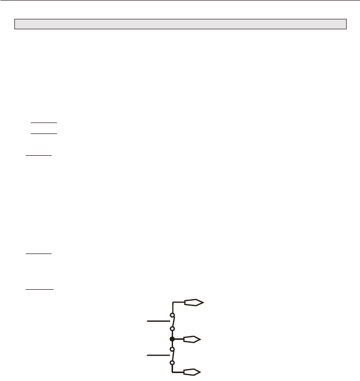
(2) Digital Input, Safety STO
DIG-STO : STO input is shown in the following circuits.
Fig. 4-4 STO Output Feedback Relay
If the application requires deceleration and stop (controlled deceleration and stop) before use of the
STO function, rst perform deceleration and stop operation, then activate the STO function after stop.
1. Drive deceleration and stop operation
2. In the case of stop state, disable the drive unit.
3. If there is a suspended load, mechanically lock the drive as well.
4. Activate the STO function.

21
4. Operation Mode Functions
CAUTION
The drive unit cannot generate torque when the STO function operates, so load cannot be main-
tained.
-
When the STO function is operated during driving, the drive unit stops without control.
-
If the drive unit has an STO function, it is necessary to conrm that all circuits for the drive unit
are correct in addition to function settings for it.
■
STO 2 Input Feedback
Feedback signals for each STO input can be monitored by two-channel relay output (RET1, RET2).
The status of STO commands can be monitored by output from each relay. (Safety functions can be
completely monitored.)
The state of digital input can be read with CANopen DSP402 (60FDh: Sub-Index 0)
(3) Digital Output
DIG-OUT1: Indicates the drive state.
•1=DriveOK
•0=Drivefault
DIG-OUT2 : Indicates the drive warning.
•1=Thereisawarningactivate.
•0=Nowaring.
DIG-OUT3 : Reserved.
DIG-OUT4 : Indicates the brake status.
•1=Brakerelease,motorshaftfree.
•0=Brakeoperation,motorlock
CANopen DSP402: 0x60FE can can be read with the status of digital output.

22
4. Operation Mode Functions
4-4 Torque Limit (Add from FW Ver.2.0.1)
NOTE
It is possible to set a torque limit to set the congured maximum torque in the motor. The value shall be
given percent of rated current.
Setting value for peak current (0x3003:2) is depend on the drive model.
Model No. Peak Current
AG110D4-A60## 41.7A
AG110D4-1A5## 96.3A
AG110D4-2A0## 136.2A
while in CANopen there are dierent values of maximum torque:
・Positive takes eect in the case of motive operation is positive velocity or regenerative operation is
negative velocity.
・Negative torque takes eect in the case of motive operation is negative velocity or regenerative op-
eration is positive velocity
The default value of torque limit is 100% and modies can't be saved in EEPROM memory but it can be
saved in RAM.
WARNING
・ This object is controlled by some limits of drive. If the value is not correct the drive sends an
AbortCode.Ifthevalueisnotcorrectduringinitializationthedrivesendsanerrormessageswith
Emergency Protocol. See Error Code 0x8B23. The range is [1 to 100] %.
・ The setting value of torque limit returns to 100% (default value) when the power is turned o. It
is not saved in EEPROM.
4-5 Overload Management (I
2
T) (Add from FW Ver.2.0.1)
NOTE
The smartris drive uses the I
2
t protection method to prevent motor winding and insulation damage
caused by high motor temperature due to motor excessive work.
The I
2
t algorithm evaluates the motor dissipating heat without any sensor. When the evaluated tem-
perature exceeds the maximum, I
2
t algorithm protects the motor placing the drive in Fault Overload
The I
2
t principal algorithm calculation is as follows:
I
2
T=(I
p
2
– I
n
2
) * T
p
Output Current [A]
Time [s]
I
p
I
n
T
p
I
p
: Motor peak current (rms)
I
n
:Motor nominal current (rms)
T
p
: Motor peak current time in seconds
Fig.4-5 Overload Management I2T
Note: FW ver. is listed in the nameplate. See 10-2 Nameplate and codes.

23
4. Operation Mode Functions
The smartris drive manage also 2 kind of Overload:
・
Overload at low speed (default 30 rpm - settable only by manufacturer)
・
Protection to Overload close events
4.5.1 Overload at low speed
In smartris drive there is a function to modify the Overload function depending by speed.
Under a specic value the Energy is reduced. This means that at low speed the I
2
t time is reducing to half
and the Rated Current is around 70% of the standard.
At normal speed there is no eect.
It is possible with CANopen DSP402 read the status with the bit 11 of statusword (0x6041 object).
During the limitation there is emergency message that describes when the drive is in Warning Limita-
tion i
2
t for Overload (error code 0x2351) and in alarm (error code 0x2350).
4.5.2 Overload with closer events
There is a function that prevent the drive goes to Run if numerous close I
2
t events have occurred.
After 2 consecutive Fault Overload Events it is necessary to wait one minute before enabling the drive,
otherwise the drive will go into Fault I
2
t Overload Protection (LED status code 5,2).
When re-enabling the drive, reset after unlocking the interlock.
It is possible with CANopen DSP402 read the alarm (error code 0x2352).

24
5. STO Safety Function (Optional)
Safety circuits include safety functions based on IEC 61800-5-2.
The STO module conforms to uncontrolled stop in “Stop category 0: IEC 60204-1,” shutting o torque
output.
5-1 STO (Safe Torque O)
In the STO state, power for the motor to generate torque is not supplied.
The motor therefore cannot rotate.
Notes: 1. This safety function is compatible with uncontrolled stop.
2. Use this function when required to shut o output to prevent unexpected start-up.
3. In the presence of external inuences (falling due to suspended load, etc.), it is necessary to
use an additional measures (a mechanical brake, etc.) to prevent danger.
(1) STO Connections
Pin 11–12
Pin 22–23
Pin 34–35
Table 5-1 I/O signals (AGV)
Pin No. Signal Description
11 RET1 Safety relay 1 (output)
12 STO1 Safety relay STO1 (input)
22 COM_RET Common (RET1/RET2: output)
23 STO2 Safety relay STO2 (input)
34 RET2 Safety relay 2 (output)
35 STO_COM Common (STO1/STO2: input)
5-2 Hardware Specications
•STOinput:STO1,STO2(common:STO_COM)
•Relayoutput:RET1,RET2(common:COM_RET)
Table 5-2 STO Input Specications
STO Input Data
STO Inactive status (normal operation) input voltage 20 - 28 Vdc
STO Active (SAFETY) input voltage < 2.4 Vdc
Input current 29 mA
Active response time (time from normal to STO operation) 10 ms
RET1, RET2 connection specications (Max. voltage/current for contact) 30 V/0.5 A

25
5. STO Safety Function (Optional)
Table 5-3 I/O Relay Operation
Input 1 Input 2 Output 1 Output 2 Output Status
STO1 STO2 RET1 RET2 Status
0 V
0 V
Closed
Closed
Safety24V Open
0V
24V
Closed
Open
24V Open Normal mode
■
IfeitherSTO1orSTO2is0V,safetymode(zerotorque)operates.
Fig. 5-1 STO Output Feedback Relay
5-3 Software Specications
Safety procedure: RUN
→
STANDBY
→
SAFETY
Recovering from SAFETY to STANDBY mode requires setting STO and RUN to reactive.
The recovery procedure is as follows.
•InCANopenmode: SAFETY
→
SWITCH ON DISABLED
→
READY TO SWITCH ON
→
SWITCH ON
→
OPERATION ENABLED
SAFETYRUN
STANDBY
(Run not active)
(RUN active)
(STO not active) and
(RUN not active)
STO active
Fig. 5-2 STO State Machine

26
5. STO Safety Function (Optional)
5-4 Safe Operation Sequence Procedure
If deceleration and stop (controlled deceleration and stopping) is required before using the STO func-
tion, rst perform deceleration and stop operation, then operate the STO function.
1. Drive deceleration and stop operation.
2. In the case of stop state, disable the drive unit.
3. If there is a suspended load, mechanically lock the drive as well.
4. Activate the STO function.
CAUTION
The drive unit cannot generate torque when the STO function operates, so load cannot be main-
tained.
-
When the STO function is operated during driving, the drive unit stops without control.
5-5 Example of Schematic Application
Drive unit
Safety controller
Fig. 5-3 STO Application Example
■
STO 2 Input Feedback
Feedback signals for each STO input can be monitored by two-channel relay output (RET1, RET2).
The status of STO commands can be monitored by output from each relay. (Safety functions can be
completely monitored.)
The state of digital input can be read with CANopen DSP402 (60FDh: Sub-Index 0)
5-6 Function Check
The STO function should be conrmed on rst startup after system wiring or parts replacement.
Please conrm that STO circuits are functioning correctly every six months.
27
6. CANopen Communication
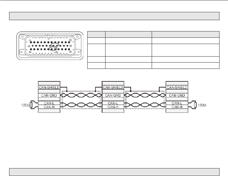
6-1 CANopen Network Topology
Table 6-1 CANopen Signals
Pin No. Signal Description
19 GND_CAN/GND_RS485 GND (CANopen or RS485 Modbus)
20 CAN_T/RS485_T
Termination resistor 120Ω
(Connection for CAN_H/RS485+)
30 CAN_L/RS485- Connection for CAN_L or RS485-
31 CAN_H/RS485+ Connection for CAN_H or RS485+
Connector X1
Fig. 6-1 CANopen Wiring
The two ends of the CAN cables have to be terminated by a resistor of 120Ω.
The CAN bus can be closed with a resistance terminator into to the drive using Pin 20. The CAN_T pin
has to connect to CAN_H pin on Connector X1.
6-2 CANopen Bitrate and Node ID
Compliance with CiA DS301 v4.02 and DSP402 v2.0 directives.
•CANopenbaudrate:50K,125K,250K,500K,800K,1000K(initialsetting:1000Kb)
•NodeID(initialsetting:1)
28
6. CANopen Communication
6-3 CANopen Overview
Features
•TPDO7,RPDO7, event timer, access unit 8 bits
•Heartbeat,nodeguarding
•Baudratesetting:50K,125K,250K,500K,800K,1000K(initialsetting:500K)
•Enableinput(standbymodeatL-levelinput,switchONdisabled).
•NodeIDsetting(default:ID1)
•Parametersarestoredinnonvolatilememory(communication+manufacturername+deviceprole)
•LoadinitialCANopenparametervaluefrom ROM by command.
Compliance with CiA DS301 v4.02 and DSP402 v2.0 directives.
See “CiA DS301 Standards” for additional information.
■
Reference Materials
• CANopen Manual (No.DM1803E)
- CiA 301 (310_1v01010005_cor.pdf)
- CiA 402 (CiA® 402 Draft Standard Proposal.pdf)
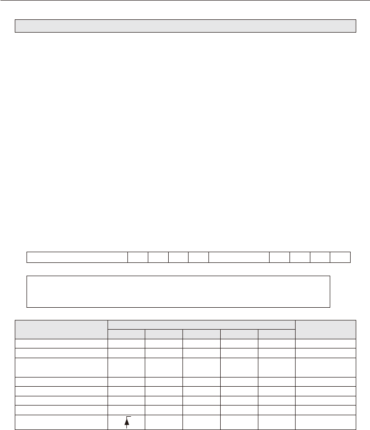
(1) Object 6040h: Controlword
This object is used in CiA-402 FSA and CiA-402 modes and for control of manufacturer-specic entities.
Controlword comprise the following bits.
15 11 10 9 8 7 6 5 4 3 2 1 0
ms r oms h fr oms eo qs ev so
MSB LSB
ms: manufacturer-specic h: halt qs: quick-stop
r: reserved fr: fault reset ev: enable voltage
oms: operation mode specic eo: enable operation so: switch ON
Command
Controlword Bits
Transition
Bit 7 Bit 3 Bit 2 Bit 1 Bit 0
Shutdown 0 X 1 1 0 2, 6, 8
Switch ON 0 0 1 1 1 3
Switch ON + operation
enabled
0 1 1 1 1 3 + 4 Note)
Voltage disabled 0 X X 0 X 7, 9, 10, 12
Quick stop 0 X 0 1 X 7, 10, 11
Operation disabled 0 0 1 1 1 5
Operation enabled 0 1 1 1 1 4, 16
Fault reset
X X X X 15
Note: After performing switch ON, operation automatically transfers to enabled. This transition interval re-
quires 20 ms or more.
・
Bits 9, 6, 5, 4: Operation mode specic
・
Bit 8 (halt function): This is an operation mode specic function.
At bit 1 commands are interrupted and drive unit execution halts at the dened option code. After
canceling the stop function, the command operation continues.
・
Bit 10 (reserved): Please set to 0.
・
Bit 11 (manufacturer-specic, warning recognition): Setting to 1 clears the statusword warning bit.
・
Bits 12, 13, 14, 15 (manufacturer-specic): Not used

29
6. CANopen Communication
(2) Object 6041h: Statusword
This object indicates the current FSA status. There are operation mode and manufacturer-specic bits.
15 14 13 12 11 10 9 8 7 6 5 4 3 2 1 0
ms oms ita tr rm ms w sod qs ve f oe so rtso
MSB LSB
Bit Description M/O
0 Ready to switch ON
M
1 Switched ON
2 Operation enabled
3 Fault
4 Voltage enabled
5 Quick stop
6 Switch ON disabled
7 Warning
O
8 Manufacturer-specic
9 Remote
M10 Target reached
11 Internal limit operation
12 - 13 Operation mode specic
O
14 - 15 Manufacturer-specic
・
Bit 4 (voltage enabled): 1 indicates that high voltage is supplied to the drive unit.
・
Bit 5 (quick stop): 0 indicates on a quick stop request.
・
Bit 7 (warning): 1 indicates that a warning status occurs.
Note that warnings are not errors or faults (ex: temperature increase, job halt, etc.) The drive unit FSA
status therefore does not change.
Warning denitions can be read from the warning parameter object (2003h).
・
Bit 10 (target reached): 1 indicates that the target reached its set value.
The set value is operation mode specic, and dened in clauses corresponding to some of the prole
specications.
Bit 10 is set to 1 when the operation mode changes.
This bit changes on software updates of target value.
・
Bit 11 (internal limit active): 1 indicates that the internal limit functions.
・
Bits 12, 13: Operation mode specic (depends on prole set).
・
Bit 14 (manufacturer specic: safety): 1 indicates that the drive unit is in safety mode.
・
Bit 15 (manufacturer specic: fault): 1 indicates that the drive unit faults.

30
6. CANopen Communication
(3) Object 6060h: Mode of Operation
This object can be used to set operation modes and
shows value for required operation modes. Actual operation modes are reected in the Modes_of_op-
eration_display object.
Bit denitions are as follows.
Bit Description Access
0 No mode change/No mode assignment
rw
1 Prole position mode (Coming soon)
2 Reserved
3 Prole velocity mode
4 Torque prole mode
5 to 10 Reserved
-1 Manufacturer specications
Usable operation modes
•Mode3:Prolevelocitymode
•Mode4:Proletorquemode
Note: When setting measurement unit conversion, see chapter 8.
(4) Object 6061h: Mode of Operation Display
This object denes the actual operation mode.
Object description
Index Object Code Data Type Category
6061h VAR Integer 8 Mandatory
Entry description
Subindex Access PDO Mapping Value Range Default Value Unit
00h ro YES (default) -128 - 10 - -
Bit denitions are as follows.
Bit Description Access
0 No mode change/No mode assignment
ro
1 Prole position mode (Coming soon)
2 Reserved
3 Prole velocity mode
4 Prole torque mode
5 to 10 Reserved
-1 Manufacturer specications

31
6. CANopen Communication
■
Control Composition in Prole Velocity Mode
Velocity window (606Dh)
Velocity window time (606Eh)
Speed controller
Target reached
(Statusword bit 10 6041h)
EC
Encoder
Motor
M
PWM
amps
Velocity demand
value
(606Bh)
Target
velocity
(60FFh)
Ramp
generator
Velocity actual value
(606Ch)
+
–
PID
Velocity/position
calculation
I
2
t current limit
Velocity threshold (606Fh)
Velocity threshold time (6070h)
Set point acknowledge
(Statusword bit 12 6041h)
Current
Velocity
Fig. 6-2 Control Composition in Prole Velocity Mode

32
6. CANopen Communication
Target velocity
Maximum prole
Comparator
Velocity unit
multiplier
velocity unit
multiplier
Multiplier
Motor
EC
Encoder
Velocity reached
window
Velocity unit
multiplier
Limit value
Velocity actual value (606Ch)
Velocity window (606Dh)
Acceleration
limit function
velocity limit
function
Maximum motor speed
Polarity (607Eh)
Acceleration prole
Prole
Target reached
Statusword (6041h)
Velocity limit
function output
Motion prole
Maximum acceleration
Maximum deceleration
Quick stop deceleration
Velocity window
time (606Eh)
Speed
control
loop
(606Bh)
Target limit
Fig. 6-3 Speed Control Composition
■
Prole Velocity Mode (3)
In prole velocity mode, prole movement is dened according to velocity and acceleration/decelera-
tion commands.
Start velocity control prole:
(1) Writingobject6060h=Byinputting3,thedriveunitmovestotheoperationmodeofproleveloc-
ity mode.
(2) Operation enabled
(3) Set acceleration and deceleration in objects 6083/6084h, respectively.
(4) Operation starts when the target velocity is set in Object 60FFh.
To start operation, clear bit 8 in object 6040h.
The target velocity can be changed during operation. Operation stops when any of the following condi-
tions are satised:
・
Thetargetvelocityissettozero.
・
The Halt command is issued.
・
An error occurs.
33
6. CANopen Communication
■
Prole Velocity Characteristics
Speed
Acceleration
Prole velocity
(60FFh)
Maximum acceleration
(60C5h)
Maximum deceleration (60C6h)
Prole deceleration
(6084h)
Prole acceleration
(6083h)
Velocity window (606Dh)
Velocity window (606Dh)
Fig. 6-4 Prole Velocity Characteristics

34
6. CANopen Communication
■
Run Sequence
(1) Power switch ON
(2) Verify LED status 1, 2 initial state (INIT mode)
(3) Congure prole velocity: 0x6060
→
0x03
(4) Ready to switch ON setting: Controlword write 0x6040
→
0x06
(5) Switched ON setting: Controlword write 0x6040
→
0x07
(6) Verify whether smartris drive state is switched ON: Statusword read 0x6041
→
0x23
(7) Operation enabled setting: Controlword write 0x6040
→
0x0F
(8) Verify whether LED status is enabled
Verify whether smartris drive state is enabled: Statusword read 0x6041
→
0x27
Verify brake release.
(9) Read speed command set value 0x60FF
→
0x03e8 (Ex: set 1000 r/min)
(10) If motor revolutions are conrmed, verify motor speed (after acceleration is complete):
Read 0x606C
→
0x03e8 (Ex: 1000 r/min)
Note: The motor immediately stops upon issuance of the STO safety command (
SAFETY ).
Commands being executed are immediately halted upon issuance of a stop command (
STOP ).
Commands being executed are immediately halted when a fault (
FAULT ; see 8. Diagnostic Table
8-2) occurs.
35
6. CANopen Communication
SAFETY
Safety
3) Congure prole velocity
4) Ready to Switch ON
5) Switched ON
7) Operation enable (ENABLE)
Quick stop active
Fault
Fault detection
1
2
3
4
5
T8
INIT
FAULT
STOP
RUN
STANDBY
6) Verify switched ON
9) Set point speed
8) Verify enable
10) Verify motor running
and speed
2) Verify LED status INIT
1) Switch ON power supply
Fig. 6-5 CANopen Run Sequence

36
6. CANopen Communication
6-4 Torque Prole (Add from FW Ver.2.0.1)
NOTE
In the prole Torque operating mode, the motor executes a movement according to a target torque or
current sent by the master controller. The current regulator (torque control) is specied a current pro-
portional to the target torque. Note: FW ver. is listed in the nameplate. See 10-2 Nameplate and codes.
Position Actual Value (6064h)
Position
Trajectory
generator
Target Torque (6071h)
Target Demand (6074h)
Torque
Control
and
Power
Stage
Motor
Torque slope (6087h)
Torque Prole Type (6088h)
Max Torque (6072h)
Torque Actual Value (6077h)
Velocity Actual Value (606Ch)
Enc
Velocity
Max Current (6073h)
Max Rated Torque (6076h)
Max Rated Current (6075h)
Torque Limit (60E0h) (60E1h)
■
Object Entries
The following objects are available for the control prole velocity and the behavior of the drive.
Index Object Name Type M/O Attr. Description
6071h VAR Target torque INT16 M rw
This object shall indicate the congured input value for the torque controller in
prole torque mode. The value shall be given per thousand of rated torque.
6087h VAR Torque slope U32 M ro
This object shall indicate the congured rate of change of torque. The value shall
be given in units of per thousand of rated torque per second.
6088h VAR
Torque prole
type
INT16 O rw
This object shall indicate the congured type of prole used to perform a torque
change.
6073h VAR Max current U16 O rw
This object shall indicate the congured maximum permissible torque creating
current in the motor.
6075h VAR
Motor rated
current
U32 O rw
This object shall indicate the congured motor rated current. It is taken from the
motor's nameplate. Depending on the motor and drive technology, this current is
DC, peak or current (rms). All relative current data refers to this value. The value
shall be given in mA.
6077h VAR
Torque actual
value
I16 O ro
This object shall provide the actual value of the torque. It shall correspond to the
instantaneous torque in the motor. The value shall be given per thousand of mo-
tor nominal current.
6078h VAR
Current actual
value
I16 O ro
This object shall provide the actual value of the current. It shall correspond to the
current in the motor. The value shall be given per thousand of motor nominal
current. This value is ltered.
6079h VAR
DC link circuit
voltage
U32 O ro
This object shall provide the instantaneous DC link current voltage at the drive
device. The value shall be given in mV.
6074h VAR
Torque
demand
I16 O ro
This object shall provide the output value of the trajectory generator. The value
shall be given per thousand of rated torque.
60E0h VAR
Positive torque
limit value
U16 O rw
This object shall indicate the congured maximum positive torque in the motor.
The value shall be given percent of rated current. Positive torque takes effect
in the case of motive operation is positive velocity or regenerative operation is
negative velocity.
60E1h VAR
Negative
torque limit
value
U16 O rw
This object shall indicate the congured maximum negative torque in the motor.
The value shall be given percent of rated current. Positive torque takes effect
in the case of motive operation is positive velocity or regenerative operation is
negative velocity.
Note: Torque prole characteristic depends on the setting of torque prole type (6088h).

37
6. CANopen Communication
Torque Prole Type”(6088h):“0”: Linear Ramp
Torque Prole Type”(6088h):“-1”: Immediately
Actual Torque
Target Torque (6071h)
Actual Torque
1sec
Torque Slope (6087h)
Target Torque (6071h)
1sec
Torque Slope (6087h) Invalid
■
Torque Prole Operation Mode
In the Prole Torque operation mode, a movement is made with a specied target torque.
To initiate a torque-controlled movement:
・
Switch the operation mode to Prole Torque mode by writing 4 to object 6060h.
・
Enable operation.
・
Start motion by setting the target torque in object 6071h.
Target torque can be changed on-the-y during motion. The Torque slope can be changed in run time,
the other objects must be saved in EEPROM.
If changed, reset is required. (Do not change the other objects during the drive operation.)
The motion ends when one of the following conditions is met:
・
Target torque is set to 0.
・
Stop caused by Halt or Quick Stop
・
Stop caused by an error

38
6. CANopen Communication
6-4 DSP402 State Machine
For additional information, see denitions in “DSP402 v2.0.”
Start
Fault
Fault reaction active
Operation enable
Not ready to
switch ON
Ready to
switch ON
Switch ON
disabled
Switched ON
Quick stop active
Power
enabled
Power disabled
Fault
Fig. 6-6 DSP402 State Machine
The actual status can be read from the statusword. (standard code: dened in CiA DSP402).
State N° Description
Not ready to switch ON S0
Performingself-testduringdriveunitinitialization.
Brake output status. Drive unit function is
disabled.
An internal state, where communication is possible only at the end of this
state.
Users cannot acquire or monitor this state.
Switch ON disabled S1
Driveunitinitializationcompleted.Driveunitparametersetupiscom-
pleted.
Drive unit parameters are modiable. Drive unit function is disabled.
Note: Errors are not displayed in this state.
Application-side state transition processing is required.

39
6. CANopen Communication
State N° Description
Ready to switch ON S2
Drive unit parameters are modiable.
Drive unit function is disabled.
Switched ON S3
Power amp is standby.
Drive unit parameters are modiable. Drive unit function is disabled.
Operation enabled S4
No faults are detected. Drive unit functions are enabled and power is sup-
plied to the motor.
Drive unit parameters are modiable.
The brake is automatically released at the timing set by brake parameters.
Quick stop active S7
Drive unit parameters are modiable. Activating the quick-stop function.
Drive unit functions are enabled and power is supplied to the motor.
The motor is stopped or is stopping by the quick stop active.
Motor deceleration is completed and the drive unit is stopping.
If the quick stop active code (object 0X605A) is 0, the state of the drive is
switch ON disabled.
Fault reaction active SE
Drive unit parameters is modiable. Drive unit fault occurred.
Performing fault reaction. Drive unit function is disabled.
Users cannot acquire this status. This status automatically transfers to the
fault status.
Fault SF
Drive unit parameters are modiable.
Drive unit fault occurred. Drive unit function is disabled.

40
6. CANopen Communication
6-5 Speed Polarity
Speed set value can be inverted by a CANopen mode (either clockwise or counterclockwise).
This object aects the signs on “Position_demand_value” and “Velocity_demand_value.”
Object description
Index EDS Name Object Code Data Type Category
607Eh Polarity VAR Unsigned 8 Mandatory
Entry description
Subindex Description Access PDO Mapping Value Range Default Value
0 Polarity rw None 0 - 192 00h
Bit
7 6 5 4 3 2 1 0
Positional
polarity
Speed
polarity
Reserved region (0)
MSB LSB
The following value denitions are valid:
•Bitvalue=0:+1timestherequiredvalue
•Bitvalue=1:-1timestherequiredvalue
6-6 Store and Restore
The CiA CANopen protocol specications dene objects that store and restore parameters.
•Object1010h:Storeparameter
•Object1011h:Restoreparameter
In order to save all parameters, the master writes in the SDO 1010h index the value “save” to one of the
subentries of the object.
By this processing, corresponding parameter is written in nonvolatile memory.
Parameters are automatically loaded into the object dictionary after an NMT reset node or NMT reset
communication.
The following objects are modified by writing to object 1010h:2h (communication parameters) and
saved in EEPROM:
•1000h:Devicetype
•1001h:Errorregister
•1002h:Manufacturer-specicstatusregister
•1003h:Predenederroreld(historylist)
•1005h:COB-IDSync
•100Ch:Guardtime
•100Dh:Lifetimefactor
•1014h:COB-IDEMCY
•1017h:Producerheartbeattime
•1018h:IdentityObject

41
6. CANopen Communication
•1029h:Errorbehavior
•1400h:RxPD01parameter
•1401h:RxPD02parameter
•1402h:RxPD03parameter
•1403h:RxPD04parameter
•1600h:RxPD01mapping
•1601h:RxPD02mapping
•1602h:RxPD03mapping
•1603h:RxPD04mapping
•1800h:TxPD01parameter
•1801h:TxPD02parameter
•1802h:TxPD03parameter
•1803h:TxPD04parameter
•1A00h:TxPD01mapping
•1A01h:TxPD02mapping
•1A02h:TxPD03mapping
•1A03h:TxPD04mapping
The following objects are modied by writing to object 1010h:3h (application parameters) and saved in
EEPROM:
•6073h:Peakcurrent
•607Eh:PolarityNote
•607Fh:Maximumprolevelocity
•6080h:Maximummotorspeed
•6083h:AccelerationproleNote
•6084h:DecelerationproleNote
•6096H:Velocityfactor
•6097h:Accelerationfactor
•60C5h:Maximumacceleration
•60C6h:Maximumdeceleration
The following objects are modied by writing to object 1010h:4h (manufacturer settings parameters)
and saved in EEPROM:
•2000h:IDNode
•2001h:Baudrate
•3002h:BrakeparametersNote
•3007h::DynamicBrakeparametersNote
•3200h:PIDcurrentNote
•3201h:PIDvelocityNote
•3202h:PIDpositionerNote
•3203h:PIDdecouplingNote
Note: Parameters modiable in real time that will be lost if the drive unit is shut o.
All parameters can be stored in EEPROM. Modication requests are not accepted until a power reset or

42
6. CANopen Communication
until the CANopen “RESET COMM (NMT)” message is sent to the drive unit.
Manufacturer setting parameters are stored in a protected EEPROM called “Golden Image.”
You can use the restore parameter 0x1011 to return EEPROM parameters to factory parameters.
In order to avoid the restoring of default parameters by mistake, the master sends the SDO 1011h and
writes the signature "load" to one of sub-index.
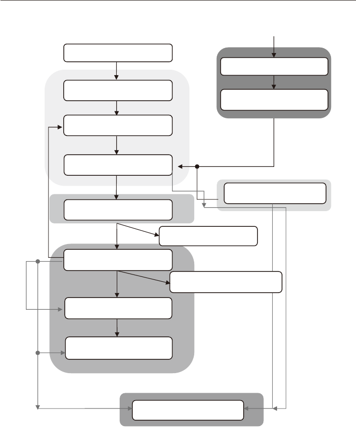
■
Function Mode for Restoring Factory Parameters:
Restore default (Index 1011)
Power ON/NMT reset
Boot up message
Parameters store (Index 1010)
Factory parameters
active
If actual settings are not stored, fac-
tory parameters will be reloaded and
enabled before the next reset.
Factory settings stored

43
7. Modbus Communication
7-1 Connection for Modbus Communication
Table 7-1 Modbus Signals
Pin No. Signal Description
19 GND_CAN/GND_RS485 GND (CANopen or RS485 Modbus)
20 CAN_T/RS485_T
Termination resistor 120Ω
(Connection for CAN_H/RS485+)
30 CAN_L/RS485- Connection for CAN_L or RS485-
31 CAN_H/RS485+ Connection for CAN_H or RS485+
Connector X1
GND_COM
RS485
−
RS485+
GND_COM
RS485
−
RS485+
GND_COM
RS485
−
RS485+
120 120
Fig. 7-1 Connection for Modbus Communication
The two ends of the CAN cables must be terminated by a resistor of 120Ω.
The CAN bus can be closed with a resistance terminator into to the drive using Pin 20. The CAN_T pin
has to connect to CAN_H pin on Connector X1.
7-2 Modbus Communication Settings
Write Single Holding Resistor (0x06) / Read Holding Resistors (0x03)
Physical Address
Variable PDU Address (W/R) Default Value Choice
Modbus Address 0x0028 1 1 ~ 247
Baud Rate
Variable PDU Address (W/R) Default Value Choice
Modbus Baud Rate 0x0035 192
→
19200
96
→
9600 b
192
→
19200 b
384
→
38400 b
576
→
57600 b
1152
→
115200 b
Communication Settings
Variable PDU Address (W/R) Default Value Choice
Parity
Stop Bits
Data Bits
0x002B 0
0
→
NO parity/ 2 Stop Bits/ 8 Data Bits
1
→
ODD Parity/1 Stop bit/ 8 Data bits
2
→
EVEN Parity/1 Stop Bit/8 Data Bits
WARNING
・
The Modbus Address is the physical address and depends if there are more devices together.
・
The modies of Baud rate or Parity can cause communication issues.
・
They depend to Hardware connection.
・
The smartris drive is always set as a slave.

44
7. Modbus Communication
7-3 List of Read Input Registers
Read from Drive (0x04)
Default Value Unit
HEX DEC Name
0x0042 66 Speed setpoint 0 RPM
0x0047 71 Current torque setpoint 0 Arms/100
0x005E 94 Digital inputs
- -
0X005F 95 Digital outputs
0x0060 96 Drive status
0x0061 97 Warning code Low
0x0062 98 Warning code High
0x0063 99 Error code
0x0064 100 Bus DC Link - V/100
0x0065 101 Motor temperature
- ℃ /100x0066 102 Heat-sink temperature
0x0067 103 Board temperature
0x0068 104 Motor speed 0 RPM
0x0069 105 Torque current 0
A/100
0x006A 106 I
2
T Energy value 0 %
0x006B 107 Axis position Low
0
Pulse0x006C 108 Axis position High
0X006D 109 Feedback pulse -
0x006E 110 Filtered velocity 0 RPM
7-4 List of Read Holding Registers
Read Only (0x03)
Default Value Unit
HEX DEC Name
0x0001 1 Controlword - -
0x0003 3 Full scale velocity L=3000, M=4500, S=4500 RPM
0x0028 40 Modbus address 1
-
0x002B 43 Communication settings 0
0x0035 53 Modbus baud rate 192
0x0036 54 Communication loss time 0
0x003C 60 PID velocity KP L=300, M=200, S=70
i.u.0x003D 61 PID velocity KI L=700, M=400, S=300
0x003E 62 PID velocity KV L=1000, M=600, S=500
0x003F 63 Speed ramp state 1: Ramp enable -
0x0040 64 Speed ramp up time
2000 ms
0x0041 65 Speed ramp down time
0x0043 67 Speed/Torque polarity 0 -
0x0044 68 Limit torque positive
100 %
0x0045 69 Limit torque negative
0x0046 70 Slope ramp (Torque) 0 (Motor rated current/1000)/s
0x004E 78 Brake managed 1: Blake enable
-
0x004F 79 Brake mode 1: Manual brake enable
0x0050 80 Brake type Depend on brake type
-
0x0051 81 Dynamic brake enable 1: Dynamic brake enable
0x01FF 511 FW release customer Depend on FW release
0x0201 513 HW release Depend on HW release
0x0202 514 Parameter release
Depend on parameter
release
0x0203 515 Motor type Depend on motor
0x0204 516 STO check
Depend on drive
0x0205 517 Feedback
0x0207 519 Operation mode -

45
7. Modbus Communication
7-5 List of Write Single Holding Registers
Write Parameters (0x06)
Default Value Unit
HEX DEC Name
0x0000 0 Store EEPROM -
-
0x0001 1 Controlword 0
0x0028 40 Modbus address 1
0x002B 43 Communication settings 0
0x0035 53 Modbus baud rate 192
0x0036 54 Communication loss time 0 ms
0x003C 60 PID velocity KP L=300,M=200,S=70
i.u.0x003D 61 PID velocity KI L=700,M=400,S=300
0x003E 62 PID velocity KV L=1000,M=600,S=500
0x003F 63 Ramp enable 1: Ramp enable -
0x0040 64 Speed ramp up time
2000 ms
0x0041 65 Speed ramp down time
0x0042 66 Speed setpoint 0 RPM
0x0043 67 Speed/Torque polarity 0 -
0x0044 68 Limit torque positive
100 %
0x0045 69 Limit torque negative
0x0046 70 Slope ramp (Torque) 1000 (Motor rated current/1000)/s
0x0047 71 Current torque setpoint 0 Arms/100
0x004E 78 Brake managed 1: Blake enable
-
0x004F 79 Brake mode 1: Manual brake enable
0x0051 81 Dynamic brake enable 1: Dynamic brake enable
0X0207 519 Operation Mode
-0x5A5A 23130 Restore manufacturer data
0xA5A5 42405 Reset Drive

46
7. Modbus Communication
START
NOT READY TO SWITCH ON
FAULT
FAULT REACTION ACTIVE
T0
T1
T2
T3
T
5
T4
T10
T9
T7
T8
STAND BY
Fault
STOP
RUN
Power Disabled
Power Enabled
Safety
Safety
T6
T5
EMERGENCY
T11
T12
STAND BY
ENABLE
STOP
Fig. 7-2 Modbus State Machine (With Safety State)
■
Run Sequence
(1) Switch ON Power Supply [T0]
(2) Wait Standby (SWITCHED ON) State [T1]
(3) Verify Operation Mode by reading [Func. 0x03 – Addr. 0x0207] Operation Mode:
・
Value equal to 1
→
Torque mode
・
Value equal to 2
→
Velocity mode

47
7. Modbus Communication
WARNING
If the customer wants to switch from Torque Mode to velocity Mode or vice-versa he must set it
by write to [Func.06 – Addr.0x0207] Operation Mode.
To make changes eective, the customer must rst save to memory with command [Func.06 –
Addr. 0x0000] Store EEPROM Data and then reset drive with command [Func.06 – Addr.0xA5A5]
System Reset.
(4) Verify that the smartris drive is in SWITCHED ON. (See chapter 9)
(5) Set OPERATION ENABLED State : write [0x06] Controlword
→
0x0001=0x0003[T2]
(6) Verify that the brake is released.
(7) Verify LED STATUS ENABLED. (See chapter 9)
Verifybyread[Func.0x03-Addr.0x0060],thattheSmartrisDriveisinENABLED[DriveStatus=
0x0001
→
RUN)]
(8) Set velocity or torque command and drive the motor.
If[Func.0x06-Addr.0x0207]-OperationMode=2–Velocitymode
→
Write to [Func.0x06 – Addr.
0x0042] Speed Set Point
→
i.e. 0x03e8 (1000
→
1000 rpm)
If[Func.0x06-Addr.0x0207]-OperationMode=1–Torquemode
→
Write to [Func.0x06 – Addr.
0x0047] Torque Set Point
→
i.e. 0x03e8 (1000
→
10 Arms)
(9) Verify if the motor is running
・
Verify the motor speed (after ramp) by read to [Func. 0x04 – Addr. 0x0068] Motor Speed.
・
Verify the motor current by read to [Func. 0x04 – Addr. 0x0069] Torque Current.
(10) Stop the motor with Stop Command
→
write to [Func. 0x06 - Addr. 0x0001] - Control Word
→
0x0001 [T4] – Drive goes immediately in Stop state with MAX torque (it is equal to a STOP com-
mand).
If you want to Stop the motor with ramp, just write to [Func.06 – Addr.0x0042] Speed Set Point the
value 0 (0 rpm).
Stop the motor with Standby Command
→
write to [Func. 0x06 - Addr. 0x0001] - Control Word
→
0x0002 [T3] – The motor brake is ON after the motor ramp stop, Drive goes in Standby state.
Table 7-2 Transfer Description - State Machine
Transfer Description Transfer Description
T0 Switch ON – Supply to drive T7 Fault reaction active
T1 Standby – No Alarm T8 Fault - Drive in Alarm
T2
Run command – Drive Enabled Standby - Run
T9 Reset command Fault - Standby
T3 Standby command – Drive Disabled T10 STO (SAFETY) Command
T4 Stop command – Drive Run - Stop
T11
Emergency (If active) - the motor will dec-
rement speed with a programmed ramp.
T5 Run command - Drive Enabled Stop - Run
T6 Standby command – Stop - Standby T12 Emergency (If active)
Note: The STO (SAFETY) and the stop command may can stop the running command immediately.
A FAULT (see table in Diagnostic) can stop the running command immediately.

48
8. Measurement Unit Conversion
This chapter is relevant to CANopen communication when setting measurement unit conversion.
To more easily set parameters in dierent applications, you can use the measurement unit conversion
module to convert user parameters into units used within the drive unit.
User units
Position scaling
Internal units
Position encoder resolution
Polarity
Feed constant
Gear ratio
Encoder
Motor
Reducer
Linear shaft
Fig. 8-1 Factor Groups
Factor group objects convert internal position value, speed value, and acceleration/deceleration value
into user-dened units.
Internal position value are entered as increments and depend on the resolution of the feedback used.
User-dened units depend on the encoder resolution and the mounted linear moving device (the linear
shaft).
Factor group
Position factor
Velocity factor
Acceleration factor
Position unit
Default (inc)
Speed unit
Default (inc/s)
Acceleration unit
Default (inc/s
2
)
Position unit
(inc)
Speed unit
(inc/s)
Acceleration unit
(inc/s
2
)
User units (u.u.)
Internal units (i.u.)
Fig. 8-2 Factor Group Units
All parameters are recorded by using internal units.
Parameters can be converted using factor-group values on a per-user basis.
Default is as follows.
Object Name User Units Description
Length Position unit Inc Increment/gear ratio
Speed Speed unit Inc/s Increment/s
Acceleration Acceleration unit Inc/s
2
Increment/s/s
Factors dened in factor groups set relations between internal units (increments) and physical units.
User units are dened as [uu] and internal units are dened as [iu].

49
8. Measurement Unit Conversion
8-1 Conversion Parameters for Measurement Unit
The factor is the result calculated from numerator and denominator parameters.
Index Name Object Code Data Type Attribute Remarks
608Fh
Encoder resolution
(position)
ARRAY Unsigned 32 rw
Unused
6090h Encoder resolution (velocity)
6091h Gear ratio
6092h Feed constant
6096h Velocity factor
Used
6097h Acceleration factor
■
Object 6096h: Velocity Factor
This object can be used to match velocity units with user-dened velocity units.
Object description:
Index EDS Name Object Code Data Type Category
6096h Velocity factor ARRAY Unsigned 32 Mandatory
Entry description:
Subindex Description Access PDO Mapping Data Type Default Value
0 Highest subindex ro
None Unsigned 32
2
1 Numerator rw 1
2 Denominator rw 1
Velocity factor numerators and denominators are input separately.
Velocityfactor=(numerator/denominator)
Default for user units [inc/s] is 1 for both numerator and denominator.
Velocity[iu]=velocity[uu]×(60/resolution)×(numerator/denominator)
Resolution is one rotation of the encoder, or a measurement segment at a 1 in/mm linear scale, or the
number of units.
e.g.: Velocity settings are dened as revolutions/min (rpm).
Velocity[inc/s]=velocity[rpm]×(60/resolution)×(numerator/denominator)
If the encoder resolution is 2
13
bits=16,384,thenumeratoris16,384andthedenominatoris60.
Factor groups are used for the following objects:
・
60FFh: Target velocity
・
606Dh: Velocity window
・
606Fh: Velocity threshold

50
8. Measurement Unit Conversion
■
Object 6097h: Acceleration Factor
This object can be used to match acceleration units with user-dened acceleration units.
Object description
Index EDS Name Object Code Data Type Category
6097h Acceleration factor Array Unsigned 32 Mandatory
Entry description
Subindex Description Access PDO Mapping Value Range Default Value
0 Highest subindex ro
None Unsigned 32
2
1 Numerator rw 1
2 Denominator rw 1
Acceleration factor numerators and denominators are input separately.
Accelerationfactor=(numerator/denominator)
Default for user units [inc/s
2
] is 1 for both numerator and denominator.
Acceleration[iu]=velocity[uu]×(60/resolution)×(numerator/denominator)
Resolution is one rotation of the encoder, or a measurement segment at a 1 in/mm linear scale, or the
number of units.
e.g.: Acceleration settings are dened as revolutions/min (rpm).
Acceleration [inc/s
2
]=acceleration[rpm/s]×(60/resolution)×(numerator/denominator)
If the encoder resolution is 2
13
bits=16,384,thenumeratoris16,384andthedenominatoris60.
Factor groups are used for the following objects:
•6083h:Proleacceleration
•6084h:Proledeceleration
•60C5h:Maximumacceleration
•60C6h:Maximumdeceleration

51
9. Diagnostic
9-1 Diagnostic
• LEDs 1 and 2 on the right side of the main unit show the drive status;
the green LED shows status 1, and the yellow LED shows status 2
Status 1
Status 2
Table 9-1 Status LEDs
Drive State CANopen Status
Status 1
LED (Green)
Status 2
LED (Yellow)
LED Display
INIT
Not ready to switch ON "Blink" "Blink"
1 Simultaneously
blink
2 Simultaneously
blink
Not ready to switch ON
Switch ON disabled
Ready to switch ON
Alternately
"Blink"
Alternately
"Blink"
1 Alternately
blink
2 Alternately
blink
STANDBY Switched ON "Blink" OFF
1 Blink 50%
2 OFF
FAULT
Fault
Fault reaction fault
"Blink"
Code [x]
"Blink"
Code [y]
1 See Fig. 8-2
2
RUN Operation enabled ON OFF
1 ON
2 OFF
STOP Quick stop active ON ON
1 ON
2 ON
SAFETY - OFF "Blink"
1 OFF
2 Blink

52
9. Diagnostic
Table 9-2 List of Alarms
Category Alarm
Status 1
LED (Green)
Status 2
LED (Yellow)
Alarm Description
Code [x] Code [y]
A
Temperature
Motor
over temperature
1
10
Motor temperature exceeds the temperature setting.
Operation is impossible due to high motor temperature.
Heat sink
over temperature
1
Heat sink temperature exceeds the temperature setting.
Operation is impossible due to high heat sink tempera-
ture.
Heat sink
temperature out
of range
3
Heat sink temperature is beyond range of the tempera-
ture sensor.
Temperature sensor malfunction
PCB
over temperature
4
PCB temperature exceeds the temperature setting.
Operation is impossible due to high PCB temperature.
PCB
temperature out
of range
5
PCB temperature is beyond range of the temperature
sensor.
Temperature sensor malfunction
Motor
temperature out
of range
6
Motor temperature sensor is out of range.
Temperature sensor malfunction
B
Feedback
Resolver
2
10 Check resolver connector and wiring
Resolver
initialization
4 Resolverinitializationerror
Absolute
encoder
6 Absolute encoder fault
C
Current
Current
sensor oset
3
10 Current sensor oset is out of range
Overcurrent 1
Motor overcurrent
Check motor wiring for shorts
D
Voltage
Undervoltage
4
1
DC bus voltage is below set value
Check +/– power terminal voltages
Overvoltage 2
DC bus voltage exceeds set value
Check +/– power terminal voltages
E
Functionality
Speed fault
5
10
Large error between commanded speed and actual
speed
Overload
protection (I
2
T)
2 Motor overload protection (I
2
T)
Hardware 3 Hardware fault
External
hardware
4 CANopen interface fault
Overspeed 8 CANopen overspeed fault
F
Communica-
tion
EEPROM
6
1 Erroneous parameter stored in EEPROM
Canopen 2 Canopen communication fault
Absolute fault 3 Internal communication fault
Parameter
initialization
4 Parameterinitializationfault
Prole 5
Prole setting fault
Torque prole 6 Torque prole fault
Velocity prole 7 Velocity prole fault
G
Conguration
Program fault
7 × Code Programming Fault
Manufacturer
8
1 Data Manufacturer image is not written.
Store/Restore
2 General Error for Store and Restore Process
Modbus error
9 1 Communication Fault with Modbus

53
10. Connections
10-1 Connections Diagram
Power source (+48Vdc)
Connection to:
• I/O
• CANopen or Modbus
• Serial communication
RS232
• STO
Cable for motor brake
Cable for motor power
Feedback cable
Power source cable
Note: Also see “1-5. Installation and Terminal Connections” regarding cable wiring.
The gure above is a block diagram for easier understanding of wiring.
Cable for motor power and brake is connected to the motor through the cable ground. (Cable length:
1m)
Table 10-1 Power Connections
Pin No. Signal Name Description Color (Example)
+ +VBUS Connection to +VBUS (+48 Vdc) Red
-
-VBUS Connection to –VBUS Black
Table 10-2 Motor Connections
Pin No. Signal Name Description Color (Example)
U phase U Motor phase U Black
V phase V Motor phase V White
W phase W Motor phase W Red
Table 10-3 Brake Connections
Pin No. Signal Name Description Color (Example)
+ +VBUS Connection to “Brake +” and +VBUS Orange
B BRAKE Connection to “Brake –” and B Gray
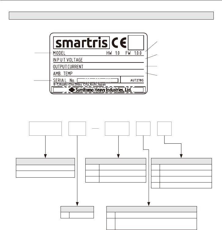
54
10. Connections
10-2 Nameplate and Codes
■
Nameplate
Model
number
Input voltage
QR
code
HW (hardware) version
FW (rmware) version
Output current
Ambient temperature
Serial
number
Fig. 10-1 Nameplate of smartris
■
Nomenclature
Power Capacity
D4 DC48V
Series Name
AG110 (ECO-S, ECO-M, PRO-M)
AG120 (PRO-L)
Drive Unit Capacity
A60 600W (ECO-S)
1A5 1500W (ECO-M, PRO-M)
2A0 2000W (PRO-L)
Safety/Communication Function
0 Without STO/CANopen
1 With STO/CANopen
2 Without STO/Modbus
3 With STO/Modbus
STO : Safety Torque O
Feedback
0 Resolver
K
Absolute Encoder
Absolute Encoder (safety compatible)
1A5AG110 0D4 0

55
11. Cables (Optional)
X1- control cable: supplied by customer
10 cm (Unsheathed cable)
Hausing AMPSEAL 776164-1
Contactor AMPSEAL 770520-1
Back shell AMPSEAL 776463-1
X2- Resolver cable: CABF2C01SS0
Hausing AMPSEAL 776273-1
Contactor AMPSEAL 770520-1
Back shell AMPSEAL 2138530-1
M23 Intercontec A ST A 013 FS 04 41 0235 000
Phoenix CA-12F2N8A8503 - 1619618
Pin 1
Connector pin topology
Included:
cable length = 1 m
Note: Twisted pair (white–brown) (green–yellow) (gray–pink) (blue-red)
776273-1
(14 pins)
Signal Color M23 (12 pins)
1 S2 White 1
2 S1 Green 2
7 S3 Yellow 3
- NC - 4
- NC - 5
6 S4 Brown 6
3 R1 Red 7
5 Shield - 8
12 NTC1a Pink 9
13 NTC1b Gray 10
8 R2 Blue 11
- NC - 12
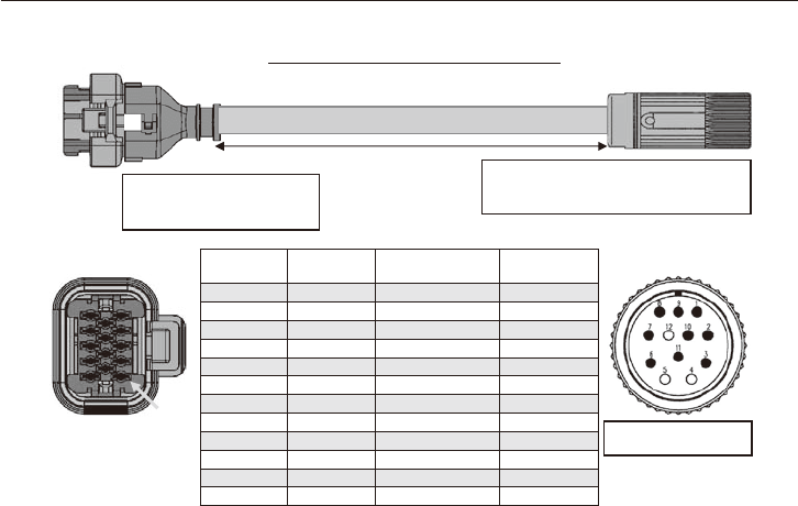
56
11. Cables (Optional)
X2— Absolute encoder cable: CABF6C01SS0
Pin 1
M23 Intercontec A ST A 013 FS 04 41 0235 000
Phoenix CA-12F2N8A8503 - 1619618
Hausing AMPSEAL 776273-1
Contactor AMPSEAL 770520-1
Back shell AMPSEAL 2138530-1
Connector pin topology
Included: cable length = 1 m
Note: Twisted pair (green–brown) (blue–violet) (red–black) (gray–pink) (brown 0.5–white 0.5)
776273-1
(14 pins)
Name Color M23 (12 pins)
1 +SIN Brown 7
6 REF SIN Green 3
2 +COS Blue 8
7 REF COS Violet 4
3 DATA+ Red 5
8 DATA- Black 6
10 +V Brown (0.5 mm
2
) 1
11 GND White (0.5 mm
2
) 2
12 NTC1a Pink 9
13 NTC1b Gray 10
5 Shield - NC
1 +SIN Brown 7

57
12. Warranty
The scope of warranty of our delivered products is limited only to what we manufactured.
Warranty (period and description)
Period
The warranty period applies only to new products and represents 18 months after the ship-
ment or 12 months after the actual operation, whichever is shorter.
Descrip-
tion
If the product failed within the warranty period, in the case where mounting is done prop-
erly, connection and maintenance & administration are followed according to the mainte-
nance manual, and the product is properly run based on the specication on the catalog or
under conditions agreed between us, we will repair or provide an alternative product at our
discretion for free of charge, except the exclusions below.
However, as far as the product is connected with customers' other devices, we will not in-
demnify those expenses on dismounting from/mounting on the devices, etc. and other as-
sociated construction expenses, transportation expenses and opportunity loss and opera-
tion loss the customers suered from, and other indirect damages.
Exclusion
from the
warranty
The following items will be excluded from the warranty:
1. A breakdown resulting from defects in the mounting of the product and connection with
other devices, etc.
2.A breakdown resulting from insucient maintenance & administration and improper
handling of the product, including a case that the product is not stored according to our
dened storage manual.
3. A breakdown resulting from operation which does not fall within our specication and
other operation conditions and use status we hardly can know or a failure caused by the
use of lubricant which we do not recommended.
4. A breakdown resulting from defects, special specication, etc of device prepared and con-
nected by customer.
5. A breakdown resulting from modication or reconstruction of the product.
6. A secondary breakdown occurring in our product due to defects in sequence circuits.
7. A breakdown resulting from defects in parts supplied or specied by customers.
8. A breakdown caused by inevitable force including earthquake, re, ood disaster, salt
damage, gas damage, and lightning strike, etc.
9. Warranty of natural wear and tear, abrasion, and deterioration of consumable parts such
as Aluminum electrolytic capacitor etc. under normal usage.
10. A breakdown caused for reasons not attributable to each of the above item.

Power Transmission & Controls Group
Headquarter ThinkPark Tower, 1-1 Osaki 2-chome, Shinagawa-ku, Tokyo 141-6025, Japan
Specifications, dimensions, and other items are subject to change without prior notice.
No.DM1802E-2.0
EA13 Printed 2021.12
Worldwide Locations
U.S.A
Sumitomo Machinery Corporation of America
(SMA)
4200 Holland Blvd. Chesapeake, VA 23323, U.S.A.
TEL (1)757-485-3355 FAX (1)757-485-7490
Canada
SM Cyclo of Canada, Ltd. (SMC)
1453 Cornwall Road, Oakville, Canada ON L6J 7T5
TEL (1)905-469-1050 FAX (1)905-469-1055
Mexico
SM Cyclo de Mexico, S.A. de C.V. (SMME)
Av. Desarrollo 541, Col. Finsa, Guadalupe,
Nuevo León, México, CP67132
TEL (52)81-8144-5130 FAX (52)81-8144-5130
Brazil
Sumitomo Industrias Pesadas do Brasil Ltda.
(SHIB)
Rodovia do Acucar (SP-075) Km 26
Itu, Sao Paulo, Brasil
TEL (55)11-4886-1000 FAX (55)11-4886-1000
Chile
SM-Cyclo de Chile Ltda. (SMCH)
Camino Lo Echevers 550, Bodegas 5 y 6,
Quilicura, Región Metropolitana, Chile
TEL (56)2-892-7000 FAX (56)2-892-7001
Argentina
SM-Cyclo de Argentina S.A. (SMAR)
Ing Delpini 2230, B1615KGB Grand Bourg,
Malvinas Argentinas, Buenos Aires, Argentina
TEL (54)3327-45-4095 FAX (54)3327-45-4099
Guatemala
SM Cyclo de Guatemala Ensambladora, Ltda.
(SMGT)
Parque Industrial Unisur, 0 Calle B 19-50 Zona 3,
Bodega D-1 Delta Bárcenas en Villa Nueva, Guatemala
TEL (502)6648-0500 FAX (502)6631-9171
Colombia
SM Cyclo Colombia, S.A.S. (SMCO)
Parque Industrial Celta, Km 7.0 Autopista Medellín,
Costado Occidental, Funza, Cundinamarca, Colombia
TEL (57)1-300-0673
Peru
SM Cyclo de Perú, S.A.C (SMPE)
Jr. Monte Rosa 255, Oficina 702, Lima,
Santiago de Surco, Perú
TEL (51)1-713-0342 FAX (51)1-715-0223
Germany
Sumitomo (SHI) Cyclo Drive Germany GmbH
(SCG)
Cyclostraße 92, 85229 Markt Indersdorf, Germany
TEL (49)8136-66-0 FAX (49)8136-5771
Austria
Sumitomo (SHI) Cyclo Drive Germany GmbH
(SCG)
SCG Branch Austria Oce
Gruentalerstraße 30A, 4020 Linz, Austria
TEL (43)732-330958 FAX (43)732-331978
Belgium
Hansen Industrial Transmissions NV (HIT)
Leonardo da Vincilaan 1, Edegem, Belgium
TEL (32)34-50-12-11 FAX (32)34-50-12-20
France
SM-Cyclo France SAS (SMFR)
8 Avenue Christian Doppler, 77700 Serris, France
TEL (33)164171717 FAX (33)164171718
Italy
SM-Cyclo Italy Srl (SMIT)
Via dell' Artigianato 23, 20010 Cornaredo (MI), Italy
TEL (39)293-481101 FAX (39)293-481103
Spain
SM-Cyclo Iberia, S.L.U. (SMIB)
C/Gran Vía Nº 63 Bis, Planta 1, Departamento 1B
48011 Bilbao–Vizcaya, Spain
TEL (34)9448-05389 FAX (34)9448-01550
United Kingdom
SM-Cyclo UK Ltd. (SMUK)
Unit 29, Bergen Way, Sutton Fields Industrial Estate,
Kingston upon Hull, HU7 0YQ, East Yorkshire,
United Kingdom
TEL (44)1482-790340 FAX (44)1482-790321
Turkey
SM Cyclo Turkey Güç Aktarım Sis. Tic. Ltd. Sti.
(SMTR)
Barbaros Mh. Çiğdem Sk. Ağaoğlu, Office Mrk. No:1 Kat:4 D.18
Ataşehir, İstanbul, Turkey
TEL (90)216-250-6069 FAX (90)216-250-5556
India
Sumi-Cyclo Drive India Private Limited (SDI)
Gat No. 186, Raisoni Industrial Park, Alandi Markal Road,
Fulgaon-Pune, Maharashtra, India
TEL (91)96-0774-5353
China
Sumitomo (SHI) Cyclo Drive Shanghai, Ltd.
(SCS)
11F, SMEG Plaza, No. 1386 Hongqiao Road,
Changning District, Shanghai, China 200336
TEL (86)21-3462-7877 FAX (86)21-3462-7922
Hong Kong
SM-Cyclo of Hong Kong Co., Ltd. (SMHK)
Room 19, 28th Floor, Metropole Square, No.2 On
Yiu Street, Shatin, New Territories, Hong Kong
TEL (852)2460-1881 FAX (852)2460-1882
Korea
Sumitomo (SHI) Cyclo Drive Korea, Ltd. (SCK)
Room #913, Royal Bldg, Saemunan-ro 5 gil 19, Jongro-gu,
Seoul, Korea 03173
TEL (82)2-730-0151 FAX (82)2-730-0156
Taiwan
Tatung SM-Cyclo Co., Ltd. (TSC)
22 Chungshan N. Road 3rd., Sec. Taipei, Taiwan 104,
R.O.C.
TEL (886)2-2595-7275 FAX (886)2-2595-5594
Singapore
Sumitomo (SHI) Cyclo Drive Asia Pacic Pte.
Ltd. (SCA)
15 Kwong Min Road, Singapore 628718
TEL (65)6591-7800 FAX (65)6863-4238
Philippines
Sumitomo (SHI) Cyclo Drive Asia Pacic Pte. Ltd.
Philippines Branch Oce (SMPH)
C4 & C5 Buildings Granville Industrial Complex, Carmona,
Cavite 4116, Philippines
TEL (63)2-584-4921 FAX (63)2-584-4922
Vietnam
SM-Cyclo (Vietnam) Co., Ltd. (SMVN)
Factory 2B, Lot K1-2-5, Road No. 2-3-5A,
Le Minh Xuan Industrial Park, Binh Chanh Dist.,
HCMC, Vietnam
TEL (84)8-3766-3709 FAX (84)8-3766-3710
Malaysia
SM-Cyclo (Malaysia) Sdn. Bhd. (SMMA)
No.7C, Jalan Anggerik Mokara 31/56, Kota Kemuning,
Seksyen 31, 40460 Shah Alam, Selangor Darul Ehsan,
Malaysia
TEL (60)3-5121-0455 FAX (60)3-5121-0578
Indonesia
PT. SM-Cyclo Indonesia (SMID)
Jalan Sungkai Blok F 25 No. 09 K, Delta Silicon III,
Lippo Cikarang, Bekasi 17530, Indonesia
TEL (62)21-2961-2100 FAX (62)21-2961-2211
Thailand
SM-Cyclo (Thailand) Co., Ltd. (SMTH)
195 Empire Tower, Unit 2103-4, 21st Floor, South
Sathorn Road, Yannawa, Sathorn, Bangkok 10120,
Thailand
TEL (66)2670-0998 FAX (66)2670-0999
Australia
Sumitomo (SHI) Hansen Australia Pty. Ltd.
(SHAU)
181 Power St, Glendenning, NSW 2761, Australia
TEL (61)2-9208-3000 FAX (61)2-9208-3050
Japan
Sumitomo Heavy Industries, Ltd. (SHI)
ThinkPark Tower, 1-1 Osaki 2-chome, Shinagawa-ku,
Tokyo 141-6025, Japan
TEL (81)3-6737-2511 FAX (81)3-6866-5160
