USER GUIDE

Manufacturer
FUJIFILM SonoSite, Inc.
21919 30th Drive SE
Bothell, WA 98021 USA
T: 1-888-482-9449 or 1-425-951-1200
F: 1-425-951-1201
EC Authorized Representative
Emergo Europe
Molenstraat 15
2513 BH, The Hague
The Netherlands
Australia Sponsor
FUJIFILM SonoSite Australasia Pty Ltd
114 Old Pittwater Road
BROOKVALE, NSW, 2100
Australia
Caution
Federal (United States) law restricts this device to sale by or on the order of a
physician.
ii
SonoSite SII, SonoHD2, SonoMB, SonoSite and the SONOSITE logo are registered and unregistered trademarks of FUJIFILM SonoSite, Inc.
in various jurisdictions.
DICOM is a registered trademark of the National Electrical Manufacturers Association.
FUJIFILM is a registered and unregistered trademark of FUJIFILM Corporation in various jurisdictions.
The FUJIFILM SonoSite ultrasound system(s) referenced in this document may be covered by one or more of the following U.S. patents:
US 8,861,822; US 8,858,436; US 8,834,372; US 8,805,047; US 8,439,840; US 8,398,408; US 8,355,554; US 8,216,146; US 8,213,467; US
8,147,408; US 8,137,278; US 8,088,071; US 8,066,642; US 8,052,606; US 7,819,807; US 7,804,970; US 7,740,586; US 7,686,766; US 7,604,596;
US 7,591,786; US 7,588,541; US 7,534,211; US 7,449,640; US 7,169,108; US 6,962,566; US 6,648,826; US 6,575,908; US 6,569,101; US
6,471,651; US 6,416,475; US 6,383,139; US 6,364,839; US 6,203,498; US 6,135,961; US 5,893,363; US 5,817,024; US 5,782,769; US 5,722,412;
AU: 730822; AU: 727381; CA: 2,372,152; CA: 2,371,711; CN 103237499B; CN 101231457B; CN 98108973.9; CN 98106133.8; CN 97113678.5;
DE 69831698.3; DE 69830539.6; DE 69730563.5; DE 602004027882.3; DE 602004023816.3; DE 60034670.6; DE 60029777.2; EP 1589878; EP
1552792; EP 1180971; EP 0875203; EP 0815793; EP 1180970; EP 0881492; ES 2229318; ES 159878; ES 1552792; ES 0881492; FR 158978; FR
1552792; FR 1180970; FR 0881492; FR 0875203; FR 0815793; GB 158978; GB 1552792; GB 1180971; GB 1180970; GB 0881492; GB
0875203;GB 0815793; IT 1589878; IT 1552792; IT 0881492; IT 0815793; JP 5782428; JP 4696150; KR 532359; KR 528102; NO 326814; NO
326202 and pending.
Part number: P20536-01
Publication date: November 2015
Copyright © 2015 FUJIFILM SonoSite, Inc. All rights reserved.

iii
CONTENTS
Introduction
Conventions .........................................................................................................................................................1
Getting help ......................................................................................................................................................... 2
Getting Started
About the system ...............................................................................................................................................3
License Key ...........................................................................................................................................................3
Preparing the system ........................................................................................................................................ 4
Components and connectors ............................................................................................................... 4
Installing or removing the battery ......................................................................................................5
Using AC power and charging the battery ...................................................................................... 6
Turning the system on or off .................................................................................................................6
Connecting transducers ......................................................................................................................... 7
Inserting and removing USB storage devices ................................................................................. 8
System controls .................................................................................................................................................10
Screen layout .....................................................................................................................................................10
General interaction ..........................................................................................................................................11
Touchpad ...................................................................................................................................................12
Touch screen .............................................................................................................................................13
Control buttons and knobs .................................................................................................................13
Entering text .............................................................................................................................................13
Preparing transducers ....................................................................................................................................15
Acoustic coupling gel ............................................................................................................................15
Intended uses ....................................................................................................................................................16
System Setup
Displaying the settings pages .....................................................................................................................19
Administration setup ......................................................................................................................................19
Security settings ......................................................................................................................................19
User setup ..................................................................................................................................................21
Exporting or importing user accounts ............................................................................................22
Exporting and clearing the Event log ..............................................................................................22
Logging in as user ...................................................................................................................................22
Choosing a secure password ..............................................................................................................23
Annotations settings .......................................................................................................................................23

iv
CONTENTS
Audio, Battery settings ...................................................................................................................................25
Connectivity settings ......................................................................................................................................25
Date and Time settings ..................................................................................................................................27
Display Information settings ........................................................................................................................27
Network Status settings .................................................................................................................................27
OB Calculations settings ................................................................................................................................27
Presets settings .................................................................................................................................................28
System Information settings ........................................................................................................................29
USB Devices settings .......................................................................................................................................29
Limitations of JPEG format ..................................................................................................................30
Imaging
Imaging modes .................................................................................................................................................31
2D imaging ................................................................................................................................................31
M Mode imaging .....................................................................................................................................33
CPD and Color imaging ........................................................................................................................34
Adjusting depth and gain .............................................................................................................................35
Freezing, viewing frames, and zooming ..................................................................................................36
Needle visualization ........................................................................................................................................37
About Steep Needle Profiling technology .....................................................................................37
Needle size and angle ...........................................................................................................................38
Additional recommendations ............................................................................................................39
Centerline ............................................................................................................................................................40
Imaging modes and exams available by transducer ...........................................................................41
Annotating images ..........................................................................................................................................44
Patient information form ...............................................................................................................................46
Patient information form fields ..........................................................................................................47
Images and clips ...............................................................................................................................................49
Saving images and clips .......................................................................................................................49
Reviewing patient exams .....................................................................................................................50
Printing, exporting, and deleting images and clips ....................................................................52
Measurements and Calculations
Measurements ...................................................................................................................................................55
Working with calipers ............................................................................................................................55
Saving measurements ...........................................................................................................................57
2D measurements ...................................................................................................................................58

v
CONTENTS
M-Mode measurements .......................................................................................................................59
Calculations ........................................................................................................................................................61
Calculations menu ..................................................................................................................................61
Performing and saving measurements in calculations .............................................................61
Displaying and deleting saved measurements in calculations ..............................................62
Cardiac calculations ...............................................................................................................................63
Gynecology (Gyn) calculations ...........................................................................................................68
OB calculations ........................................................................................................................................69
Patient report .....................................................................................................................................................72
MSK worksheets ................................................................................................................................................73
References
Measurement accuracy ..................................................................................................................................75
Sources of measurement errors ..................................................................................................................76
Measurement publications and terminology ........................................................................................76
Cardiac references ..................................................................................................................................77
Obstetrical references ............................................................................................................................85
Gestational age tables ...........................................................................................................................86
Ratio calculations ....................................................................................................................................88
General references ..................................................................................................................................89
Troubleshooting and Maintenance
Troubleshooting ...............................................................................................................................................91
Software licensing ............................................................................................................................................93
Maintenance ......................................................................................................................................................94
Cleaning and disinfecting ....................................................................................................................94
Cleaning and disinfecting
Before getting started ....................................................................................................................................95
Determining the required cleaning and disinfecting level ...............................................................96
Spaulding classifications ......................................................................................................................97
Clean and disinfect system and transducer to a high level (semi-critical uses) ........................97
Clean and disinfect system and transducer to a low level (non-critical uses) ......................... 102
Storing the transducer ................................................................................................................................ 104
Transporting the transducer .....................................................................................................................105

vi
CONTENTS
Cleaning the stand ........................................................................................................................................ 106
Safety
Ergonomic safety ........................................................................................................................................... 107
Position the system .............................................................................................................................108
Position yourself ...................................................................................................................................108
Take breaks, exercise, and vary activities ..................................................................................... 109
Electrical safety classification .................................................................................................................... 109
Electrical safety ..............................................................................................................................................110
Equipment safety .......................................................................................................................................... 113
Battery safety .................................................................................................................................................. 114
Clinical safety .................................................................................................................................................. 115
Hazardous materials ..................................................................................................................................... 115
Electromagnetic compatibility ................................................................................................................. 115
Manufacturer’s declaration ............................................................................................................... 116
Labeling symbols ..........................................................................................................................................122
Specifications .................................................................................................................................................. 126
Supported transducers ...................................................................................................................... 126
Imaging modes ..................................................................................................................................... 126
Images and clips storage ................................................................................................................... 127
Accessories .............................................................................................................................................127
Peripherals .............................................................................................................................................. 127
Environmental limits ........................................................................................................................... 127
Electrical specifications ...................................................................................................................... 128
Battery specifications ......................................................................................................................... 128
Standards .........................................................................................................................................................128
Electromechanical safety standards .............................................................................................. 128
EMC standards classification ............................................................................................................ 129
Airborne equipment standards ......................................................................................................129
DICOM standard ................................................................................................................................... 129
HIPAA standard ..................................................................................................................................... 129
Acoustic Output
ALARA principle .............................................................................................................................................131
Applying the ALARA principle ......................................................................................................... 131
Direct controls ....................................................................................................................................... 132
Indirect controls ...................................................................................................................................132

vii
CONTENTS
Receiver controls .................................................................................................................................. 132
Acoustic artifacts ........................................................................................................................................... 133
Guidelines for reducing MI and TI ...........................................................................................................133
Output display ................................................................................................................................................ 136
MI and TI output display accuracy ................................................................................................. 138
Factors that contribute to display uncertainty .......................................................................... 138
Related guidance documents ......................................................................................................... 138
Transducer surface temperature rise ..................................................................................................... 139
Acoustic output measurement ................................................................................................................ 139
In Situ, derated, and water value intensities ..............................................................................140
Tissue models and equipment survey .......................................................................................... 141
Acoustic output tables ................................................................................................................................142
Terms used in the acoustic output tables ................................................................................... 172
Acoustic measurement precision and uncertainty .................................................................. 173
Glossary
Terms ................................................................................................................................................................. 175
Abbreviations ................................................................................................................................................. 177

viii

Conventions 1
CHAPTER 1
Introduction
This SonoSite SII Ultrasound System User Guide provides information on preparing and using
the SonoSite SII ultrasound system and on cleaning and disinfecting the system and
transducers. It also provides system specifications, and safety and acoustic output
information.
The user guide is for a reader familiar with ultrasound techniques. It does not provide
training in sonography or clinical practices. Before using the system, you must have
ultrasound training.
Refer to the applicable FUJIFILM SonoSite accessory user guide for information on using
accessories and peripherals. Refer to the manufacturer’s instructions for specific information
about peripherals.
Conventions
The user guide follows these conventions:
A WARNING describes precautions necessary to prevent injury or loss of life.
A Caution describes precautions necessary to protect the products.
A Note provides supplemental information.
Numbered and lettered steps must be performed in a specific order.
Bulleted lists present information in list format but do not imply a sequence.
Symbols and terms used on the system and transducer are explained in “Labeling symbols”
on page 119 and the “Glossary” on page 169.

2 Getting help Chapter 1
Getting help
In addition to this user guide, the following resources are available:
Instructional videos available on-line.
FUJIFILM SonoSite Technical Support:
Phone
(U.S. or Canada)
877-657-8118
Phone
(outside U.S. or Canada)
425-951-1330, or call your local representative
Fax 425-951-6700
Email ser[email protected]om
Web www.sonosite.com
Europe Service Center Main: +31 20 751 2020
English support: +44 14 6234 1151
French support: +33 1 8288 0702
German support: +49 69 8088 4030
Italian support: +39 02 9475 3655
Spanish support: +34 91 123 8451
Asia Service Center +65 6380-5581

3
CHAPTER 2
Getting Started
About the system
The SonoSite SII ultrasound system is a portable, software-controlled device using all-digital
architecture. The SonoSite SII includes the following configurations:
S-Total
S-Vascular
S-Vet
The system has multiple configurations and feature sets used to acquire and display
high-resolution, real-time ultrasound images. Features available on your system depend on
system configuration, transducer, and exam type.
License Key
A license key is required to activate the software. Refer to “Software licensing” on page 88.
On occasion, a software upgrade may be required. FUJIFILM SonoSite provides a USB device
containing the software. One USB device can upgrade multiple systems.
Basic steps
1 Turn the system on. For power switch location, refer to Figure 2-1 on page 4.
2 Attach a transducer.
3 Tap Patient, and then tap Information.
4 complete the patient information form.
If all imaging modes are licensed, press Mode, and select an imaging mode.
Note By default, the system is in 2D imaging.

4 Chapter 2
Preparing the system
Components and connectors
The back of the system has compartments for the battery and two transducers as well as connectors for USB
devices, power cord, network cable, and more. Refer to Figure 2-1.
Connector block (see detail below)
Battery
Transducer connector ports
USB ports
RJ45 Network
port
HDMI out
DC
power in
Printer
output
Mounting holes
Power switch
Connector block detail
Figure 2-1 System Back

5
Each connector has a symbol that describes its use.
USB
DC input
Composite video out
Print control
Ethernet
HDMI HDMI video out
Installing or removing the battery
WARNING
To avoid injury to the operator and to prevent damage to the ultrasound system,
inspect the battery for leaks prior to installing.
WARNING
To avoid data loss and to conduct a safe system shutdown, always keep a battery in
the system.
To install the battery
1 Ensure the ultrasound system is turned off.
2 Disconnect the power supply.
3 At the back of the system, slide the four prongs on the end of the battery into the slots on the right side of
the battery compartment.

6 Chapter 2
4 Push the battery into the battery compartment and press until the latch engages.
To remove the battery
1 Ensure the ultrasound system is turned off.
2 Disconnect the power supply.
3 Slide the locking lever on the left side of the battery, and lift the battery up.
Using AC power and charging the battery
The battery charges when the system is connected to the AC power supply. A fully discharged battery
recharges in less than five hours.
When the system is connected to AC power, the system can operate and charge the battery at the same time.
Depending on the imaging mode and the display brightness, the system can run on battery power for up to
two hours. When running on battery power, the system may not restart if the battery charge is low. If the
system will not start due to a low battery condition, connect the system to AC power.
WARNING
The equipment shall be connected to a center-tapped single phase supply circuit
when users in the United States connect the equipment to a 240V supply system.
Caution
Verify that the hospital supply voltage corresponds to the power supply voltage
range. Refer to “Electrical specifications” on page 126.

7
To operate the system using AC power
Cautions
Be sure to keep the battery inserted in the system even if the system is connected to
the AC power supply.
1 C
onnect the DC power cable from the power supply to the power connector on the system. Refer to
Figure 2-1 on page 4.
2 Connect the AC power cord to the power supply, and then plug it in to a hospital-grade electrical outlet.
To separate the system (and any connected equipment) from a supply mains
Caution
The equipment is not provided with the AC mains power switch. To disconnect the
equipment from mains, use the appliance coupler or mains plug on the power
supply cord.
Install the ultrasound system in a place where you can easily connect or disconnect
the A
C power cord.
Disconnecting only the DC power cable from the system does not separate the
system from the supply mains.
Disconnect the AC power cord from the stand base.
Turning the system on or off
Caution
Do not use the system if an error message appears on the display. Note the error
code and turn off the system. Call FUJIFILM SonoSite or your local representative.
To turn the system on or off
Press the power switch. Refer to Figure 2-1 on page 4.
To wake up the system
To conserve battery life while the system is on, the system goes into sleep mode if untouched for a preset time.
To adjust the time for sleep delay, refer to “Audio, Battery settings” on page 25.
Press a key, or touch the touchpad.

8
Connecting transducers
WARNING
To avoid injury to the patient, do not place the connector on the patient. The
ultrasound system should only be operatedwhen mounted to the SonoSite SII
stand.
Caution
To avoid damaging the transducer connector, do not allow foreign material in the
connector.
To connect a transducer
1 Pull the transducer latch up, and rotate it clockwise.
2 Align the transducer connector with the connector on the back of the system.
3 Insert the transducer connector into one of the transducer ports on the system.
4 Turn the latch counterclockwise.

9
5 Press the latch down, securing the transducer connector to the system.
To remove a transducer
1 Pull the transducer latch up, and rotate it clockwise.
2 Pull the transducer connector away from the system.
Inserting and removing USB storage devices
Images and clips are saved to internal storage and are organized in a sortable patient list. You can archive the
images and clips from the ultrasound system to a PC using a USB storage device. Although the images and
clips cannot be viewed from a USB storage device on the ultrasound system, you can remove the USB storage
device and view the images on your PC.
You can also import and export user accounts and the Event log using a USB storage device.
There are three USB ports located on the back of the system near the top. For additional USB ports, you can
connect a USB hub into any USB port.
WARNINGS
To avoid damaging the USB storage device and losing patient data from it, observe
the following:
Do not remove the USB storage device or turn off the ultrasound system while the
system is exporting.
Do not bump or otherwise apply pressure to the USB storage device while it is in a
USB port on the ultrasound system. The connector could break.

Caution
If the USB icon does not appear in the system status area on-screen, the USB storage
device may be defective or password-protected. Turn the system off and replace the
device.
Note
The system does not support password-protected USB storage devices. Make sure
that the USB storage device you use does not have password protection enabled.
10 Chapter 2
To insert a USB storage device
Insert the USB storage device into a USB port on the system. Refer to Figure 2-1 on page 4. The USB storage
device is ready when the USB icon appears.
To remove a USB storage device
Removing the USB storage device while the system is exporting may cause the exported files to be corrupted
or incomplete.
1 Wait at least five seconds after the USB animation stops.
2 Remove the USB storage device from the port.

11
System controls
1 Control
knobs
Turn to adjust gain, depth, cine
buffer, brightness, and more,
depending on context. Current
functions appear on-screen above
the knobs.
1
2
4
6
57
8
9
3
9
2 Freeze key Tap to freeze or unfreeze the
image.
3 Touchpad Moves the pointer and other items.
4 Touchpad
key
Works in conjunction with the
t
ouchpad. Tap to activate an item
on-screen. (active only when the
image is frozen.)
5 Print key Available only when a printer is
c
onnected to the system. Tap to
print from a live or frozen scan.
6 Save keys Tap one of these keys to save an
image or a clip
.
7 Image mode Tap one of these keys to change
the imag
ing mode.
8 System
c
ontrols
Change system settings, switch
transducers, add labels, or see
patient information.
9 Image
c
ontrols
Use these to adjust the image.
Screen layout
The layout of the SonoSite SII system screen and the controls that appear on it change according to imaging
mode or the specific task you are performing, such as measuring or annotating. During scanning, the
following information is available:

Patient name
Exam number
Facility
Date and time
Exam type
Transducer
Mechanical &
thermal indexes
Depth
Image status
System
controls
Image controls
12 Chapter 2
Figure 2-2 Screen layout

13
General interaction
Touchpad
The touchpad is an area centered below the screen that you can use as a pointing device. When the touchpad
is active, drag your finger on the surface to move the item on screen.
You can use the touchpad to do the following:
Place labels
Move calipers
Move and shape region of interest (ROI) boxes
Point to a text field in a form
Use the Select key below the touchpad to select or set the item after you have moved it.

14 Chapter 2
Touch screen
As an alternative to the touchpad, you can move some items directly by dragging your finger on the screen
Control buttons and knobs
There are two types of controls on the SonoSite SII system:
Screen controls
The controls that appear on the touchscreen change dynamically depending on the context. For example,
freezing an image may display the controls for zooming, performing measurements, and reviewing the cine
buffer. Only the controls that are available in the current mode or function will appear. To select a control
on the touchscreen, tap it once.
System controls
The buttons and knobs located below the touchscreen are persistent, but some may be disabled during
certain modes or conditions. Controls are lighted when active and dark when disabled. The label for each
knob appears on the screen just above it. The function of each of the knobs may change depending on the
mode or condition.
Entering text
In forms and annotations, you can enter text in text fields using either the on-screen keyboard or an external
USB keyboard connected to a USB port on the system.
If using an external USB keyboard, you enter characters by typing. The TAB key navigates among text fields.
WARNING
To avoid contamination, do not use the USB keyboard supplied by FUJIFILM
SonoSite in a sterile environment. The USB keyboard is not sterilized and cannot
withstand sterilization.

15
To enter text in text fields using the on-screen keyboard
1 Using the touchpad or the touchscreen, select a text field.
The on-screen keyboard appears with the text field at the top.
2 On the touchscreen, tap each character you want to enter.
The Äñ key displays and hides international characters.
The Symbols key displays symbols and punctuation.
The Caps Lock key turns capital letters on and off.
The Shift key turns capital letters on or off for the next letter entered.
The Delete key deletes the character right of the pointer.
The backspace key deletes the character to the left of the pointer.
3 To navigate among text fields:
Tap Next to advance to the next field.
Tap Prev to return to the previous field.
4 To exit the keyboard, click one of the following:
OK to save changes.
2D to save changes and display 2D imaging.

16 Chapter 2
Preparing transducers
WARNINGS
Some transducer sheaths contain natural rubber latex and talc, which can cause
allergic reactions in some individuals. Refer to 21 CFR 801.437, User labeling for
devices that contain natural rubber.
Some gels and disinfectants can cause an allergic reaction on some individuals.
Cautions
To avoid damage to the transducer, use only gels recommended by FUJIFILM
SonoSite. Using gels other than the one recommended by FUJIFILM SonoSite can
damage the transducer and void the warranty. If you have questions about gel
compatibility, contact FUJIFILM SonoSite or your local representative.
FUJIFILM SonoSite recommends that you clean and disinfect transducers after each
use. Refer to “Cleaning and disinfecting” on page 91.
Acoustic coupling gel
Acoustic coupling gel must be used during exams. Although most gels provide suitable acoustic coupling,
some gels are incompatible with some transducer materials. FUJIFILM SonoSite recommends Aquasonic
®
gel
and provides a sample with the system.
For general use, apply a liberal amount of gel between the transducer and the body. For invasive procedures,
apply a transducer sheath.
WARNING
To prevent contamination, the use of sterile transducer sheaths and sterile coupling
gel is recommended for clinical applications of an invasive nature. Do not apply the
transducer sheath and gel until you are ready to perform the procedure.
To apply a transducer sheath
To lessen the risk of contamination, install the sheath only when you are ready to perform the procedure.
1 Place gel inside the sheath.
2 Insert the transducer into the sheath.
3 Pull the sheath over the transducer and cable until the sheath is fully extended.
4 Secure the sheath using the bands supplied with the sheath.
Check for and eliminate bubbles between the face of the transducer and the sheath.
Note
Bubbles between the face of the transducer and the sheath may affect the ultrasound
image.

17
5 Inspect the sheath to ensure that there are no holes or tears.
Intended uses
The SonoSite SII ultrasound system is a general purpose ultrasound system intended for use by qualified
physicians and healthcare professionals for evaluation by ultrasound imaging or fluid flow analysis of the
human body.
The system is used with a transducer attached and is powered either by battery or by AC electrical power. The
clinician is positioned beside the patient and places the transducer onto (or into, for invasive procedures) the
patient’s body where needed to obtain the desired ultrasound image.
For the intended transducer for each exam type, refer to “Imaging modes and exams available by
transducer” on page 41.
The system transmits ultrasound energy into the patient’s body to obtain ultrasound images as described
below.
Abdominal Imaging Applications
You can assess the liver, kidneys, pancreas, spleen, gallbladder, bile ducts, transplanted organs, abdominal
vessels, and surrounding anatomical structures for the presence or absence of pathology transabdominally.
Cardiac Imaging Applications
You can assess the heart size and function, cardiac valves, great vessels, visualize blood flow through cardiac
valves, and assess for the presence or absence of pathology. In addition, you can identify the presence and
location of fluid around the heart and lungs used to assist in pericardiocentesis and thoracentesis procedures.
You can detect normal lung motion for the presence or absence of pathology.
Gynecology and Infertility Imaging Applications
You can assess the uterus, ovaries, adnexa, and surrounding anatomical structures for the presence or absence
of pathology transabdominally or transvaginally.
Interventional Imaging Applications
You can use the system to provide ultrasound guidance for biopsy and drainage procedures, vascular line
placement, peripheral nerve blocks, amniocentesis, and other obstetrical procedures and to provide
assistance during abdominal, breast, and neurological surgery.

18 Chapter 2
Obstetrical Imaging Applications
You can assess the fetal anatomy, viability, estimated fetal weight, gestational age, amniotic fluid, and
surrounding anatomical structures for the presence or absence of pathology transabdominally or
transvaginally. CPD and Color imaging are intended for high-risk pregnant women. High-risk pregnancy
indications include, but are not limited to, fetal hydrops, placental abnormalities, as well as maternal
hypertension, diabetes, and lupus.
WARNINGS
To prevent injury or misdiagnosis, do not use this system for Percutaneous
Umbilical Blood Sampling (PUBS) or in vitro Fertilization (IVF) The system has not
been validated to be proven effective for these two uses.
CPD or Color images can be used as an adjunctive method, not as a screening tool,
f
or the detection of structural anomalies of the fetal heart, and as an adjunctive
method, not as a screening tool, for the diagnosis of Intrauterine Growth
Retardation (IUGR)
Pediatric and Neonatal Imaging Applications
You can assess the pediatric and neonatal abdominal, pelvic, and cardiac anatomy, pediatric hips, neonatal
head, and surrounding anatomical structures for the presence or absence of pathology.
Superficial Imaging Applications
You can assess the breast, thyroid, testicle, lymph nodes, hernias, musculoskeletal structures, soft tissue
structures, ophthalmic structures, and surrounding anatomical structures for the presence or absence of
pathology. You can use the system to provide ultrasound guidance for biopsy and drainage procedures,
vascular line placement, and peripheral nerve blocks.
WARNING
To avoid injury to the patient, use only an Ophthalmic (Oph) exam type when
performing imaging through the eye. The FDA has established lower acoustic
energy limits for ophthalmic use. The system will not exceed these limits only if the
Oph exam type is selected.
Vascular Imaging Applications
You can assess the carotid arteries, deep veins, and arteries in the arms and legs, superficial veins in the arms
and legs, great vessels in the abdomen, and various small vessels feeding organs for the presence or absence
of pathology.
Contraindications
The SonoSite SII ultrasound system has no known contraindications.

19
CHAPTER 3
System Setup
The setup pages let you customize the system and set preferences.
Displaying the settings pages
To display a settings page
1 Tap Settings.
2 Under Settings Pages, select the page you want by tapping it.
3 To return to imaging from a setup page, tap Done.
Administration setup
On the Administration settings page, you can configure the system to require users to log
in and enter passwords. Required login helps protect patient data. You can also add and
delete users, change passwords, import and export user accounts, and display the Event log.
Security settings
WARNING
Health care providers who maintain or transmit health information
are required by the Health Insurance Portability and Accountability
Act (HIPAA) of 1996 and the European Union Data Protection
Directive (95/46/EC) to implement appropriate procedures: to
ensure the integrity and confidentiality of information; to protect
against any reasonably anticipated threats or hazards to the
security or integrity of the information or unauthorized uses or
disclosures of the information.
Security settings on the system allow you to meet the applicable security requirements
listed in the HIPAA standard. Users are ultimately responsible for ensuring the security and
protection of all electronic protected health information collected, stored, reviewed, and
transmitted on the system.

20 Chapter 3
To log in as Administrator
1 On the Administration settings page, type Administrator in the Name box. Refer to “Entering text” on
page 14.
Note The entries for Name and Password are case-sensitive.
2 Type the administrator password in the Password box.
If you don’t have the administrator password, contact FUJIFILM SonoSite. Refer to “Getting help” on
page 2.
3 Tap Login.
To log out as Administrator
Turn off or restart the system.
To require user login
You can set the system to display the User Login screen at startup.
1 Log in as Administrator.
2 In the User Login list, tap On.
On requires a user name and password at startup.
Off allows access to the system without a user name and password.
To change the administrator password or let users change passwords
1 Log in as Administrator.
2 Under User List, tap Administrator.
3 To change the administrator password:
a Under User Information, in the Password box, type the new password.
b In the Confirm box, type the new password again. For more information about passwords, see
“Choosing a secure password” on page 23.
4 To let users change their passwords, select the Password changes check box.
5 Tap Save.

21
User setup
To add a new user
1 Log in as Administrator.
2 Tap New.
3 Under User Information, fill in the Name, Password, and Confirm boxes. For more information about
passwords, see “Choosing a secure password” on page 23.
(Optional) In the User box, type the user’s initials to display them in the patient header and the User
box in the patient information form.
(Optional) Select the Administration Access check box to allow access to all administration privileges.
4 Tap Save.
To modify user information
1 Log in as Administrator.
2 Under User List, tap the user.
3 Under User Information, make changes as desired.
4 Tap Save. Any change to the user name replaces the previous name.
To delete a user
1 Log in as Administrator.
2 Under User List, tap the user.
3 Tap Delete.
4 Tap Ye s.
To change a user password
1 Log in as Administrator.
2 Under User List, tap the user.
3 Type the new password in the Password box and Confirm box.
4 Tap Save.

22 Chapter 3
Exporting or importing user accounts
The export and import commands let you configure multiple systems and back up user account information.
To export user accounts
1 Insert a USB storage device. For more information, see “Inserting and removing USB storage devices” on
page 9.
2 Log in as Administrator.
3 Tap Export. A list of USB devices appears.
4 Tap the USB storage device, and then tap Export.
All user names and passwords are copied to the USB storage device. Passwords are encrypted.
To import user accounts
1 Insert the USB storage device that contains the accounts. For more information, see “Inserting and
removing USB storage devices” on page 9.
2 Log in as Administrator.
3 Tap Import.
4 Tap the USB storage device, and then tap Import.
5 Tap Restart in the dialog box that appears. The system restarts.
All user names and passwords on the system are replaced with the imported data.
Exporting and clearing the Event log
The Event log collects errors and events and can be exported to a USB storage device and read on a PC.
Logging in as user
If user login is required, the User Login screen appears when you turn on the system. For more information,
see “To require user login” on page 20.
To log in as user
1 Turn on the system.
2 In the User Login screen, type your name and password, and tap OK.

23
To log in as guest
Guests can scan but can’t access system setup and patient information.
1 Turn on the system.
2 In the User Login screen, tap Guest.
To change your password
1 Turn on the system.
2 In the User Login screen, tap Password.
3 Type your old and new passwords, confirm the new password, and then tap OK.
Choosing a secure password
To ensure security, choose a password that contains uppercase characters (A-Z), lowercase characters (a-z),
and numbers (0-9). Passwords are case-sensitive.
Annotations settings
On the Annotations settings page, you can customize predefined labels and set the preference for managing
text when unfreezing images.
For instructions to annotate images, refer to “Annotating images” on page 44.
To predefine a label group
You can specify which labels are available for an exam type when annotating an image. Refer to “To place text
on an image” on page 45.
1 On the Annotations settings page, in the Exam list, select the exam type that includes the labels you want
to specify.
2 Choose the label group associated with that exam. Next to Group, select A, B, or C. The preset labels for the
selected group appear in the scroll list.
3 To add a custom label to the group:
a Tap <New> in the scroll list.
b Type the label in the Tex t box.
c Tap Add.

24 Chapter 3
4 To rename a label:
a Tap the label
b Type the new name in the Tex t box
c Tap Rename.
5 To move a label within the group:
a Tap the label
b Tap the up or down arrow.
6 To delete a label from a group, tap the label, and then tap Delete.
Refer to also “Entering text” on page 14.
To specify text retention when unfreezing
You can specify which text to keep when you unfreeze an image or change the imaging layout.
In the Unfreeze list on the Annotations settings page, select Keep All Text, Keep Home Text, or Clear
All Text.
Note
The default setting is Keep All Text. For information on setting the home position,
refer to “To place an arrow on an image” on page 45.
To export predefined label groups
1 Insert a USB storage device.
2 On the Annotations settings page, tap Export. A list of USB devices appears.
3 Select the USB storage device, and then tap Export.
A copy of all predefined label groups for all exams saves to the USB storage device.
To import predefined label groups
1 Insert the USB storage device that contains the label groups.
2 On the Annotations settings page, tap Import.
3 Select the USB storage device, and then tap Import.
4 Tap OK in the dialog box that appears.
All predefined label groups for all exams are replaced with those from the USB storage device.

25
Audio, Battery settings
On the Audio, Battery settings page, you can select options from the following lists:
Key click
Controls whether the controls make a clicking sound when tapped.
Choose either On or Off.
Beep alert
Controls whether the system beeps when saving, warning, starting, or shutting down.
Choose either On or Off.
Sleep delay
Specifies the period of inactivity before the system goes into sleep mode. Set to either five minutes, ten
minutes, or Off. Turning off the sleep delay prevents the system from going into sleep mode.
Choose either Off, 5, or 10.
Power delay
Specifies the period of inactivity before the system automatically turns off. Set to either 15 minutes, 30
minutes, or Off. Turning off the power delay prevents the system from turning itself off.
Choose either Off, 15, or 30.
Connectivity settings
On the Connectivity settings page, select options for using devices and for alerts when internal storage is full.
You also import wireless certificates and specify settings (including Transfer Mode and Location) for PDAS™
Image Manager and DICOM
®
, which are optional features. Refer to the PDAS and DICOM documentation.
To configure the system for a printer
1 Set up the printer hardware. Refer to instructions included with the printer or stand.
2 On the Connectivity settings page, choose a printer from the Printer menu.
3 Plug the printer cable into the video output on the system.
To configure the system for a DVD recorder
1 On the Connectivity settings page, in the Video Mode list, click the video standard: NTSC or PAL.

26 Chapter 3
2 Restart the system.
3 Plug the DVD recorder cable into the video output on the system.
To connect to PDAS
1 On the Connectivity settings page, choose PDAS from the Transfer mode list.
2 Restart the system.
3 On the Connectivity settings page, tap PDAS setup.
4 On the PDAS page, choose the PDAS account you want to use, and then tap Save.
5 To create a new account:
a Tap New.
b Enter the network settings for your new PDAS account. Work with your network administrator to obtain
the correct information.
c Tap Save.
6 To import the PDAS connection information:
a Insert the USB storage device that contains the PDAS connection information.
b On the PDAS page, tap Import.
c Choose the USB storage device, and then tap Import.
7 To export your PDAS connection information:
a Insert a USB storage device.
b On the PDAS page, tap Export.
c Choose the USB storage device, and then tap Export.
8 Tap Done.
To connect to DICOM
1 On the Connectivity settings page, choose DICOM from the Transfer mode list.
2 Restart the system.
3 On the Connectivity settings page, tap DICOM setup.
4 On the DIC
OM page, choose a location, and then choose the DICOM server you want to connect to.

27
5 Tap Verify and check that communication with the DICOM server is successful.
6 Tap Done.
To receive storage alerts
On the Connectivity settings page, select Internal Storage Capacity Alert. The system displays a message
if internal storage is near capacity when you end an exam.
Date and Time settings
To set the date and time
1 On the Date and Time settings page, do the following:
a In the Date box, type the current date. Refer to “Entering text” on page 14.
b In the Time box, type the current time in 24 hour format (hours and minutes).
Display Information settings
On the Display Information settings page, you can specify which details appear on-screen during imaging.
For example, you can help protect patient privacy by not displaying the patient name and ID on the screen.
You can select check boxes in the following sections:
Patient Header
Information from the patient information form. Refer to “Patient information form” on page 46.
Mode Data
Imaging information.
System Status
Power, battery, connectivity, and similar information.
Network Status settings
The Network Status settings page displays information on system IP address, Location, Ethernet MAC
address, and the wireless connection if any.
OB Calculations settings
On the OB Calculations settings page, you can select authors for OB gestational calculation tables. Refer to
also “OB calculations” on page 69.

28 Chapter 3
To specify gestational age
On the OB Calculations settings page, select the desired OB authors (or select None) in the measurement
lists under Gestational Age. Selecting an author places the associated measurement on the calculations
menu.
Presets settings
The Presets settings page enables you to choose some general preferences. Use the following information to
help you choose the presets that are right for you:
Depth Markers
Type 1
Displays an unnumbered depth scale to the right of the image, with the maximum depth number in the
lower right screen.
Type 2
Displays a numbered depth scale to the right of the image.
Thermal Index
Choose between TIS, TIB, or TIC.
By default, this setting is based on exam type: OB is TIB, and all others are TIS.
Clip Length
Choose the maximum clip length. Clip lengths are in seconds.
Units
Choose the units you want to use for patient height and weight in cardiac exams: in/ft/lbs or cm/m/kg.
Language
You can change the language used in the system interface. Changing the language requires restarting the
system.
Auto save Pat. Form
When turned on, automatically saves the patient information form as an image in the patient’s file.
Save Key:
Determines the behavior of the Save key:
Image Only
Saves the image to internal storage.

29
Image/Calcs
Saves the image to internal storage and saves the current calculation to the patient report.
Duplex
Specifies the screen layout when displaying M Mode trace:
1/3 2D, 2/3 Trace
Divides the screen so that the top 1/3 shows the 2D image, while the bottom 2/3 displays the trace.
1/2 2D, 1/2 Trace
The 2D image and the trace each occupy 1/2 of the screen.
Full 2D, Full Trace
You can switch between the two full-screen views.
System Information settings
The System Information settings page displays system hardware and software versions, patents, and license
information.
To enter a license key, see “To enter a license key” on page 89.
To display patents
On the System Information settings page, press Patents.
USB Devices settings
On the USB Devices settings page, you can view information about connected USB devices, including space
availability. You can also specify a file format for images in patient exams that you export to a USB storage
device.
To specify a file format for exported images
The image format you specify affects only still images. Clips export in H.264 video format saved as MP4 files.
To export images
1 On the USB Devices setup page, click Export.
2 Under PDAS, select an image format. For JPEG image format, also select a JPEG compression.
Note A high compression has a smaller file size. but less detail.
3 Select a sort order under Sort By. The sort order specifies how exported files are organized.

30 Chapter 3
4 To return to the previous screen, click Devices.
To include private tags
1 If you use DICOM export type and a FUJIFILM SonoSite software product, include private tags on the
images.
2 On the USB Devices setup page, select Include private tags.
Note
Because the tags may be incompatible with some earlier archivers, keep this check
box unselected unless you use FUJIFILM SonoSite software products. For more
information, refer to the ultrasound system’s DICOM conformance statement.
Limitations of JPEG format
When transferring or exporting images in JPEG format, the system uses lossy compression. Lossy compression
may create images that have less absolute detail than BMP format and that don’t render identically to the
original images.
In some circumstances, lossy-compressed images may be inappropriate for clinical use. For example, if you use
images in SonoCalc
®
IMT software, you should transfer or export them using BMP format. SonoCalc IMT
software uses a sophisticated algorithm to measure images, and lossy-compression may cause errors.
For more information on using lossy-compressed images, consult the industry literature, including the
following references:
“Physics in Medicine and Biology, Quality Assessment of DSA, Ultrasound and CT Digital Images Compressed
with the JPEG Protocol,” D Okkalides et al. 1994 Phys Med Biol 39 1407-1421 doi: 10.1088/0031-9155/39/9/
008 www.iop.org/EJ/abstract/0031-9155/39/9/008
“Canadian Association of Radiologists, CAR Standards for Irreversible Compression in Digital Diagnostic
Imaging within Radiology,” Approved: June 2008. www.car.ca/Files/%5CLossy_Compression.pdf

31
CHAPTER 4
Imaging
Imaging modes
The SonoSite SII system has a high-performance LCD and advanced image-optimization
technology that simplifies user controls. Available imaging modes depend on the
transducer and exam type. Refer to “Imaging modes and exams available by transducer”
on page 41.
2D imaging
2D is the system's default imaging mode. The system displays echoes in two dimensions by
assigning a brightness level based on the echo signal amplitude. To achieve the best image
quality, properly adjust the gain and depth settings, viewing angle, and exam type. For more
information about presets, see “Presets settings” on page 28.
To display the 2D image
1 Do one of the following:
Turn on the system.
From another imaging mode, tap 2D.
2 Adjust controls. For more information, see “2D controls.”
2D controls
Note
If the control you want does not appear on the screen, tap the
More Controls arrow to view additional controls.

32 Chapter 4
Refer to also “Adjusting depth and gain” on page 35.
Table 4-1: 2D controls
Control Description
Gain
Adjusts the image brightness through signal amplification. To change the gain, rotate
the Gain knob.
Depth Adjusts the depth of the image. To change the depth, rotate the Depth knob.
Auto Gain
The gain adjusts automatically each time you press the key.
To adjust gain manually, see “Adjusting depth and gain” on page 35.
Optimize
Settings are as follows:
Res provides the best possible resolution.
Gen pr
ovides a balance between resolution and penetration.
Pen provides the best possible penetration.
Some of the parameters optimized to provide the best image include focal zones,
aperture size, frequency (center and bandwidth), and waveform. They cannot be
adjusted by the user.
THI
Turns Tissue Harmonic Imaging on and off.
When on, THI appears in the mode data area. This feature depends on transducer and
exam type.
SonoMB
Turns SonoMB
®
multi-beam imaging on and off. When on, MB appears in the mode data
area. This feature depends on transducer and exam type.
Orientation
Select from four image orientations: U/R (Up/Right), U/L (Up/Left), D/L (Down/Left), D/R
(Down/Right).
Guide
Turns needle guidelines on. Guidelines can be used for needle guidance, and depend on
transducer type.
If using a variable angle needle guide, tap Guide. To select the angle, tap A, B, or C. To
change the depth, move your finger on the touchscreen or the touchpad. To turn needle
guidelines off, tap A, B, or C until the word Guide appears..
Dual
Displays side-by-side 2D images.
Tap Dual, and then tap Update to display the second screen and to toggle between the
screens.
To return to full-screen 2D imaging, tap Off.
Monitor
Adjusts the screen brightness. Tap the button to show more controls, and then turn
the Monitor knob. The default brightness value is 8, but settings range from 1 to 10.
The screen brightness affects battery life. To conserve battery life, adjust brightness to a
lower setting.

33
M Mode imaging
Motion mode (M Mode) is an extension of 2D. It provides a trace of the 2D image displayed over time. A single
beam of ultrasound is transmitted, and reflected signals are displayed as dots of varying intensities, which
create lines across the screen.
To display the M-line
1 T
ap M.
Note If the M-line does not appear, make sure that the image isn’t frozen.
2 Drag y
our finger on either the touchpad or the touchscreen to position the M-line where desired.
3 A
djust controls as desired.
4 Tap M to start the M Mode trace.
M Mode controls.
Table 4-2: M Mode controls
Control Description
Gain Adjusts the signal amplification. To change the gain, rotate the Gain knob.
Depth Adjusts the depth of the scan. To change the depth, rotate the Depth knob.
M line
position
Defines the area of interest so that movement can then be traced over time. To change
the position of the M line, drag your finger on the touchpad or the touchscreen.
Scan speed Controls the speed of the trace. Your options are Fast, Med, and Slow.
To display the M Mode trace
1 Display the M line.
2 Adjust the depth if necessary to show the structure you want to scan. For more information, see “To adjust
depth” on page 35.
3 Using the touchpad or the touchscreen, move the M line to pass through the structures you want to scan.

34 Chapter 4
4 To begin the trace, tap M.
A trace window appears. For information about changing the duplex layout, see “Presets settings” on
page 28.
Note
The time scale above the trace has small marks at 200 ms intervals and large marks
at one
-second intervals.
5 T
o change the sweep speed, tap Slow, Med, or Fast to cycle through each sweep speed.When the trace is
frozen, you can change between the M-line and M-mode trace by tapping Update M or Update 2D.
CPD and Color imaging
Color power Doppler (CPD) is used to visualize the presence of detectable blood flow. Color is used to visualize
the presence, velocity, and direction of blood flow in a wide range of flow states.
To display the CPD or Color image
1 Tap C to enter Color mode.
A ROI box appears in the center of the 2D image. The current selection (Color or CPD) appears in the mode
data area.
Note
In Color imaging, the Color indicator bar on the upper left-hand screen displays
velocity in cm/s.
2 To change to CPD, tap CPD.
3 Using the touchpad or the touchscreen, you can change the position or size of the ROI box as needed.
Tapping Position or Size, or tapping , switches between position and size. When resizing, the outline
is a dashed line.
4 Adjust controls as desired. Refer to “CPD and Color controls.”
CPD and Color controls
Table 4-3: CPD and Color controls
Control Description
Flow
Sensitivity
Choose one of the following:
• Flow Low optimizes the system for low flow states.
• Flow Med optimizes the system for medium flow states.
• F
low High optimizes the system for high flow states.

35
Adjusting depth and gain
To adjust depth
You can adjust the depth in all imaging modes except M Mode. The vertical depth scale is marked in 0.5 cm,
1 cm, and 5 cm increments, depending on the depth.
Turn the Depth knob:
Clockwise
Increases the displayed depth.
Counter-clockwise
Decreases the displayed depth.
To change the style of depth markers, see “Presets settings” on page 28.
To adjust gain automatically
To adjust gain automatically in 2D, you can tap the Auto Gain button. For more information, see “2D
controls” on page 31.
PRF Scale
Select the desired PRF (pulse repetition frequency) Scale setting by tapping PRF, and
then tapping either the up or down arrow.
The available PRF Scale settings depend on the Flow Sensitivity setting.
Available on select transducers.
Invert
Switches the displayed direction of flow.
Available in Color imaging.
Steering
If using a linear array transducer, tap the Steering button to change the steering angle
(for example: -15, 0, or +15).
Wall Filter
A high wall filter can reduce excessive motion or noise, while a low wall filter displays
more of the raw signal.
Choose one of the following:
• WF Low
• WF Med
• WF High
Variance (Cardiac exam only) Turns variance on and off.
Table 4-3: CPD and Color controls
Control Description

36 Chapter 4
To adjust gain manually
1 Turn the Gain knob:
Clockwise
Raises the gain.
Counter-clockwise
Lowers the gain.
2 To switch to near or far gain, tap the Gain button, or press the Gain knob.
Freezing, viewing frames, and zooming
To freeze or unfreeze an image
Tap the Freeze button ( ).
On a frozen image, the cine icon and frame number appear above the left knob.
To move forward or backward in the cine buffer
On a frozen image, turn the Cine knob. The total number of frames appears next to the cine icon. The
number changes to the current frame number as you move forward or backward.
WARNING
To avoid loss of data, be careful not to touch the Freeze button () while turning the
Cine knob.
Note You can also use the touchpad to move the cine.
To zoom in on an image
You can zoom in 2D or Color imaging. You can freeze or unfreeze the image or change the imaging mode at
any time while zooming.
1 Tap Zoom. A ROI box appears.
2 Using the touchpad or the touchscreen, position the ROI box as desired.
3 Tap Zoom. The image in the ROI box is magnified by 100%.
4 (Optional) If the image is frozen, use the touchpad or the touchscreen to pan the image up, down, left, and
right.
5 To exit zoom, tap Zoom Off.

37
Needle visualization
WARNINGS
To avoid incorrect needle placement when Steep Needle Profiling (SNP) is on:
Use only FUJIFILM SonoSite or CIVCO approved needle guides, brackets, supplies,
c
omponents, and accessories. Other brands may not properly fit FUJIFILM
SonoSite transducers.
Use only needle guides compatible with the transducers listed in Table 4-4,
“Transducers and exam types available with SNP” on page 37.
Using movement and fluid injection, verify the needle-tip location and trajectory.
Steep Needle Profiling technology enhances linear structures within a selected
angle range on the ultrasound plane. Linear structures outside the selected angle
range or the ultrasound plane—such as a bent needle—may be less apparent.
Note that linear structures are enhanced only in an outlined portion of the image.
The area outside the outline remains unchanged.
Note that the beam divergence of a curved array transducer may prevent a
segment of the needle shaft from showing in the image. The needle tip may not
show.
About Steep Needle Profiling technology
The SNP control turns on Steep Needle Profiling technology (formerly SonoMBe™ imaging), which enhances
linear structures within a selected angle range and can facilitate needle guidance during catheter placement
and nerve-block procedures. A three- or four-sided outline indicates the enhancement area as shown in
Figure 4-1 on page 38.
For curved array transducers, Steep Needle Profiling technology can help identify the direction of the needle,
although only segments of the needle shaft may show in the image. See Figure 4-2 on page 38. Use
movement and fluid injection to help verify the needle-tip location.
The SNP control is available in 2D full-screen imaging only and on the following:
Table 4-4: Transducers and exam types available with SNP
Transducer Arterial Breast Musculoskeletal Nerve
Small
Parts
Venous
rC60xi standard/armored
HFL38xi
HFL50x
HSL25x
L25x

38 Chapter 4
Figure 4-1 Image with SNP on (linear transducer)
Figure 4-2 When using a curved-array transducer, only segments of the needle shaft may appear.
Needle size and angle
Use a 17-gauge to 25-gauge needle (recommended). Enhancement results can depend on the type and brand
of needle used. For more information, consult the medical literature on needle visibility in ultrasound-guided
procedures.
You can angle the needle up to 50° from the transducer surface as shown in Figure 4-3 on page 39. Beyond
50°, the needle may be less enhanced.
WARNING
To avoid patient injury when using a multi-angle bracket, make sure that the same
angle is selected (A, B, or C) on both the bracket and the ultrasound system.
L38xi standard/armored
Needle shaft
Outlined area
enhanced by SNP
Dotted line
Unenhanced area
Upper needle shaft
Segment of needle
shaft not shown
(depends on specific
image)
Needle tip
Table 4-4: Transducers and exam types available with SNP
Transducer Arterial Breast Musculoskeletal Nerve
Small
Parts
Venous

Note
Steep Needle Profiling technology is intended for in-plane procedures only. Steep
Needle Profiling technology has little or no benefit to out-of-plane procedures.
Needle
Transducer
39
Figure 4-3 For best results, angle the needle only up to 50° from the transducer surface.
SNP subcontrols
When Steep Needle Profiling technology is on, additional controls are available:
L/R Flip flips the affected area (the outline) horizontally on the image. For reorienting the entire image, use
the orientation control. See “2D controls” on page 31.
Shallow, Medium, or Steep sets the outline’s sloped edge, which is indicated by a dotted line. The current
selection is highlighted.
Linear transducer: Use whichever setting best provides a perpendicular intersection with the dotted
line. Within the enhancement area, the more perpendicular that a linear structure is to the dotted line,
the more it is enhanced. Similarly, the less perpendicular (and more parallel) that a linear structure is to
the dotted line, the less it is enhanced.
Curved array transducer: For a linear structure angled 30° or less from the transducer surface, use
Shallow for best enhancement. For a linear structure angled 30-40°, use Medium. For a linear structure
angled 40° or greater, use Steep.
Off turns off SNP. Temporarily turning off SNP can help you identify artifacts and other structures not of
interest.
Note If Steep Needle Profiling technology is on, the MB control is unavailable.
Additional recommendations
Avoid setting the gain too high when using Steep Needle Profiling technology, as unnecessarily high gain can
cause artifacts in the image. Also, respiratory and cardiac movement in the image may cause bright pulsating
artifacts.

40 Chapter 4
Centerline
The centerline graphic aligns with the center mark of the transducer and serves as a reference mark for the
center of the displayed image.
When using the Centerline feature as a reference during a freehand procedure, be aware that the centerline
r
epresents only the center of the ultrasound image and is not an accurate predictor of the path the needle will
take.
Ensure orientation
marks on the screen
and transducer are
on the same side
Scan plane
Centerline
Anatomical
feature
Figure 4-4 Relationship of the centerline graphic to the transducer and the ultrasound image.
Small tilts or rotations of the transducer can affect the relationship between any external reference points and
the anatomy that appears on the ultrasound image.

41
Figure 4-5 Relationship of the ultrasound image to the transducer angle or tilt.
Imaging modes and exams available by transducer
WARNINGS
To prevent misdiagnosis or harm to the patient, understand your system’s
capabilities prior to use. The diagnostic capability differs for each transducer,
exam type, and imaging mode. In addition, transducers have been developed
to specific criteria depending on their physical application. These criteria
include biocompatability requirements.
To avoid injury to the patient, use only an Ophthalmic (Oph) when performing
imaging through the eye. The FDA has established lower acoustic energy limits
for ophthalmic use. The system will not exceed these limits only if the Oph
exam type is selected.
The transducer you use determines which exam types are available. In addition, the exam type you select
determines which imaging modes are available.
To select a transducer
1 Tap Transducer.
The menu showing the current active transducer appears.
2 If another transducer is connected, you can change to that one by tapping Switch.

42 Chapter 4
To change the exam type
Do one of the following:
Tap Transducer, and then choose an exam type from the list of available exams.
Tap Patient, and then tap Information. Choose an exam type from the Type list in the Exam window.
Refer to “Patient information form” on page 46.
Available imaging modes and exams
Table 4-5: Imaging modes and exams available by transducer
Transducer
Exam type
a
Imaging mode
2D
b
CPD
c
Color
c
C11x
Abd
Art
Neo
Nrv
Ven
rC60xi standard/
armored
Abd
Gyn
Nrv
Msk
OB
HFL38xi
Art
Bre
Lung
Msk
Nrv
SmP
Ven

43
HFL50x
Bre
Msk
Nrv
SmP
HSL25x
Art
Lung
Msk
Nrv
Oph
Sup
Ven
ICTx
Gyn
OB
L25x
Art
Lung
Msk
Nrv
Oph
Sup
Ven
Table 4-5: Imaging modes and exams available by transducer
Transducer
Exam type
a
Imaging mode
2D
b
CPD
c
Color
c

44 Chapter 4
Annotating images
You can annotate live images as well as frozen images. (You cannot annotate a saved image.) You can place
text (including predefined labels), an arrow, or a pictograph. To set preferences for annotations, refer to
“Annotations settings” on page 23.
L38xi standard/
armored
Art
Lung
Nrv
SmP
Ven
P10x
Abd
Crd
Neo
P11x
d
Art
Ven
rP19x standard/
armored
Abd
Crd
Lung
OB
a. Exam type abbreviations are as follows: Abd = Abdomen, Art = Arterial, Bre = Breast, Crd = Cardiac, Gyn =
Gynecology,Msk = Musculoskeletal, Neo = Neonatal, Nrv = Nerve, OB = Obstetrical, Oph = Ophthalmic, SmP =
Small Parts, Sup = Superficial, Ven = Venous.
b. The optimization settings for 2D are Res, Gen, and Pen.
c. The optimization settings for CPD and Color are low, medium, and high (flow sensitivity) with a range of PRF settings
for Color depending on the setting selected.
d. For more information refer to the P11x Transducer User Guide, included with the P11x transducer.
Table 4-5: Imaging modes and exams available by transducer
Transducer
Exam type
a
Imaging mode
2D
b
CPD
c
Color
c

45
To place text on an image
You can place text manually or add a predefined label.
1 Tap Label.
2 Tap Tex t.
3 Using the touchpad or touchscreen, move the cursor where desired.
4 To enter your own text, tap . The on-screen keyboard appears, and you can type the label you want to
add. For more information, see “Entering text” on page 14.
5 To add a preset label, tap the desired label group, A, B, or C, and then tap either the up arrow or
down arrow to choose the label you want to add.
Next to each label group, the first number shows which label in the group is selected. The second number
is the number of labels available. Refer to “Annotations settings” on page 23.
6 Repeat steps 3 through 5 for each label you want to add.
7 Tap Done.
To place an arrow on an image
You can add an arrow graphic to point out a specific part of the image.
1 Tap Label.
2 Tap Arrow.
An arrow appears on the image.
3 Using the touchpad or the touchscreen, position the arrow in the desired location, and then tap .
4 Using the touchpad or the touchscreen, rotate the arrow to the desired angle.
5 Tap Done.
To place a pictograph on an image
The pictograph set available depends on transducer and exam type.
1 Tap Label.

46 Chapter 4
2 Tap Picto.
A pictograph appears on the image.
3 Tap X/X to choose the pictograph you want to use.
The first number shows which pictograph in the set is selected. The second number is the number of
pictographs available.
4 Using the touchpad or the touchscreen, position the pictograph marker, and then tap .
5 Using the touchpad or the touchscreen, rotate the pictograph marker to the desired angle.
6 Choose a screen location for the pictograph:
U/L (Up/Left
D/L (Down/Left)
D/R (Down/Right)
U/R (Up/Right)
7 Tap Done.
Patient information form
The patient information form lets you enter patient identification, exam, and clinical information for the
patient exam. This information automatically appears in the patient report.
Note
When you create a new patient information form, all images and other data you
save during the exam are linked to that patient. Refer to “Patient report” on
page 72.
To create a new patient information form
Creating a new patient information form removes any unsaved patient information, including calculations and
report page.
1 Tap Patient.
The current patient information form appears.
2 Tap End.
A new patient information form appears.

47
3 Fill in the form fields. For more information, see “Patient information form fields” on page 47, and
“Entering text” on page 14.
4 To return to the scan, tap Done. Refer to also “To append images and clips to a patient exam” on page 51.
To edit a patient information form
You can edit patient information if the exam has not been archived or exported; if a clip, image or calculation
has not been saved; and if the information is not from a worklist.
Note
If Auto save Pat Form is set to On, an image saves when you start a new patient
information form, preventing editing. Refer to “Presets settings” on page 28.
Refer to “To edit patient information from the patient list” on page 50.
1 Tap Patient.
2 Tap Information
3 Make changes as desired. For more information about filling out forms, see “Entering text” on page 14.
4 Tap one of the following:
Done
Saves your changes and returns to imaging.
Cancel
Discards your changes and returns to imaging.
To end the exam
1 Make sure that you have saved any images and other data you want to keep. Refer to “Images and clips”
on page 49.
2 Tap Patient.
3 Tap Information.
4 Tap End. A new patient information form appears.
Patient information form fields
Patient
Last, First, Middle

48 Chapter 4
Patient name
ID
Patient identification number
Accession
Enter number, if applicable
Date of birth
Gender
Indications
Enter desired text
User
User initials
Procedure (button)
Worklist (button)
1
Query (button)
Exam
On the Patient Information page, in the Exam window, the following information fields are available:
Type
Exam types available depend on transducer. Refer to “Imaging modes and exams available by
transducer” on page 41.
Note For the definition of abbreviations, refer to “Glossary” on page 169.
BP
Blood Pressure (Cardiac or Vascular exam)
HR
Heart Rate. Enter the beats per minute. Using the system to measure heart rate overwrites this entry.
(Cardiac or Vascular exam)
Height
The patient height in feet and inches or meters and centimeters. (Cardiac exam)
Weight
The patient weight in pounds or kilos. (Cardiac exam)
1. Available if the DICOM Worklist feature is licensed and configured. Refer to the DICOM user
guide.

49
Body Surface Area (BSA)
Automatically calculated after you enter height and weight. (Cardiac exam)
LMP, Estab. DD
In an OB exam, select LMP or Estab. DD and then enter either the date of the last menstrual period or the
established due date. In a Gyn exam, enter the date of the last menstrual period. The LMP date must precede
the current system date. (OB or Gyn exam)
Reading Dr.
The name of the physician reading or reporting on the study.
Referring Dr.
The name of the physician who ordered the study.
Institution
The name of the hospital, clinic, or medical facility where the exam is performed.
Department ID
The name of the department where the exam is performed.
Images and clips
Saving images and clips
When you save an image or clip, it saves to internal storage. The system beeps afterward if Beep Alert is on,
and the percentage icon flashes. For more information on audio configuration, see “Audio, Battery settings”
on page 25.
The percentage icon shows the percentage of space used in internal storage. For information on receiving
alerts when storage is near capacity, see “To receive storage alerts” on page 27.
To access saved images and clips
Open the patient list. For more information, see “Reviewing patient exams” on page 50.
To save an image
Tap .
To save a clip
Tap .
For more information on setting the default clip length, see “Presets settings” on page 28.

50 Chapter 4
Reviewing patient exams
Caution
If the internal storage icon does not appear in the system status area, internal
storage may be defective. Contact FUJIFILM SonoSite Technical Support. Refer
to “Getting help” on page 2.
The patient list lets you organize saved images and clips from a central location.
To display the patient list
1 T
ap Patient.
2 Tap Review.
If a patient record appears, tap List to see the patient list.
To sort the patient list
After the system starts, the patient list is arranged by date and time, with the most recent patient exam first.
You can re-sort the patient list as needed.
Click the column heading that you want to sort by. Click it again if sorting in reverse order.
To select patient exams in the patient list
Do one of the following:
Select the check box for one or more patient exams.
Tap Select All to select all patient exams.
If using a USB keyboard, press the up arrow or down arrow key to highlight the patient exam, and then
press the spacebar.
To deselect patient exams
Do one of the following:
Clear checked boxes.
Tap Clear All.
On the USB keyboard, the spacebar clears checked boxes.
To edit patient information from the patient list
You can edit the patient name and ID from the patient list instead of from the patient information form if the
exam is closed but has not been exported or archived.
1 In the patient list, select the patient exam.

51
2 Tap Edit.
3 Fill in the form fields, and then tap Done.
To append images and clips to a patient exam
Although you cannot add images and clips to a patient exam that is ended, exported, or archived, you can
automatically start a new patient exam that has the same patient information. Depending on your archiver,
the two exams appear as one study when exported or archived.
1 In the patient list, select the patient exam.
2 Tap Append. A new patient information form appears. The form has the same information as the patient
exam you selected.
To review images and clips
Note You can review only one patient exam’s images and clips at a time.
1 In the patient list, select the patient exam whose images and clips you want to review. The patient row is
highlighted.
2 Tap Review. The icon on the knob changes to two numbers: the file displayed and the total files saved.
3 Turn the left knob to cycle to the image or clip you want to review.
4 To view a clip, tap Play. The clip plays automatically after loading. The load time depends on clip length.
While reviewing a clip, you can do any of the following:
Tap Pause to freeze the clip. Tap Play again to resume.
Turn the right knob to change the playback speed.
5 Turn the left knob to cycle to the next image or clip you want to view.
6 To return to the patient list, tap List.
7 To return to imaging, tap Done.
To review exported images or clips
1 Insert a USB memory stick containing the images and clips you want to view.
2 Tap Patient, and then tap Review.

52 Chapter 4
3 Tap List, and then open the Image Gallery tab.
4 Tap Select USB.
5 Choose the USB memory stick that contains the images and clips you want to view, and then tap Select.
A list of available images and clips appears.
6 Tap the filename of the image or clip you want to view.
Printing, exporting, and deleting images and clips
WARNINGS
To avoid damaging the USB storage device and losing patient data from it,
observe the following:
Do not remove the USB storage device or turn off the ultrasound system while
the system is exporting.
Do not bump or otherwise apply pressure to the USB storage device while it is
in a USB port on the ultrasound system. The connector could break.
To print an image
1 Verify that a printer is selected. For more information, see “To configure the system for a printer” on
page 25.
2 Do one of the following:
When reviewing a patient’s exam images, tap .
In an exam, freeze the image, and then tap .
To print multiple images
1 Verify that a printer is selected. For more information, see “To configure the system for a printer” on
page 25.
2 Do one of the following:
To print all images for multiple patient exams, select one or more patient exams in the patient list, and
then tap .
To print all images for one patient exam, highlight the patient exam in the patient list, and then tap
. Each image appears briefly on-screen while printing.

53
To export patient exams to a USB storage device
A USB storage device is for temporary storage of images and clips. Patient exams should be archived regularly.
Exporting large amounts of data can take as long as a few hours depending on compression, file type, file size,
and number of files. To avoid this issue, export data frequently—for example, after each patient exam or at the
end of each day.
Note
You can export patient exams only if they have ended. Refer to “To end the exam” on
page 47.
1 Insert the USB storage device. Refer to “Inserting and removing USB storage devices” on page 9.
2 In the patient list, select the patient exams you want to export.
3 Tap Exp. USB. A list of USB devices appears.
4 Choose the USB storage device you want to use.
If you want to hide patient information, clear the Include patient information on images and clips check
box.
Note Only available USB devices are selectable.
5 Tap Export. The files are finished exporting approximately five seconds after the USB animation stops.
Note
Removing the USB storage device or turning off the system while exporting may cause
exported files to be corrupted or incomplete.
6 To stop in-progress exporting, tap Cancel Export.
To delete images and clips
1 Select one or more patient exams in the patient list.
2 Tap Delete to delete the selected exams. A confirmation screen appears.
To manually archive images and clips
You can send patient exams to a DICOM printer or archiver, or to a PC using SonoPHI. DICOM and SonoPHI are
optional features. For more information about archiving, refer to the SonoPHI and DICOM documentation.
1 Select one or more patient exams in the patient list.
2 Tap Archive.

54 Chapter 4
To display information about a patient exam
1 In the patient list, select the patient exam.
2 Tap Info.

55
CHAPTER 5
Measurements and Calculations
You can measure for quick reference, or you can measure within a calculation. You can
perform general calculations as well as calculations specific to an exam type.
Measurements are performed on frozen images. For references used, see “References” on
page 75
Measurements
You can perform basic measurements in any imaging mode. Options available depend on
your configuration, transducer, and exam type.
You can perform basic measurements in any imaging mode and can save the image with the
measurements displayed. Except for the M Mode HR measurement, the results do not
automatically save to a calculation and the patient report. To save measurements as part of
a calculation, you can first begin a calculation and then measure. For more information, see
“To save a measurement to a calculation and patient report” on page 57.
Working with calipers
Most measurements are performed using calipers, often in pairs, that you position by
dragging. In distance and area measurements, results are based on the calipers’ positions
relative to each other, and appear at the bottom of the screen. The results update
automatically as you reposition the calipers. In trace measurements, the results appear after
you complete the trace.
You can use either the touchpad or the touchscreen to move the calipers. You can adjust the
position of the active caliper at any time. The active caliper is highlighted in yellow. On the
touchpad, you can toggle between the calipers by tapping .
The number and type of calipers that appear on the screen depends on the measurement
type you have chosen. There are three types of calipers available:

56 Chapter 5
Distance
Measures the straight-line distance between the two calipers. After selecting a distance measurement, two
calipers appear on the scr
een. Drag the calipers to either side of the structure you want to measure.
Ellipse
Measures the circumference and surface area of an ellipse. After selecting an ellipse measurement, an
ellipse with thr
ee calipers appears on the screen. Drag the calipers to define the size, position, and angle of
the ellipse.
Trace
Measures the circumference and surface area of a shape you define. After selecting a trace measurement, a
single caliper appears on the screen. Move the caliper to the start of the trace, lift your finger to set the
location, and then drag the caliper to trace the shape.
You can have multiple sets of calipers and can switch from one set to another, repositioning them as needed.
(The calipers available depend on the number and type of measurements already performed.) Each set shows
the measurement result. A measurement is complete when you finish moving its calipers.
Note For a reliable measurement, accurate placement of calipers is essential.
To create a set of calipers for measurement
1 On a frozen image, tap Calipers
By default, a distance measurement appears.
2 To change to a different measurement, tap one of the following:
Ellipse
Trace
To switch the active calipers
Some measurements use two calipers. Only one caliper can be repositioned at a time. Use this procedure to
toggle between the two calipers. The active caliper is highlighted in yellow.
Do one of the following:
If you are using the touchpad, move the on-screen cursor to the caliper you want to move, and then tap
.
If you are using the touchscreen, tap the caliper you want to move.
To delete or edit a measurement
If a measurement is no longer needed, or if you want to make room for a different measurement, you can
delete it.

57
With the measurement active (highlighted), do one of the following:
tap Delete.
Use the touchpad or the touchscreen to reposition one or more of the calipers.
To place calipers more precisely
Use the following techniques to increase the precision of your measurements.
Do any of the following:
Adjust the display for maximum sharpness.
Use leading edges (closest to the transducer) or borders for starting and stopping points.
Maintain a consistent transducer orientation for each type of measurement.
Make sure that the area of interest fills as much of the screen as possible.
Minimize the depth.
Zoom the image.
Saving measurements
After performing a measurement, you can save the image with the measurements displayed. Refer to “To save
an image” on page 49. Some measurements can be saved to a calculation and the patient report.
If you prefer to select a measurement name before performing a measurement, start a calculation. Refer to
“Calculations” on page 61.
To save a measurement to a calculation and patient report
1 With the measurement active, tap Calcs.
2 From the calculations menu, select a measurement name. Refer to “To select from the calculations menu”
on page 61.
Note
Only measurement names available for the imaging mode and exam type are
selectable.
3 Save the calculation. Refer to “To save a calculation” on page 62.

58 Chapter 5
Figure 5-1 2D image with one distance and one circumference measurement
2D measurements
You can perform a combination of distance, area, and circumference measurements at one time. The total
number possible depends on their order and type.
To measure distance
Note Distance is measured in cm.
1 On a frozen 2D image, tap Calipers. A pair of calipers appears, connected by a dotted line and labeled A.
2 Using the touchpad or the touchscreen, position the first caliper.
If you are using the touchpad, tap to make the other caliper active.
3 Using the touchpad or the touchscreen, position the other caliper.
The distance measurement appears at the bottom of the screen. You can reposition each caliper as often as
necessary to achieve an accurate measurement.
To measure area and circumference
Area and circumference measurements use an ellipse with calipers. Area is in cm
2
, and Circumference is in cm.
1 On a frozen 2D image, tap Calipers.
2 Tap Ellipse.

59
3 Using the touchpad or the touchscreen, move the first caliper to the feature you want to measure.
If you are using the touchpad, tap to make the other caliper active.
4 Using the touchpad or the touchscreen, position the other caliper so that the size, shape, and angle of the
ellipse accurately matches the feature.
The circumference and area measurements appear at the bottom of the screen. You can reposition each
caliper as often as necessary to achieve an accurate measurement.
To trace a shape
1 On a frozen 2D image, tap Calipers.
2 Tap Trace.
3 Using the touchpad or the touchscreen, position the caliper where you want to begin.
4 If you are using the touchscreen, lift your finger from the screen momentarily. If you are using the touchpad,
tap .
The trace feature becomes active.
5 Using the touchpad or the touchscreen, begin tracing the feature you want to measure.
If you want to make a correction, tapping Undo will move the trace backward incrementally. Then you can
resume the trace.
6 When you are done, tap Set. The two ends of the trace are joined automatically.
The circumference and area measurements appear at the bottom of the screen.
M-Mode measurements
The basic measurements that you can perform in M Mode imaging are as follows:
Distance in cm/Time in seconds
Heart Rate (HR) in beats per minute (bpm)
The time scale above the trace has small marks at 200 ms intervals and large marks at one-second intervals.
To measure distance (M Mode)
You can perform up to four distance measurements on an image.

60 Chapter 5
1 On a frozen M Mode trace, tap Calipers.
2 Using the touchscreen, position the caliper.
If you are using the touchpad, tap . A second caliper appears.
3 Using the touchpad or the touchscreen, position the second caliper.
Refer to “To save a measurement to a calculation and patient report” on page 57.
To measure heart rate (M Mode)
1 On a frozen M Mode trace, tap Calipers.
2 Tap Heart Rate.
A vertical caliper appears.
3 Using the touchscreen, position the vertical caliper at the peak of the heartbeat
If you are using the touchpad, tap to set the position. A second vertical caliper appears.
4 Using the touchpad or the touchscreen, position the second vertical caliper at the peak of the next
heartbeat.
5 (Cardiac exam) If you want to save the measurement to the patient report, tap Save Heart Rate.
Saving the heart rate measurement to the patient report overwrites any heart rate entered on the patient
information form.
Refer to also “To measure fetal heart rate (M Mode)” on page 72.
To add calipers (M Mode)
With a measurement active, you can add calipers to perform additional measurements.
Tap one of the following:
Add Caliper
Use to measure distance
The second measurement is labeled B. The third is labeled C, and so on.
Heart Rate
Use to measure heart rate. Other measurements are cleared from the screen.

61
Calculations
Within calculations, you can save measurement results to the patient report. You can display and delete
measurements from a calculation. Some measurements can be deleted directly from the patient report pages.
Refer to “Patient report” on page 72.
WARNING
Do not use single calculations as the sole diagnostic criteria. Whenever possible, use
calculations in conjunction with other clinical information.
Note Calculation packages depend on exam type.
Calculations menu
The calculations menu contains measurements available for the imaging mode and exam type. After you
perform and save a measurement, the result saves to the patient report. Refer to “Patient report” on page 72.
Also, a check mark appears next to the measurement name in the calculations menu. If you highlight the
checked measurement name, the results appear below the menu. If you repeat the measurement, the results
below the menu reflect either the last measurement or the average, depending on the measurement.
Note
Menu items followed by ellipses (. . .) have subentries. Tap the menu item to see
additional options.
To select from the calculations menu
1 On a frozen image, tap Calcs. The calculations menu appears.
2 Tap the desired measurement name.
a To display additional measurement names, highlight and click Next, Prev, or a measurement name that
has ellipses (. . .).
Note Only measurement names available for the imaging mode are selectable.
b Tap the measurement name.
3 To close the calculations menu, tap Done.
Performing and saving measurements in calculations
Calculations usually involve more than one measurement. Instead of tapping Calipers, as you would for a
single measurement, tapping Calcs opens the calculations menu, from which you can choose a calculation
and perform all of the associated measurements.

62 Chapter 5
When performing a measurement within a calculation, select a measurement from the calculations menu,
position the calipers that appear, save the measurement, and then move on to the next measurement. The
type of calipers that appear depends on the measurement. After you are done making all of the measurements
in the calculation, you can save the calculation to the exam by tapping Save.
To save a calculation
When all of the measurements are complete and the final calculation is displayed, tap Save Calc.
Displaying and deleting saved measurements in calculations
To display a saved measurement
Do one of the following:
Highlight the measurement name in the calculations menu. The result appears below the menu.
Open the patient report. Refer to “Patient report” on page 72.
To delete a saved measurement
1 Highlight the measurement name in the calculations menu.
2 Tap Delete. The measurement last saved is deleted from the patient report. If it is the only measurement,
the check mark is deleted from the calculations menu.
Some measurements can be deleted directly from the report pages. Refer to “Patient report” on page 72.

63
Cardiac calculations
WARNING
To avoid incorrect calculations, verify that the patient information, date, and time
settings are accurate.
WARNING
To avoid misdiagnosis or harming the patient outcome, start a new patient
information form before starting a new patient exam and performing calculations.
Starting a new patient information form clears the previous patient’s data. The
previous patient’s data will be combined with the current patient if the form is not
first cleared. Refer to “To create a new patient information form” on page 46.
The following table shows the measurements required to complete different cardiac calculations. For
definitions of acr
onyms, refer to “Glossary” on page 169.
Table 5-1: Cardiac Calculations
Menu Heading
Cardiac Measurements
(Imaging Mode)
Calculation Results
LVd
RVW (2D)
RVD (2D)
IVS (2D)
LVD (2D)
LVPW (2D)
LVESV
LVEDV
IVSFT
LVDFS
LVPWFT
LV Mass (M Mode)
EF
CO
CI
SV
SI
LVs
RVW (2D)
RVD (2D)
IVS (2D)
LVD (2D)
LVPW (2D)
IVC
Max D Max D
Min D
% Collapse
Min D
Atria
LA A4C
LA A2C
RA
LA A4C
LA A2C
LA Biplane
RA

64 Chapter 5
To measure LVd and LVs
1 On a frozen 2D image or M Mode trace, tap Calcs.
2 From the calculations menu, tap EF.
3 From the EF menu, select LVd or LVs.
4 Repeat the following for each measurement you want to take.
Ao/LA
Ao (2D or M Mode)
Ao
LA/Ao
AAo (2D) AAo
LA (2D or
M Mode)
LA
LA/Ao
LVOT D (2D)
LVOT D
LVOT area
MV
EF:Slope
(M Mode)
EF SLOPE
EPSS (M Mode) EPSS
Area
AV (2D) AV Area
MV (2D) MV Area
LV mass
Epi (2D)
Endo (2D)
Apical (2D)
LV Mass
Epi Area
Endo Area
D Apical
EF
LVDd
LVDs
EF
LVESV
LVEDV
LVDFS
CO
CI
SV
SI
TAPSE TAPSE TAPSE
Table 5-1: Cardiac Calculations
Menu Heading
Cardiac Measurements
(Imaging Mode)
Calculation Results

65
a From the LVd or LVs menu, select the measurement you want to take.
b Position the calipers.
For more information, see “Working with calipers” on page 55.
c Tap Save Calc.
5 Tap Done.
To measure Ao, LA, AAo, or LVOT D
1 On a frozen 2D image or M Mode trace, tap Calcs.
2 From the calculations menu, tap Ao/LA.
3 From the Ao/LA menu, select the measurement you want to take.
4 Position the calipers.
For more information, see “Working with calipers” on page 55.
5 Tap Save Calcs.
6 Tap Done.
To calculate MV or AV area
1 On a frozen 2D image, tap Calcs.
2 In the calculations menu, tap Area.
3 In the Area menu, select MV or AV.
4 If you are using the touchscreen, lift your finger from the screen momentarily to activate the trace. If you are
using the touchpad, tap to set the position.
The trace feature becomes active.
5 Using the touchpad or the touchscreen, trace the desired area.
To make a correction, tap Undo, or tap the measurement name to restart the measurement.
WARNING
When using the touchpad to trace a shape, be careful not to touch until
you are finished with the trace. Doing so may complete the trace prematurely,
causing an incorrect measurement and delay of care.

66 Chapter 5
6 When you are done, tap Set. The two ends of the trace are joined automatically.
7 Tap Save Calc to save the calculation.
For more information, see “To save a calculation” on page 62.
8 Tap Done.
To calculate LV mass
1 On a frozen 2D image, tap Calcs.
2 In the calculations menu, tap LV mass.
3 Do the following for these cardiac measurements, EPI and Endo:
a Select the measurement name from the LV mass menu.
b Using the touchpad or the touchscreen, position the caliper where you want to begin the trace.
c If you are using the touchscreen, lift your finger from the screen momentarily to activate the trace. If you
are using the touchpad, tap to activate the trace.
To make a correction, tap Undo, or tap the measurement name to restart the measurement.
d Using the touchpad or the touchscreen, trace the desired area, and then tap Set.
WARNING
When using the touchpad to trace a shape, be careful not to touch until
you are finished with the trace. Doing so may complete the trace prematurely,
causing an incorrect measurement and delay of care.
e Tap Save Calc.
4 Select Apical from the LV mass menu.
5 Positioning the calipers, measure the ventricular length.
For more information, see “Working with calipers” on page 55.
6 Save the calculation.
7 Tap Done.

67
To measure LVd and LVs
1 On a frozen 2D image or M Mode trace, tap Calcs.
2 Tap LVd or LVs.
3 Repeat the following for each measurement you want to take:
a On the LV calculation list, tap the measurement you want to take.
b Position the calipers by dragging.
For more information, see “Working with calipers” on page 55.
c Tap Save Calc.
A check mark appears next to the saved measurement.
4 When you have finished taking measurements, tap Done.
To measure IVC Collapse
1 On a frozen 2D image, tap Calcs.
2 Tap IVC.
3 Do the following for both Max D and Min D measurements.
a On the IVC calculations list, tap the measurement you want to take
b Position the calipers by dragging.
For more information, see “Working with calipers” on page 55.
c Tap Save Calc.
A check mark appears next to the saved measurement.
4 When you have finished taking measurements, tap Done.
To measure EF
1 On a frozen M Mode trace, tap Calcs.
2 Tap EF.
3 Do the following for both LVDd and LVDs measurements.
a On the EF calculations list, tap the measurement that you want to take.
b Position the calipers by dragging.

68 Chapter 5
For more information, see “Working with calipers” on page 55.
c Tap Save Calc.
A check mark appears next to the saved measurement.
4 When you have finished taking measurements, tap Done.
For more information, see “To save a calculation” on page 62.
Gynecology (Gyn) calculations
Gynecology (Gyn) calculations include Uterus, Ovary, Follicle, and Volume. For instructions to calculate
volume, refer to “Patient report” on page 72.
WARNINGS
To avoid incorrect calculations, verify that the patient information, date, and time
settings are accurate.
To avoid misdiagnosis or harming the patient outcome, start a new patient
information form before starting a new patient exam and performing calculations.
Starting a new patient information form clears the previous patient’s data. The
previous patient’s data will be combined with the current patient if the form is not
first cleared. Refer to “To create a new patient information form” on page 46.
To measure uterus or ovary
5 On a frozen 2D image, tap Calcs.
6 Do the following for each measurement you want to take:
a Select the measurement name from the calculations menu.
b Position the calipers.
For more information, see “Working with calipers” on page 55.
c Save the calculation.
For more information, see “To save a calculation” on page 62.
To measure follicles
On each side, you can save up to three distance measurements on a follicle, for up to 10 follicles. If you measure
a follicle twice, the average appears in the report. If you measure a follicle three times, the average and a
volume calculation appear in the report.
1 On a frozen 2D image, tap Calcs.
2 From the calculations menu, select Follicle.

69
3 Do the following for each follicle you want to measure:
a From the calculations menu, select the measurement name under Right Fol or Left Fol.
b Position the calipers.
For more information, see “Working with calipers” on page 55.
c Save the calculation.
For more information, see “To save a calculation” on page 62.
OB calculations
EFW is calculated only after appropriate measurements are completed. If any one of these parameters results
in an EDD greater than what the OB tables provide, the EFW is not displayed.
WARNING
Make sure that you have selected the OB exam type and the OB calculations author
for the OB table you intend to use. Refer to “System-defined OB calculations and
table authors” on page 69.
WARNING
To avoid incorrect obstetrics calculations, verify with a local clock and calendar that
the system’s date and time settings are correct before each use of the system. The
system does not automatically adjust for daylight savings time changes.
WARNING
To avoid misdiagnosis or harming the patient outcome, start a new patient
information form before starting a new patient exam and performing calculations.
Starting a new patient information form clears the previous patient’s data. The
previous patient’s data will be combined with the current patient if the form is not
first cleared. Refer to “To create a new patient information form” on page 46.
System-defined OB calculations and table authors
The following table shows the system-defined measurements available for OB calculations by author. For
definition of the acronyms, refer to “Glossary” on page 169. To select authors, refer to “OB Calculations
settings” on page 27.
If you change the calculation author during the exam, the common measurements are retained.

70 Chapter 5
Table 5-2: OB calculations for system-defined measurements
Calculation Result
Gestational OB
Measurements
Table Authors
Gestational Age
a
YS —
GS Hansmann, Nyberg, Tokyo U.
CRL Hadlock, Hansmann, Osaka, Tokyo U.
BPD Chitty, Hadlock, Hansmann, Osaka, Tokyo U.
HC Chitty, Hadlock, Hansmann
AC Hadlock, Hansmann, Tokyo U.
FL Chitty, Hadlock, Hansmann, Osaka, Tokyo U.
HL Jeanty
Tibia Jeanty
TCD —
CM —
Lat V —
CxLen —
a. The Gestational Age is automatically calculated and displayed next to the OB measurement you selected.
The average of the results is the AUA.
b. For Tokyo U., APTD and TTD are used only to calculate EFW. No age or growth tables are associated with
these measurements.
c. The Estimated Fetal Weight calculation uses an equation that consists of one or more fetal biometry
measurements. The author for the OB tables, which you choose on a system setup page, determines the
measurements you must perform to obtain an EFW calculation. Refer to
“OB Calculations settings” on
page 27.
Individual selections for Hadlock’s EFW equations 1, 2, and 3 are not determined by the user. The selected
equation is determined by the measurements that have been saved to the report with priority given to
the order listed above.

71
To measure gestational growth (2D)
For each 2D OB measurement (except CxLen and YS), the system saves up to three individual measurements
and their average. If you take more than three measurements, the earliest measurement is deleted.
1 In the patient information form, select OB exam type, and enter the LMP or Estab.DD for the patient, if
known.
2 On a frozen 2D image, tap Calcs.
Estimated Fetal
Weight (EFW)
c
HC, AC, FL Hadlock 1
BPD, AC, FL Hadlock 2
AC, FL Hadlock 3
BPD Hansmann
BPD, FL Osaka U.
BPD, AC Shepard
BPD, TTD, APTD,
FL
Tokyo U.
Ratios
HC/AC Campbell
FL/AC Hadlock
FL/BPD Hohler
FL/HC Hadlock
Amniotic Fluid Index
Q
1
, Q
2
, Q
3
, Q
4
Jeng
Table 5-2: OB calculations for system-defined measurements
Calculation Result
Gestational OB
Measurements
Table Authors
a. The Gestational Age is automatically calculated and displayed next to the OB measurement you selected.
The average of the results is the AUA.
b. For Tokyo U., APTD and TTD are used only to calculate EFW. No age or growth tables are associated with
these measurements.
c. The Estimated Fetal Weight calculation uses an equation that consists of one or more fetal biometry
measurements. The author for the OB tables, which you choose on a system setup page, determines the
measurements you must perform to obtain an EFW calculation. Refer to “OB Calculations settings” on
page 27.
Individual selections for Hadlock’s EFW equations 1, 2, and 3 are not determined by the user. The selected
equation is determined by the measurements that have been saved to the report with priority given to
the order listed above.

72 Chapter 5
3 Do the following for each measurement you want to take:
a From the calculations menu, select the measurement name.
Note
The caliper tool may change depending on the measurement selected, but the
position r
emains constant.
b P
osition the calipers.
For more information, see “Working with calipers” on page 55.
c Tap Save Calc.
d Tap Done.
To measure fetal heart rate (M Mode)
1 On a frozen M Mode trace, tap Calcs.
2 Select FHR from the calculations menu. A vertical caliper appears.
3 Position the vertical caliper at the peak of the heartbeat.
If you are using the touchpad, tap . A second vertical caliper appears.
4 Position the second vertical caliper at the peak of the next heartbeat.
If you are using the touchpad, tap .
5 Tap Save Calc.
6 Tap Done.
Patient report
The patient report contains calculation results and patient information for the exam. For OB and Cardiac
exams, the patient report has additional details and features.
The value for a calculation appears only if the calculation is performed. The pound symbol (###) indicates a
value that is out of range (for example, too large or small). Calculation values that are out of range are not
included in derived calculations (for example, mean).
You can display the patient report at any time during the exam. For a definition of terms in patient reports,
refer to “Glossary” on page 169.

73
To display the patient report
1 After or during the exam, tap Patient, and then tap Report.
2 To display additional pages, tap x/x, or turn the left knob.
3 To exit the patient report and return to imaging, tap Done.
To save a report to a study
In an open patient report, tap Save on each page that you want to save.
To delete an OB measurement
1 In the OB patient report, select the measurements to delete by tapping it.
The selected measurement turns yellow.
2 Tap Delete.
To delete a cardiac measurement
1 In the Cardiac patient report, tap Details to open the Details page.
2 Select the measurement to delete.
The selected measurement turns yellow.
3 Tap Delete. Deleting some measurements also deletes related measurements. Deleted measurements are
not included in the summary information.
To adjust the RA pressure
On the Summary page of the cardiac patient report, select from the RA list.
Note Changing the RA pressure from the default 5 affects the RVSP calculation result.
MSK worksheets
To display an MSK worksheet
The MSK worksheets have lists from which you can select and a field for entering comments. Saved MSK
worksheets become part of the patient report.
1 After or during the exam, tap Patient and then tap MSK.
2 Select a specific body area from the Worksheet list.

74 Chapter 5
3 To display additional pages in the worksheet, tap x/x, or turn the left knob.
Each worksheet has its own Comments field, which remains on-screen even if you display another page in
the worksheet.
4 To save a worksheet page, tap Save.
5 To exit the MSK worksheet, tap Done.

75
CHAPTER 6
References
Measurement accuracy
The measurements provided by the system do not define a specific physiological or
anatomical parameter. Rather, the measurements are of a physical property such as distance
for evaluation by the clinician. The accuracy values require that you can place the calipers
over one pixel. The values do not include acoustic anomalies of the body.
The 2D linear distance measurement results are displayed in centimeters with one place past
the decimal point, if the measurement is ten or greater; two places past the decimal point, if
the measurement is less than ten.
The linear distance measurement components have the accuracy and range shown in the
following table.

2D Measure
Accuracy and
Range
SystemTolerance
a
Accuracy
By
Test
Method
b
Range (cm)
Axial Distance < ±2% plus 1% of full scale Acquisition Phantom 0-26 cm
Lateral Distance < ±2% plus 1% of full scale Acquisition Phantom 0-35 cm
Diagonal Distance < ±2% plus 1% of full scale Acquisition Phantom 0-44 cm
Area
c
< ±4% plus (2% of full scale/ smallest
dimension) * 100 plus 0.5%
Acquisition Phantom
0.01-720
cm
2
Circumference
c
< ±3% plus (1.4% of full scale/ smallest
dimension) * 100 plus 0.5%
Acquisition Phantom 0.01-96 cm
a. Full scale for distance implies the maximum depth of the image.
b. An RMI 413a model phantom with 0.7 dB/cm MHz attenuation was used.
c. The area accuracy is defined using the following equation:
% tolerance = ((1 + lateral error) * (1 + axial error) – 1) * 100 + 0.5%.
d. The circumference accuracy is defined as the greater of the lat
eral or axial accuracy and by the following equation:
% tolerance = (
2 (maximum of 2 errors) * 100) + 0.5%.
76 Chapter 6
Sources of measurement errors
In general, two types of errors can be introduced into the measurement:
Acquisition Error
Includes errors introduced by the ultrasound system electronics relating to signal acquisition, signal
conversion, and signal processing for display. Additionally, computational and display errors are introduced
by the generation of the pixel scale factor, application of that factor to the caliper positions on the screen,
and the measurement display.
Algorithmic Error
The error introduced by measurements, which are input to higher order calculations. This error is associated
with floating-point versus integer-type math, which is subject to errors introduced by rounding versus
truncating results for display of a given level of significant digit in the calculation.
Measurement publications and terminology
The following sections list the publications and terminology used for each calculation result.
Terminology and measurements comply with AIUM published standards.
Table 6-1: Distance measurement range and accuracy

77
Cardiac references
Body Surface Area (BSA) in m
2
Grossman, W. Cardiac Catheterization and Angiography. Philadelphia: Lea and Febiger, (1980), 90.
BSA = 0.007184 * Weight
0.425
* Height
0.725
Weight = kilograms
Height = centimeters
Cardiac Index (CI) in l/min/m
2
Oh, J.K., J.B. Seward, and A.J. Tajik. The Echo Manual. 3rd Edition., Philadelphia: Lippincott, Williams, and
Wilkins, (2007), 69-70.
CI = CO/BSA
where: CO = Cardiac Output
BSA = Body Surface Area
Cardiac Output (CO) in l/min
Oh, J.K., J.B. Seward, and A.J. Tajik. The Echo Manual. 3rd Edition., Philadelphia: Lippincott, Williams, and
Wilkins, (2007), 69-70.
CO = (SV * HR)/1000
where: CO = Cardiac Output
SV = Stroke Volume (ml)
HR = Heart Rate
Cross Sectional Area (CSA) in cm
2
Oh, J. K., J. B. Seward, and A. J. Tajik. The Echo Manual. 3rd Edition. Philadelphia: Lippincott Williams and
Wilkins,(2007),70-71.
CSA = 0.785 * D
2
where: D = diameter of the anatomy of interest

78 Chapter 6
Ejection Fraction (EF), percent
Oh, J. K., J. B. Seward, & A. J. Tajik. The Echo Manual. 3rd ed. Philadelphia: Lippincott Williams & Wilkins, (2007),
115-116.
EF = ((LVEDV – LVESV)/LVEDV) * 100%
where: EF = Ejection Fraction
LVEDV = Left Ventricular End Diastolic Volume
LVESV = Left Ventricular End Systolic Volume
Heart Rate (HR) in bpm
HR = 3 digit value input by user or measured on M Mode and Doppler image in one heart cycle
Interventricular Septum (IVS) Fractional Thickening, percent
Laurenceau, J. L., M.C. Malergue. The Essentials of Echocardiography. Le Hague: Martinus Nijhoff, (1981), 71.
IVSFT = ((IVSS – IVSD)/IVSD) * 100%
where: IVSS = Interventricular Septal Thickness at Systole
IVSD = Interventricular Septal Thickness at Diastole
Left Atrium/Aorta (LA/Ao)
Feigenbaum, H. Echocardiography. Philadelphia: Lea and Febiger, (1994), 206, Figure 4-49.
Left Atrial Volume
Lang R. et al. “Recommendations for Cardiac Chamber Quantification: A report from the American Society of
Echocardiography’s Guidelinesand Standards Committee and the Chamber Quantification Writing Group,
Developed in Conjunction with the European Association of Echocardiography, a Branch of the European
Society of Cardiology.” J Am Soc Echocardiography. (2005), 18:1440-1463.
Lang R, Bierig M, Devereux R, et al. “Recommendations for Cardiac chamber Quantification by
Echocardiography in Adults: An Update from the American Society of Echocardiography and the European
Association of Cardiovascular Imaging.” J Am Soc Echocardiography (2015), 28:1-39.
LA Vol = /4(h) (D1)(D2)
where: LA Vol = Left Atrial Volume in ml
h = Height of stacked oval disks making up the LA
D1 = Orthogonal minor axis
D2 = Orthogonal major axis

79
2-plane Simpson’s rule (method of disks)
LA Vol = p/4(h) (D1)(D2)
Simpson’s algorithm divides the LA into a series of stacked oval disks where h is the height of the stacked disks
and D1 and D2 are the orthogonal minor and major axes
1-plane Simpson’s rule (method of disks)
LA Vol =p/4(h) (D1)
2
Same as the 2-plane method of disks except there is an assumption that the stacked disks are circular.
The equation for the LA Vol Index is: LA Vol Index = LA Vol/BSA
Left Ventricular End Volumes (Teichholz) in ml
Teichholz, L.E., T. Kreulen, M.V. Herman, et. al. “Problems in echocardiographic volume determinations:
echocardiographic-angiographic correlations in the presence or absence of asynergy.” American Journal of
Cardiology, (1976), 37:7.
LVESV = (7.0 * LVDS
3
)/(2.4 + LVDS)
where: LVESV = Left Ventricular End Systolic Volume
LVDS = Left Ventricular Dimension at Systole
LVEDV = (7.0 * LVDD
3
)/(2.4 + LVDD)
where: LVEDV = Left Ventricular End Diastolic Volume
LVDD = Left Ventricular Dimension at Diastole
Left Ventricular Mass in gm
Oh, J.K., J.B. Seward, and A.J. Tajik. The Echo Manual. 3rd Edition, Philadelphia: Lippincott Williams and Wilkins,
(2007), 113-114.
LV Mass = 1.04 [(LVID + PWT + IVST)
3
– LVID
3
] * 0.8 + 0.6
where: LVID = Internal Dimension
PWT = Posterior Wall Thickness
IVST = Interventricular Septal Thickness
1.04 = Specific gravity of the myocardium
0.8 = Correction factor

80 Chapter 6
Left Ventricular Mass in gm for 2D
Schiller, N.B., P.M. Shah, M. Crawford, et.al. “Recommendations for Quantification of the Left Ventricle by Two-
Dimensional Echocardiography.” Journal of American Society of Echocardiography. September-October 1998,
2:364.
LV Mass = 1.05 * {[(5/6) * A1 * (a + d + t)] - [(5/6) * A2 * (a + d)]}
where: A1 = Short axis area, diastole (Epi)
A2 = Shor
t axis area, diastole (Endo)
a = Long or semi major axis
d = Truncated semi major axis from the widest short axis diameter to mitral annulus plane
t = Myocardial thickness
Left Ventricular Volume: Biplane Method in ml
Schiller, N.B., P.M. Shah, M. Crawford, et.al. “Recommendations for Quantitation of the Left Ventricle by Two-
Dimensional Echocardiography.” Journal of American Society of Echocardiography. September-October 1989,
2:362.
V
4
---
a
i
b
i
L
n
---
i 1=
n
=
where: V = Volume in ml
a = Diameter
b = Diameter
n = Number of segments (n=20)
L = Length
i = Segment
Left Ventricular Volume: Single Plane Method in ml
Schiller, N.B., P.M. Shah, M. Crawford, et.al. “Recommendations for Quantitation of the Left Ventricle by Two-
Dimensional Echocardiography.” Journal of American Society of Echocardiography. September-October 1989,
2:362.
V
4
---
a
i
2
L
n
---
i 1=
n
=
where: V = Volume
a = Diameter
n = Number of segments (n=20)
L = Length
i = Segment

81
Left Ventricular Dimension (LVD) Fractional Shortening, percent
Oh, J.K., J.B. Seward, and A.J. Tajik. The Echo Manual. 3rd Edition, Philadelphia: Lippincott Williams and Wilkins,
(2007), 115.
LVDFS = ((LVDD – LVDS)/LVDD) * 100%
where: LVDD = Left Ventricle Dimension at Diastole
LVDS = Left Ventricle Dimension at Systole
Left Ventricular Posterior Wall Fractional Thickening (LVPWFT), percent
Laurenceau, J. L., M.C. Malergue. The Essentials of Echocardiography. Le Hague: Martinus Nijhoff, (1981), 71.
LVPWFT = ((LVPWS – LVPWD)/LVPWD) * 100%
where: LVPWS = Left Ventricular Posterior Wall Thickness at Systole
LVPWD = Left Ventricular Posterior Wall Thickness at Diastole
Stroke Index (SI) in cc/m
2
Mosby’s Medical, Nursing, & Allied Health Dictionary, 4th ed., (1994), 1492.
SI = SV/BSA
where: SV = Stroke Volume
BSA = Body Surface Area
Stroke Volume (SV) 2D and M Mode in ml
Oh, J.K., J.B. Seward, A.J. Tajik. The Echo Manual. 2nd ed., Boston: Little, Brown and Company, (1994), 44.
SV = (LVEDV – LVESV)
where: SV = Stroke Volume
LVEDV = End Diastolic Volume
LVEDSV = End Systolic Volume
Obstetrical references
Amniotic Fluid Index (AFI)
Jeng, C. J., et al. “Amniotic Fluid Index Measurement with the Four Quadrant Technique During Pregnancy.” The
Journal of Reproductive Medicine, 35:7 (July 1990), 674-677.
Average Ultrasound Age (AUA)
The system provides an AUA derived from the component measurements from the measurement tables.

82 Chapter 6
Estimated Date of Delivery (EDD) by Average Ultrasound Age (AUA)
Results are displayed as month/day/year.
EDD = system date + (280 days – AUA in days)
Estimated Date of Delivery (EDD) by Last Menstrual Period (LMP)
The date entered into the patient information for LMP must precede the current date.
Results are displayed as month/day/year.
EDD = LMP date + 280 days
Estimated Fetal Weight (EFW)
Hadlock, F., et al. “Estimation of Fetal Weight with the Use of Head, Body, and Femur Measurements, A
Prospective Study.” American Journal of Obstetrics and Gynecology, 151:3 (February 1, 1985), 333-337.
Hansmann, M., et al. Ultrasound Diagnosis in Obstetrics and Gynecology. New York: Springer-Verlag, (1985), 154.
Osaka University. Ultrasound in Obstetrics and Gynecology. (July 20, 1990), 103-105.
Shepard M.J., V. A. Richards, R. L. Berkowitz, et al. “An Evaluation of Two Equations for Predicting Fetal Weight
by Ultrasound.” American Journal of Obstetrics and Gynecology, 142:1 (January 1, 1982), 47-54.
University of Tokyo, Shinozuka, N. FJSUM, et al. “Standard Values of Ultrasonographic Fetal Biometry.” Japanese
Journal of Medical Ultrasonics, 23:12 (1996), 880, Equation 1.
Gestational Age (GA) by Last Menstrual Period (LMP)
The gestational age derived from the LMP date entered on the patient information form.
Results are displayed in weeks and days, and is calculated as follows:
GA(LMP) = System date – LMP date
Gestational Age (GA) by Last Menstrual Period (LMPd) Derived from Established Due Date
(Estab.
DD)
Same as GA by Estab. DD.
The gestational age derived from the system derived LMP using the Established Due Date entered on the
patient information form. Results are displayed in weeks and days, and is calculated as follows:
GA(LMPd) = System Date – LMPd

83
Last Menstrual Period Derived (LMPd) by Established Due Date (Estab. DD)
Results are displayed as month/day/year.
LMPd(Estab. DD) = Estab. DD – 280 days
Gestational age tables
Abdominal Circumference (AC)
Hadlock, F., et al. “Estimating Fetal Age: Computer-Assisted Analysis of Multiple Fetal Growth Parameters.”
Radiology, 152: (1984), 497-501.
Hansmann, M., et al. Ultrasound Diagnosis in Obstetrics and Gynecology. New York: Springer-Verlag, (1985), 431.
University of Tokyo, Shinozuka, N. FJSUM, et al. “Standard Values of Ultrasonographic Fetal Biometry.” Japanese
Journal of Medic
al Ultrasonics, 23:12 (1996), 885.
WARNING
The gestational age calculated by your FUJIFILM SonoSite system does not match
the age in the aforementioned reference at the 20.0 cm and 30.0 cm abdominal
circumference (AC) measurements. The implemented algorithm extrapolates the
gestational age from the slope of the curve of all table measurements, rather than
decreasing the gestational age for a larger AC measurement indicated in the
referenced table. This results in the gestational age always increasing with an
increase in AC.
Anteroposterior Trunk Diameter (APTD)
University of Tokyo, Shinozuka, N. FJSUM, et al. “Standard Values of Ultrasonographic Fetal Biometry.” Japanese
Journal of Medical Ultrasonics, 23:12 (1996), 885.
Biparietal Diameter (BPD)
Chitty, L. S. and D.G. Altman. “New charts for ultrasound dating of pregnancy.” Ultrasound in Obstetrics and
Gynecology 10: (1997), 174-179, Table 3.
Hadlock, F., et al. “Estimating Fetal Age: Computer-Assisted Analysis of Multiple Fetal Growth Parameters.”
Radiology, 152: (1984), 497-501.
Hansmann, M., et al. Ultrasound Diagnosis in Obstetrics and Gynecology. New York: Springer-Verlag, (1985), 440.
Osaka University. Ultrasound in Obstetrics and Gynecology. (July 20, 1990), 98.
University of Tokyo, Shinozuka, N. FJSUM, et al. “Standard Values of Ultrasonographic Fetal Biometry.” Japanese
Journal of Medical Ultrasonics, 23:12 (1996), 885.

84 Chapter 6
Crown Rump Length (CRL)
Hadlock, F., et al. “Fetal Crown-Rump Length: Re-evaluation of Relation to Menstrual Age (5-18 weeks) with
High-Resolution, Real-Time Ultrasound.” Radiology, 182: (February 1992), 501-505.
Hansmann, M., et al. Ultrasound Diagnosis in Obstetrics and Gynecology. New York: Springer-Verlag, (1985), 439.
Osaka University. Ultrasound in Obstetrics and Gynecology. (July 20, 1990), 20 and 96.
Tokyo University. “Gestational Weeks and Computation Methods.” Ultrasound Imaging Diagnostics, 12:1 (1982-
1), 24-25, Table 3.
Femur Length (FL)
Chitty, L. S. and D.G. Altman. “New charts for ultrasound dating of pregnancy.” Ultrasound in Obstetrics and
Gynecology 10: (1997), 174-179, Table 8, 186.
Hadlock, F., et al. “Estimating Fetal Age: Computer-Assisted Analysis of Multiple Fetal Growth Parameters.”
Radiology, 152: (1984), 497-501.
Hansmann, M., et al. Ultrasound Diagnosis in Obstetrics and Gynecology. New York: Springer-Verlag, (1985), 431.
Osaka University. Ultrasound in Obstetrics and Gynecology. (July 20, 1990), 101-102.
University of Tokyo, Shinozuka, N. FJSUM, et al. “Standard Values of Ultrasonographic Fetal Biometry.” Japanese
Journal of Medical Ultrasonics, 23:12 (1996), 886.
Fetal Trunk Cross-Sectional Area (FTA)
Osaka University. Ultrasound in Obstetrics and Gynecology. (July 20, 1990), 99-100.
Gestational Sac (GS)
Hansmann, M., et al. Ultrasound Diagnosis in Obstetrics and Gynecology. New York: Springer-Verlag, (1985).
Nyberg, D.A., et al. “Transvaginal Ultrasound.” Mosby Yearbook, (1992), 76.
Gestational sac measurements provide a fetal age based on the mean of one, two, or three distance
measurements; however, Nyberg’s gestational age equation requires all three distance measurements for
an accurate estimate.
Tokyo University. “Gestational Weeks and Computation Methods.” Ultrasound Imaging Diagnostics, 12:1 (1982-
1).

85
Head Circumference (HC)
Chitty, L. S. and D.G. Altman. “New charts for ultrasound dating of pregnancy.” Ultrasound in Obstetrics and
Gynecology 10: (1997), 174-191, Table 5, 182.
Hadlock, F., et al. “Estimating Fetal Age: Computer-Assisted Analysis of Multiple Fetal Growth Parameters.”
Radiology, 152: (1984), 497-501.
Hansmann, M., et al. Ultrasound Diagnosis in Obstetrics and Gynecology. New York: Springer-Verlag, (1985), 431.
Humerus (HL)
Jeanty, P.; F. Rodesch; D. Delbeke; J. E. Dumont. “Estimate of Gestational Age from Measurements of Fetal Long
Bones.” Journal of Ultrasound in Medicine. 3: (February 1984), 75-79
Occipito-Frontal Diameter (OFD)
Hansmann, M., et al. Ultrasound Diagnosis in Obstetrics and Gynecology. New York: Springer-Verlag, (1985), 431.
Tibia
Jeanty, P.; F. Rodesch; D. Delbeke; J. E. Dumont. “Estimate of Gestational Age from Measurements of Fetal Long
Bones.” Journal of Ultrasound in Medicine. 3: (February 1984), 75-79
Transverse Trunk Diameter (TTD)
Hansmann, M., et al. Ultrasound Diagnosis in Obstetrics and Gynecology. New York: Springer-Verlag, (1985), 431.
University of Tokyo, Shinozuka, N. FJSUM, et al. “Standard Values of Ultrasonographic Fetal Biometry.” Japanese
Journal of Medical Ultrasonics, 23:12 (1996), 885.
Ratio calculations
FL/AC Ratio
Hadlock F.P., R. L. Deter, R. B. Harrist, E. Roecker, and S.K. Park. “A Date Independent Predictor of Intrauterine
Growth Retardation: Femur Length/Abdominal Circumference Ratio,” American Journal of Roentgenology, 141:
(November 1983), 979-984.
FL/BPD Ratio
Hohler, C.W., and T.A. Quetel. “Comparison of Ultrasound Femur Length and Biparietal Diameter in Late
Pregnancy,” American Journal of Obstetrics and Gynecology, 141:7 (Dec. 1 1981), 759-762.
FL/HC Ratio
Hadlock F.P., R. B. Harrist, Y. Shah, and S. K. Park. “The Femur Length/Head Circumference Relation in Obstetric
Sonography.” Journal of Ultrasound in Medicine, 3: (October 1984), 439-442.

86 Chapter 6
HC/AC Ratio
Campbell S., Thoms Alison. “Ultrasound Measurements of the Fetal Head to Abdomen Circumference Ratio in
the Assessment of Growth Retardation,” British Journal of Obstetrics and Gynaecology, 84: (March 1977), 165-
174.
General references
Volume (Vol)
Beyer, W.H. Standard Mathematical Tables, 28th ed., CRC Press, Boca Raton, FL, (1987), 131.

87
CHAPTER 7
Troubleshooting and Maintenance
This chapter contains information to help correct problems with system operation, to enter
a software license, and to take proper care of the system, transducer, and accessories.
Troubleshooting
If you encounter difficulty with the system, use the following list to help troubleshoot the
problem. If the problem persists, contact FUJIFILM SonoSite Technical Support. Refer to
“Getting help” on page 2.
System does not turn on
1 Check all power connections.
2 Remove the DC input connector and battery, wait 10 seconds, and then reinstall them.
3 Ensure that the battery is charged.
System image quality is poor
1 Adjust the LCD screen to improve viewing angle.
2 Adjust the brightness.
3 Adjust the gain.
No CPD image
Adjust the gain.
No Color image
Adjust the gain or the scale.
No OB measurement selections
Select the OB exam type.

88 Chapter 7
Print does not work
1 Select the printer on the Connectivity setup page. Refer to “To configure the system for a printer” on
page 25.
2 Check the print
er connections.
3 Ensure that the printer is turned on and set up properly. Refer to the printer manufacturer’s instructions, if
necessary.
System does not recognize the transducer
Disconnect and reconnect the transducer.
A maintenance icon appears on the system screen
System maintenance may be required. Record the number in parentheses on the C: line and contact FUJIFILM
SonoSite or your local representative.
Software licensing
FUJIFILM SonoSite software is controlled by a license key. After you install new software, the system prompts
you for a license key. You must obtain one key for each system or transducer that uses the software.
The software will operate for a short time (the “grace period”) without a license key. During the grace period,
all system functions are available. After the grace period, the system is not usable until you enter a valid license
key. Grace period time is not used while the system is off or asleep. Grace period time remaining appears on
the license update screen.
Caution
After the grace period expires, all system functions except licensing are
unavailable until a valid license key is entered.
To obtain a license key for your software, contact FUJIFILM SonoSite Technical Support. Refer to “Getting
help” on page 2.
You need to provide the following information. Refer to “System Information settings” on page 29.

Table 7-1: License key required information
System Software Transducer Software
Name of institution installing the upgrade Name of institution installing the upgrade
Serial number (on bottom of system) Serial Number (on bottom of system)
ARM version Transducer package version
PCBA serial number PCBA serial number
89
After you obtain a license key, you must enter it into the system.
To enter a license key
1 T
urn on the system. The license update screen appears.
2 Enter the license key in the Enter license number field.
3 Tap Done.
Note
If you entered a valid license key but the license update screen appears, verify
that you entered the license key correctly. If the license update screen still
appears, contact FUJIFILM SonoSite Technical Support. Refer to “Getting help”
on page 2.
4 If you upgraded a transducer package, the transducer package license update screen appears. Enter the
transducer package license key, and then tap Done.
Maintenance
No periodic or preventive maintenance is required for the system, transducer, or accessories other than
cleaning and disinfecting the transducer after every use. There are no internal components that require
periodic testing or calibration. All maintenance requirements are described in this chapter and in the
ultrasound system service manual.
Note
Performing maintenance procedures not described in the user guide or service
manual may void the product warranty.
Contact FUJIFILM SonoSite Technical Support for any maintenance questions. Refer to “Getting help” on
page 2.

90 Chapter 7
Cleaning and disinfecting
Use the recommendations in “Cleaning and disinfecting” on page 91 when cleaning or disinfecting your
ultrasound system, transducer, and accessories. Use the cleaning recommendations in the peripheral
manufacturer’s instructions when cleaning or disinfecting your peripherals.
FUJIFILM SonoSite tests disinfectants and disinfectant devices for use with its systems, transducers, and
accessories. For a complete list of approved cleaners and disinfectants, refer to the cleaners and disinfection
document available at www.sonosite.com.

91
CHAPTER 8
Cleaning and disinfecting
This chapter includes instructions for cleaning and disinfecting the ultrasound system,
transducers, and accessories.
Use the FUJIFILM SonoSite recommendations when cleaning or disinfecting your ultrasound
system, transducer, and accessories. Use the cleaning recommendations in the peripheral
manufacturer’s instructions when cleaning or disinfecting your peripherals.
The system and transducers must be cleaned and disinfected after each exam. It is important
to follow these cleaning and disinfecting instructions without skipping any steps.
See “Getting help” on page 2 for images of the ultrasound system.
See www.sonosite.com/transducers, for transducer images.
Before getting started
Follow the disinfectant manufacturer’s recommendations regarding appropriate
personal protective equipment (PPE), such as protective eyewear and gloves.
Inspect the system to determine that it is free of any unacceptable deterioration, such as
corrosion, discoloration, pitting, or cracked seals. If damage is evident, discontinue use,
and contact FUJIFILM SonoSite or your local representative.
Confirm that cleaning and disinfecting materials are appropriate for your facility’s use.
FUJIFILM SonoSite tests cleaners and disinfectants for use with the FUJIFILM SonoSite
systems and transducers.
Disinfectants and cleaning methods listed in this chapter are recommended by FUJIFILM
SonoSite for efficacy and material compatibility with the products.
Ensure that the disinfectant type and the solution strength and duration are appropriate
for the equipment and application.
Follow manufacturer recommendations and local regulations, when preparing, using and
disposing of chemicals.
WARNINGS
Ensure that cleaning and disinfecting solutions and wipes are not expired
Some cleaners and disinfectants can cause an allergic reaction to some individuals.
Cautions
Do not allow cleaning solution or disinfectant into the system
connectors, or
transducer connector.
Do not use strong solvents such as thinner or benzene, or abrasive cleansers, since
these will damage the exterior surfaces. Use only FUJIFILM SonoSite recommended
cleaners or disinfectants.
92 Chapter 8
Determining the required cleaning and disinfecting level
WARNING
The cleaning instructions contained in this chapter are based on requirements
mandated by the American Food and Drug Administration (FDA). Failure to follow
these instructions may result in cross contamination and patient infection.
The level of cleaning and disinfecting required for the system is dictated by the type of tissue it contacts
during use
. Use
Table 8-1
to determine the level of cleaning and disinfecting required.
Table 8-1: Choosing a cleaning and disinfecting method
Did any part of the system or transducer come in contact with broken skin, blood, mucosal
membranes, or bodily fluids?
YES
Came in contact with broken skin,
blood, mucosal membranes, or
bodily fluids.
Option
A
Go to “Clean and disinfect system and
transducer to a high level (semi-critical
uses)” on page 93
OR
NO
Did not come in contact with
broken skin, blood, or bodily
fluids.
B
Option
Go to “Clean and disinfect system and
transducer to a low level (non-critical
uses)” on page 98

93
Spaulding classifications
Spaulding classifications (non-critical, semi-critical) determine the approach for cleaning and disinfecting
medical equipment based on the device, the way it has been used, and the risk of infection. The system and
transducers are designed for use within the Spaulding classifications of non-critical and semi-critical uses. See
Table 8-1
.
Option
A
Clean and disinfect system and transducer to a
high level (semi-critical uses)
Use this procedure to clean and high-level disinfect the ultrasound system and transducer whenever it has
come into contact with blood, broken skin, mucosal membranes, or bodily fluids.
Follow the manufacturer's instructions when using cleaners and disinfectants. The cleaners and disinfectants
list
ed in the procedure are both chemically compatible and have been tested for efficacy with the system and
transducers. Confirm that the cleaners and disinfectants are appropriate for your facility’s use.
WARNINGS
To avoid electrical shock, before cleaning, disconnect the system from the power
supply.
Wear the appropriate personal protective equipment (PPE) recommended by the
chemical manufacturer, such as eyewear and gloves.
Cautions
Do not skip any steps or abbreviate the cleaning and disinfecting process in any way.
Do not spray cleaners or disinfectants directly on the system surfaces or on system
and transducer connectors. Doing so
may cause solution to leak into the system,
damaging it and voiding the warranty.
Do not attempt to disinfect a transducer or transducer cable using a method or
chemical that is
not included here. This can damage the transducer and void the
warranty.
Use only FUJIFILM SonoSite recommended cleaners and disinfectants. Using a non-
recommended disinfecting solution or incorrect solution strength can damage the
System and transducer and void the warranty. Follow the disinfectant
manufacturer’s recommendations for solutions strengths.
Note
You must clean and disinfect both the ultrasound system and the transducer after
each use, but only the transducer can be disinfected to a high level.

94 Chapter 8
To clean and disinfect the system and transducer
1 Turn off the system by pressing the Power button.
2 Unplug the power cord from the outlet.
3 Remove the disposable transducer sheath, if applicable.
4 Disconnect the transducer from the system. Temporarily place it where it will not cross-contaminate clean
equipment or surfaces while you clean the ultrasound system.
5 Clean the exterior surfaces of the ULTRASOUND SYSTEM to remove any debris or bodily fluids. Use the
following procedure:
a Use either a pre-moistened wipe or a soft cloth dampened with cleaner or disinfectant. Choose a cleaner
from the list of approved cleaners.
Approved cleaners/disinfectants for the ultrasound system
Cleaner/disinfectant
1
Minimum wet contact time
2
SaniCloth AF3 (gray top)
3
3 minutes
SaniCloth Plus (red top) 3 minutes
1
For a more complete list, refer to the cleaners and disinfection document available at www.sonosite.com
2
For maximum effectiveness, the component being cleaned must remain wet with disinfectant for a
minimum period of time.
3
Qualified for use as an intermediate-level disinfectant for mycobacteria.
b Remove all gel, debris, and bodily fluids from the system.
c With a new wipe, clean the system, including the display, by wiping from clean areas to the soiled areas.
This method helps to avoid cross-contamination.
d Observe the minimum wet contact time. Monitor the system for wet appearance. Re-apply with a new
wipe if no longer wet.
e Allow the ultrasound system to air dry in a clean, well-ventilated space.
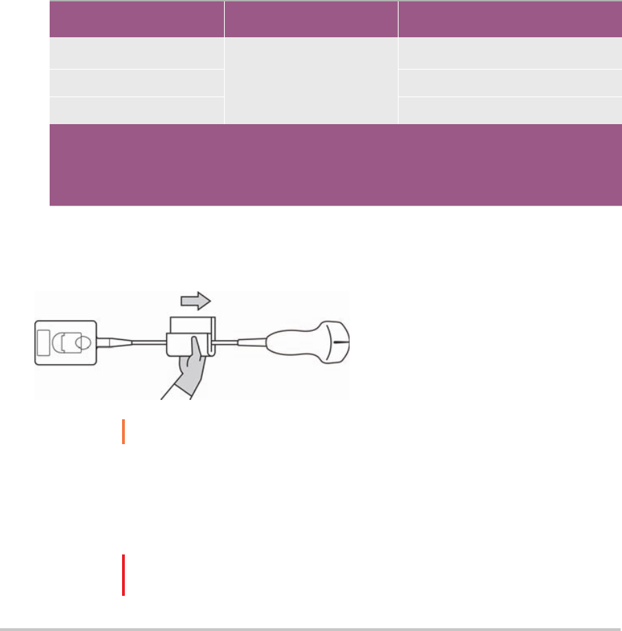
95
6 Clean the ultrasound system STAND to remove any debris or bodily fluids. For information about cleaning
the stand, see the SonoSite SII Stand User Guide.
7 Clean the TRANSDUCER CABLE AND BODY to remove any debris or bodily fluids. Use the following
procedure:
a Use either a pre-moistened wipe or a soft cloth dampened with cleaner or disinfectant. Choose a cleaner
from the list of approved cleaners.
Approved cleaners for the transducer
Product
1
Compatible Transducer
Minimum wet contact time
2
SaniCloth AF3 (gray top)
3
C11x, HFL38xi, HFL50x,
HSL25x, ICTx, L25x, L38xi,
P10x, P11x, rC60xi, rP19x
3 minutes
SaniCloth Plus (red top) 3 minutes
PI-Spray II 10 minutes
1
For a more complete list, refer to the cleaners and disinfection document available at www.sonosite.com
2
For maximum effectiveness, the component being cleaned must remain wet with disinfectant for a
minimum period of time.
3
Qualified for use as an intermediate-level disinfectant for mycobacteria.
b Remove all gel, debris, and bodily fluids from the transducer.
c With a new wipe, clean the cable and transducer, starting from the cable, wiping toward the
scanhead.This method helps to avoid cross-contamination.
Caution
Do not allow moisture near the electronic components of the connector.
d Observe the minimum wet contact time. Monitor the transducer for wet appearance. Re-apply with a
new wipe if no longer wet.
8 Verify that all gel, debris, and bodily fluids have been removed from the system and transducer. If
necessary, repeat steps 5 & 6 with a new wipe.
WARNING
Failure to remove all gel, debris, and bodily fluid could leave contaminants on the
probe.

96 Chapter 8
9 Prepare the disinfectant for use.
a Choose a high-level disinfectant from the list of approved disinfectants.
Approved disinfectants for the transducer
Disinfectant Compatible transducers Temperature
Disinfectant Soak
Duration
Cidex
C11x, HFL38xi, HFL50x, HSL25x,
ICTx, L25x, L38xi, P10x, P11x,
rC60xi, rP19x
25
o
C, 77
o
F
45 minutes
For a more complete list, refer to the cleaners and disinfection document available at www.sonosite.com.
b Check the expiration date on the bottle to ensure the disinfectant has not expired.
c Mix or check that the disinfection chemicals have the concentration recommended by the manufacturer
(for example, a chemical strip test).
d Check that the temperature of the disinfectant is within the manufacturer’s recommended limits.
10Perform a high-level disinfection of the transducer. Use the following procedure:
a Immerse the transducer in a high-level disinfectant solution for the period of time recommended by the
chemical manufacturer.
Cautions
Do not soak the transducer longer than recommended by the chemical
manufacturer.
Do not immerse the transducer connector in any disinfectant solution.
Use only FUJIFILM SonoSite recommended cleaners and disinfectants. Using a non-
recommended disinfecting solution or incorrect solution strength can damage or
discolor the transducer and void the warranty.

97
b Ensure that the connector and most of the cable remain out of the fluid. You may submerge 2 inches (5
cm) of the cable proximal to the transducer scanhead.
Do not submerge
Scan head
Cable
Connector
Maximum
5 cm
(2 inches)
Figure 8-1 Transducer component names
11 Rinse the transducer 3 separate times using the following procedure:v
WARNING
High-level disinfectants can cause harm to the patient if not completely removed
from the transducer. Follow the manufacturer’s rinse instructions to remove
chemical residue.
a Rinse the transducer in clean, running water according to the disinfectant manufacturer’s instructions
(at least 1 minute).
b Ensure that the connector and at least 12-18 inches (31-46 cm) of the cable from the connector remain
dry.
c Repeat this step until the transducer has been rinsed 3 separate times.
12 Dry with a sterile lint-free cloth.
13Dispose of the disinfectant according to the manufacturer’s guidelines.
14 Examine the transducer and cable for damage, such as cracks or splitting where fluid can enter.
If damage is evident, discontinue use of the transducer, and contact FUJIFILM SonoSite or your local
representative.

B
Option
98 Chapter 8
Clean and disinfect system and transducer to a
low level (non-critical uses)
Use the following procedure to clean and disinfect the ultrasound system and transducer if it has not come
into contact with blood, broken skin, mucosal membranes, or bodily fluids.
WARNING
If the system or transducer has come into contact with any of the following, use the
high-level cleaning and disinfection procedure. See Option A, “Clean and disinfect
system and transducer to a high level (semi-critical uses)” on page 93:
Blood
Broken skin
Mucosal membranes
Bodily fluids
Follow the manufacturer's instructions when using cleaners and disinfectants. The materials listed in the table
below are chemically compatible with the system and transducers. Confirm that the cleaners and disinfectants
are appropriate for your facility’s use..
WARNINGS
To avoid electrical shock, before cleaning, disconnect the system from the power
supply.
Wear the appropriate personal protective equipment (PPE) recommended by the
chemical manufacturer, such as eyewear and gloves.
Cautions
Do not spray cleaners or disinfectants directly on the system surfaces or on system
and transducer connectors. Doing so
may cause solution to leak into the system,
damaging it and voiding the warranty.
Use only FUJIFILM SonoSite-recommended cleaners and disinfectants. Using a non-
recommended disinfecting solution or incorrect solution strength can damage the
System and transducer and void the warranty. Follow the disinfectant
manufacturer’s recommendations for solutions strengths.
Do not attempt to disinfect a transducer or transducer cable using a method or
chemical that is not included here. Doing so can damager the transducer and void
the warranty.
To clean and disinfect the system and transducer
1
Turn off the system by pressing the Power button.
2 Unplug the power cord from the outlet.
3 Remove the transducer sheath, if applicable.

99
4 Disconnect the transducer from the system. Temporarily place it where it will not cross-contaminate clean
equipment or surfaces while you clean the ultrasound system.
5 Clean the exterior surfaces of the ULTRASOUND SYSTEM to remove any debris or bodily fluids. Use the
following procedure:
a Use either a pre-moistened wipe or a soft cloth dampened with cleaner and disinfectant. Choose a cleaner
from the list of approved cleaners.
Approved cleaners/disinfectants for the ultrasound system:
Cleaner/disinfectant
1
Minimum wet contact time
2
SaniCloth AF3 (gray top)
3
3 minutes
SaniCloth Plus (red top) 3 minutes
1
For a more complete list, refer to the cleaners and disinfection document available at www.sonosite.com
2
For maximum effectiveness, the component being cleaned must remain wet with disinfectant for a
minimum period of time.
3
Qualified for use as an intermediate-level disinfectant for mycobacteria.
b Remove all gel, debris, and bodily fluids from the system.
c With a new wipe, clean the system, including the display, by wiping from clean areas to the soiled areas.
This method helps to avoid cross-contamination.
d Observe the minimum wet contact time. Monitor the system for wet appearance. Re-apply with a new
wipe if no longer wet.
6 Clean the TRANSDUCER CABLE AND BODY to remove any debris or bodily fluids. Use the following
procedure:

100 Chapter 8
a Use either a pre-moistened wipe or a soft cloth dampened with cleaner or disinfectant. Choose a cleaner
from the list of approved cleaners.
Approved cleaners/disinfectants for the transducer:
Product Compatible Transducer
Minimum wet contact time
1
SaniCloth AF3 (gray top)
2
C11x, HFL38xi, HFL50x,
HSL25x, ICTx, L25x, L38xi,
P10x, P11x, rC60xi, rP19x
3 minutes
SaniCloth Plus (red top) 3 minutes
PI-Spray II 10 minutes
1
For maximum effectiveness, the component being cleaned must remain wet with disinfectant for a
minimum period of time.
2
Qualified for use as an intermediate-level disinfectant for mycobacteria. For a more complete list, refer to
the cleaners and disinfection document available at
www.sonosite.com
b Remove all gel, debris, and bodily fluids from the transducer.
c With a new wipe, clean the cable and transducer, starting from the cable, wiping toward the scanhead.
Caution
Do not allow moisture near the electronic components of the connector.
d Observe the required wet contact time. Monitor the transducer for wet appearance. Re-apply with a new
wipe if no longer wet.
7 Verify that all gel, debris, and bodily fluids have been removed from the system and transducer. If
necessary, repeat steps 5 and 6 with a new wipe.
8 Allow the transducer and system to air dry in a clean, well-ventilated space.
9 Examine the system, transducer and cable for damage, such as cracks or splitting where fluid can enter.
If damage is evident, do not use the transducer. Instead, contact FUJIFILM SonoSite or your local
representative.
Storing the transducer
To store the transducer
1 Make sure the transducer has been cleaned and disinfected as detailed in this chapter.
2 Store the transducer so that it hangs freely and vertically, and observe the following precautions:
Store the transducer away from any contaminated transducers.

101
Store the transducer in an environment that is safe and has good airflow. Do not store the transducer in
closed containers or where condensation may occur.
Avoid direct sunlight and exposure to x-rays. Recommended storage temperature range is between 0
o
C
(32
o
F) and +45
o
C (113
o
F).
If using a wall-mounted rack for storage, ensure that:
It is securely mounted.
The storage slots do not mar the transducer or cause damage to the cable.
The rack is sized and positioned to prevent the transducer from inadvertently falling.
Make sure the connector is supported and secure.
Transporting the transducer
When transporting the transducer, you must take precautions to protect the transducer from damage and
avoid cross-contamination. Be sure to use a container approved by your organization.
To transport a soiled transducer for cleaning
A soiled transducer is one that has been contaminated and must be cleaned before using it in an exam.
1 Place the transducer in a clean, approved container.
WARNING
To prevent cross-contamination or unprotected exposure of personnel to biological
material, containers used to transport contaminated transducers should carry an ISO
biohazard label similar to the following:
Caution
Ensure the transducer is dry before placing it in a closed container. Condensation
from a damp transducer can damage the connector.
2 Transport the transducer in the container to the point of processing. Do not open the container until the
transducer is ready to be cleaned.
Caution
Do not leave the transducer in a sealed container for long periods of time.

102 Chapter 8
To transport a clean transducer
A clean transducer is one that has completed the cleaning and disinfection process, has been stored properly,
and is ready to be used in an examination.
1 Place the transducer in a clean, approved container. To identify the transducer as clean, containers used to
transport clean transducers should carry a cleanliness verification sticker or certificate.
2 Transport the transducer in the container to the point of use. Do not open the container until the
transducer is ready to be used.
To ship a transducer
WARNING
Whenever possible, avoid shipping a contaminated transducer. Before shipping,
ensure the transducer has been cleaned and disinfected using the steps detailed in
this chapter or according to special instructions received from FUJIFILM SonoSite. If
you are returning the transducer to FUJIFILM SonoSite, document the disinfection
on a “Declaration of Cleanliness,” and attach it to the packing list.
1 Place the transducer in the shipping container and seal it. Do not allow any part of the transducer to
protrude from the container.
2 Ship the transducer using the following precautions:
Clearly label the container as fragile.
Do not stack items on top of the shipping container.
Do not exceed the shipping temperature range: -35
o
C (-31
o
F) to +65
o
C (149
o
F).
Do not open the shipping container until it reaches its final destination.
After arrival, the transducer must be cleaned and disinfected before it can be used in an exam.
Cleaning the stand
For information about cleaning the stand, see the SonoSite SII Stand User Guide.
Cleaning accessories
Clean accessories prior to disinfecting. You can disinfect the exterior surface of accessories using a
recommended disinfectant. Refer to the cleaners and disinfection document available at www.sonosite.com.
To clean and disinfect accessories
1 If necessary, unplug the power supply, and detach any cables.

103
2 Clean the exterior surfaces of the accessory using a soft cloth lightly dampened in a mild soap or detergent
cleaning solution to remove any particulate matter or body fluids.
Apply the solution to the cloth rather than the surface.
3 Mix the disinfectant solution compatible with the accessory, following disinfectant label instructions for
solution strengths and disinfectant contact duration. Refer to the cleaners and disinfection document
available at www.sonosite.com.
4 Wipe surfaces with the disinfectant solution. Follow the manufacturer’s instructions for the disinfecting
solution, including exposure time and temperature for effective disinfection.
5 Air dry or towel dry with a clean cloth.
Cleaning the ECG cable
Note ECG cables are reusable, and are non-sterile when provided.
To clean ECG cables
WARNING
Do not immerse ECG cables in any liquid.
You may clean ECG cables as many as 15 times using the following procedure:
1 Remove the cables from the system.
2 Clean the surface using a soft cloth or gauze pad lightly dampened with one of the following agents:
Green soap
Green soap tincture (US Pharmacopoeia) or alcohol free hand soap
2% glutaraldehyde solution (e.g. Cidex)
Sodium hypochlorite (10% bleach solution)
Apply the solution to the cloth rather than the surface.
3 Wipe all exposed surfaces with the dampened cloth.
4 Repeat step 2 and 3 with a clean cloth or gauze pad.
5 Dry all exposed surfaces with a clean, dry cloth or gauze pad.

104 Chapter 8
To sterilize the ECG cable
Caution
Do not use an autoclave, gamma radiation, or steam to sterilize the ECG cable.
To avoid damage, sterilize ECG cables only when necessary. Replace cables after 10 sterilization cycles.
1 Sterilize ECG cables using ethylene oxide (EtO) sterilization methods.
2 To dissipate the ethylene oxide, aerate the cables. Follow all necessary safety precautions.

105
CHAPTER 9
Safety
This chapter contains information required by regulatory agencies, including electrical and
clinical safety warnings, electromagnetic compatibility, and labeling. The information
applies to the ultrasound system, transducer, accessories, and peripherals.
Ergonomic safety
These healthy scanning guidelines are intended to assist you in the comfort and effective
use of your ultrasound system.
WARNINGS
To prevent musculoskeletal disorders, follow the guidelines in this section.
Use of an ultrasound system may be linked to musculoskeletal
disorders
a
a. Magnavita, N., L. Bevilacqua, P. Mirk, A. Fileni, and N. Castellino. “Work-related
Musculoskeletal C
omplaints in Sonologists.” Occupational Environmental Medicine. 41:11
(1999), 981-988.
,b,c
b. Craig, M. “Sonography: An Occupational Health Hazard?” Journal of Diagnostic Medical
Sonography. 3 (1985), 121-125.
.
c. Smith, C.S., G.W. Wolf, G. Y. Xie, and M. D. Smith. “Musculoskeletal Pain in Cardiac
Ultrasonographers: Results of a Random Survey.” Journal of American Society of
Echocardiography. (May1997), 357-362.
Use of an ultrasound system is defined as the physical interaction among
the operator, the ultrasound system, and the transducer.
When using an ultrasound system, as with many similar physical activities,
you may experience occasional discomfort in your hands, fingers, arms,
shoulders, eyes, back, or other parts of your body. However, if you
experience symptoms such as constant or recurring discomfort, pain,
throbbing, aching, tingling, numbness, burning sensation, or stiffness,
promptly refer to a qualified health professional. Such symptoms can be
linked with musculoskeletal disorders (MSDs). MSDs can be painful and
may result in potentially disabling injuries to the nerves, muscles, tendons,
or other parts of the body. Examples of MSDs include carpal tunnel
syndrome and tendonitis.

WARNING
While researchers are not able to definitively answer many questions about MSDs,
there is a general agreement that certain factors are associated with their
occurrence including: preexisting medical and physical conditions, overall health,
equipment and body position while doing work, frequency of work, duration of
work, and other physical activities that may facilitate the onset of MSDs
a
a. Wihlidal, L.M. and S. Kumar. “An Injury Profile of Practicing Diagnostic Medical Sonographers in Alberta.”
International Journal of Industrial Er
gonomics. 19 (1997), 205-216.
. This
section provides guidelines that may help you work more comfortably and may
reduce your risk of MSDs
b
b. Habes, D.J. and S. Baron. “Health Hazard Report 99-0093-2749.” Univ
ersity of Medicine and Dentistry of
New Jersey. (1999).
,c
.
c. Vanderpool, H.E., E.A. Friis, B.S. Smith, and K.L. Harms. “Prevalence of Carpal Tunnel Syndrome and Other
Work-related Musculoskeletal Problems in Cardiac Sonographers.” Journal of Medicine. 35:6 (1993), 605-
610.
106 Chapter 9
Position the system
Promote comfortable shoulder, arm, and hand postures
Use a stand to support the weight of the ultrasound system.
Minimize eye and neck strain
If possible, position the system within reach.
Adjust the angle of the system and display to minimize glare.
If using a stand, adjust its height so that the display is at or slightly below eye level.
Position yourself
Support your back during an exam
Use a chair that supports your lower back, that adjusts to your work surface height, that promotes a natural
body posture, and that allows for quick height adjustments.
Sit or stand upright. Avoid bending or stooping.
Minimize reaching and twisting
Use a bed that is height adjustable.
Position the patient as close to you as possible.
Face forward. Avoid twisting your head or body.
Move your entire body front to back, and position your scanning arm next to or slightly in front of you.
Stand for difficult exams to minimize reaching.
Position the ultrasound system directly in front of you.
Promote comfortable shoulder and arm postures
Keep your elbow close to your side.

107
Relax your shoulders in a level position.
Support your arm using a support cushion or pillow, or rest it on the bed.
Promote comfortable hand, wrist, and finger postures
Hold the transducer lightly in your fingers.
Minimize the pressure applied on the patient.
Keep your wrist in a straight position.
Take breaks, exercise, and vary activities
Minimizing scanning time and taking breaks can effectively allow your body to recover from physical
activity and help you avoid MSDs. Some ultrasound tasks may require longer or more frequent breaks.
However, simply changing tasks can help some muscle groups relax while others remain or become active.
Work efficiently by using the software and hardware features correctly.
Keep moving. Avoid sustaining the same posture by varying your head, neck, body, arm, and leg positions.
Targeted exercises can strengthen muscle groups, which may help you avoid MSDs. Contact a qualified
health pr
ofessional to determine stretches and exercises that are right for you.
Electrical safety classification
Class I equipment
The ultrasound system is classified as Class I equipment when
powered from the external power supply or mounted on the
stand because the external power supply is a Class 1 protectively
earthed power supply. The stand has no protective earth. Ground
bond testing is not applicable to the ultrasound system or the
stand.
Note: AC powered peripherals that may be used with the system are
Class I and are individually protectively earthed. Ground bond testing
may be conducted on each AC powered peripheral.
Internally powered equipment
Ultrasound system not connected to the power supply (battery
only)
Type BF applied parts Ultrasound transducers
IPX-7 (watertight equipment) Ultrasound transducers
Non AP/APG
Ultrasound system power supply, SonoSite SII stand, and
peripherals. Equipment is not suitable for use in the presence of
flammable anaesthetics.

108 Chapter 9
Electrical safety
This system meets EN60601-1, Class I/internally-powered equipment requirements and Type BF isolated
patient-applied parts safety requirements.
The system complies with the standards as listed in the Standards section of this document. Refer to
“Standards” on page 127
For maximum safety observe the following warnings and cautions.
WARNINGS
To avoid discomfort or minor risk of patient injury, keep hot surfaces away from the
patient.
To avoid the risk of injury, do not operate the system in the presence of flammable
gasses or anesthetics. Explosion can result.
To avoid the risk of electrical shock or injury, do not open the system enclosures. All
internal adjustments and replacements, except battery replacement, must be made
by a qualified technician.
WARNINGS
To avoid the risk of electrical shock:
Do not allow any part of the system (including the bar code scanner, external
mouse, power supply, power supply connector, external keyboard, and so on),
except for the transducer, to touch the patient.
Use only properly grounded equipment. Shock hazards exist if the power supply is
not properly grounded. Grounding reliability can only be achieved when
equipment is connected to a receptacle marked “Hospital Only” or “Hospital
Grade” or the equivalent. The grounding wire must not be removed or defeated.
When using the system in an environment where the integrity of the protective
earth conductor arrangement is in doubt, operate the system on battery power
only, without using the power supply.
Do not touch any of the following:
The signal input/output connectors on the back of the ultrasound system
The system battery contacts (inside the battery compartment)
The system transducer connectors when the transducers are disconnected
Do not connect either of the following to an MSO or extension cord:
System power supply
Auxiliary mains outlet receptacles on the SonoSite SII stand

109
Equipment safety
To protect your ultrasound system, transducer, and accessories, follow these precautions.
Cautions
Excessive bending or twisting of cables can cause a failure or intermittent
operation.
Improper cleaning or disinfecting of any part of the system can cause permanent
damage. For cleaning and disinfecting instructions, refer to “Troubleshooting and
Maintenance” on page 87
Do not submerge the transducer connector in solution. The cable is not liquid-tight
beyond the transducer connector/cable interface.
Do not use solvents such as thinner or benzene, or abrasive cleaners on any part of
the system.
Remove the battery from the system if the system is not likely to be used for some
time.
Do not spill liquid on the system.
WARNINGS
Before using the transducer, inspect the transducer face, housing, and cable. Do not
use the transducer if the transducer or cable is damaged.
Always disconnect the power supply from the system before cleaning the system.
Do not use any transducer that has been immersed beyond the specified cleaning
or disinf
ection level. Refer to “Troubleshooting and Maintenance” on page 87
Use only accessories and peripherals recommended by FUJIFILM SonoSite,
including the po
wer supply. Connection of accessories and peripherals not
recommended by FUJIFILM SonoSite could result in electrical shock. Contact
FUJIFILM SonoSite or your local representative for a list of accessories and
peripherals available from or recommend by FUJIFILM SonoSite.
WARNINGS
To avoid the risk of electrical shock and fire hazard:
Inspect the power supply, AC power cords, cables, and plugs on a regular basis.
Ensur
e that they are not damaged.
The power cord set that connects the power supply of the ultrasound system,
SonoSite SII stand to mains power must only be used with the power supply or
stand, and cannot be used to connect other devices to mains power.
WARNING
To prevent injury to the operator/bystander, the transducer must be removed from
patient contact before the application of a high-voltage defibrillation pulse.
Cautions
Do not use the system if an error message appears on the image display: note the
error code; call FUJIFILM SonoSite or your local representative; turn off the system
by pressing and holding the power key until the system powers down.
To avoid increasing the system and transducer connector temperature, do not
block the airflow to the ventilation holes.

110 Chapter 9
Battery safety
To prevent the battery from bursting, igniting, or emitting fumes and causing personal injury or equipment
damage, observe the following precautions.
WARNING
The battery has a safety device. Do not disassemble or alter the battery.
Charge the batteries only when the ambient temperature is between 0° and 40°C
(32° and 104°F).
Do not short-circuit the battery by directly connecting the positive and negative
t
erminals with metal objects.
Do not touch battery contacts.
Do not heat the battery or discard it in a fire.
Do not expose the battery to temperatures over 60°C (140°F). Keep it away from fire
and other heat sources.
Do not charge the battery near a heat source, such as a fire or heater.
Do not leave the battery in direct sunlight.
Do not pierce the battery with a sharp object, hit it, or step on it.
Do not use a damaged battery.
Do not solder a battery.
The polarity of the battery terminals are fixed and cannot be switched or reversed.
Do not force the battery into the system.
Do not connect the battery to an electrical power outlet.
Do not continue recharging the battery if it does not recharge after two successive
six hour charging cycles.
Do not ship a damaged battery without instructions from FUJIFILM SonoSite
Technical Support. Refer to “Getting help” on page 2.
If the battery leaks or emits an odor, remove it from all possible flammable sources.
Periodically, check to make sure that the battery charges fully. If the battery fails to
charge fully, replace it.
Cautions
Do not immerse the battery in water or allow it to get wet.
Do not put the battery into a microwave oven or pressurized container.
If the battery emits an odor or heat, is deformed or discolored, or in any way appears
abnormal during use, recharging or storage, immediately remove it and stop using
it. If you have any questions about the battery, consult FUJIFILM SonoSite or your
local representative.
Use only FUJIFILM SonoSite batteries.
Do not use or charge the battery with non-FUJIFILM SonoSite equipment. Only
charge the battery with the system.

111
Clinical safety
WARNINGS
Non-medical (commercial) grade peripheral monitors have not been verified or
validated by FUJIFILM SonoSite as being suitable for diagnosis.
Do not use the system if it exhibits erratic or inconsistent behavior. Discontinuities
in the scanning sequenc
e are indicative of a hardware failure that must be
corrected before use.
Some transducer sheaths contain natural rubber latex and talc, which can cause
allergic reactions in some individuals. Refer to 21 CFR 801.437, User labeling for
devices that contain natural rubber.
Perform ultrasound procedures prudently. Use the ALARA (as low as reasonably
achievable) principle and f
ollow the prudent use information concerning MI and TI.
FUJIFILM SonoSite does not currently recommend a specific brand of acoustic
standoff
. If an acoustic standoff is used, it must have a minimum attentuation
of .3dB/cm/MHz.
Electromagnetic compatibility
The ultrasound system has been tested and found to comply with the electromagnetic compatibility (EMC)
limits for medical devices to IEC 60601-1-2:2001. These limits are designed to provide reasonable protection
against harmful interference in a typical medical installation.
WARNING
To avoid the risk of increased electromagnetic emissions or decreased immunity,
use only accessories and peripherals recommended by FUJIFILM SonoSite.
Connection of accessories and peripherals not recommended by FUJIFILM SonoSite
could result in malfunctioning of your ultrasound system or other medical electrical
devices in the area. Contact FUJIFILM SonoSite or your local representative for a list
of accessories and peripherals available from or recommended by FUJIFILM
SonoSite. See “Compatible accessories and peripherals” on page 114.

112 Chapter 9
Wireless transmission
The SonoSite Edge II ultrasound system contains an IEEE 802.11 transmitter that utilizes the ISM frequency
bands from 2.412 to 2.484GHz and implements two methods of transmission:
IEEE 802.11b with Complimentary Code Keying (CCK), Differential Quarternary Phase Shift Keying (DQPSK),
and Differential Binary Phase Shift Keying (DBPSK) at 16 dB
IEEE 802.11g with Orthogonal Frequency Division Multiplexing (ODFM) at 13 dBm
Cautions
Medical electrical equipment requires special precautions regarding EMC and
must be installed and operated according to these instructions. Portable and
mobile RF communications equipment can affect the ultrasound system.
Electromagnetic interference (EMI) from other equipment or interference sources
could result in performance disruption of the ultrasound system. Evidence of
disruption may include image degradation or distortion, erratic readings,
equipment ceasing to operate, or other incorrect functioning. If this occurs, survey
the site to determine the source of disruption, and take the following actions to
eliminate the source(s).
Turn equipment in the vicinity off and on to isolate disruptive equipment.
Relocate or re-orient interfering equipment.
Increase distance between interfering equipment and your ultrasound system.
Manage use of frequencies close to ultrasound system frequencies.
Remove devices that are highly susceptible to EMI.
Lower power from internal sources within facility control (such as paging
systems).
Label devices susceptible to EMI.
Educate clinical staff to recognize potential EMI-related problems.
Eliminate or reduce EMI with technical solutions (such as shielding).
Restrict use of personal communicators (cell phones, computers) in areas with
devices susceptible to EMI.
Share relevant EMI information with others, particularly when evaluating new
equipment purchases which may generate EMI.
Purchase medical devices that comply with IEC 60601-1-2 EMC Standards.
Do not stack other equipment on the ultrasound system or use other equipment
in close proximity and adjacent to the ultrasound system. If stacking or using other
equipment in close proximity is unavoidable, then you must observe the system to
verify normal operation.

113
Electrostatic discharge
Caution
Electrostatic discharge (ESD), or static shock, is a naturally occurring
phenomenon. ESD is common in conditions of low humidity, which can be
caused by heating or air conditioning. ESD is a discharge of the electrical energy
from a charged body to a lesser or non-charged body. The degree of discharge
can be significant enough to cause damage to a transducer or an ultrasound
system. The following precautions can help reduce ESD: anti-static spray on
carpets, anti-static spray on linoleum, and anti-static mats.
WARNINGS
Unless following ESD precautionary procedures, do not connect to or touch (with
body or hand-held tools) pins (contacts) of connectors that have the ESD
Sensitive Devices label:
Electrostatic Sensitive
Pins (contacts)
Pins (contacts)
Devices Label
on the system
on transducer
Figure 9-1 The transducer connector is an example of an electrostatically-
sensitive device.
If the symbol is on a border surrounding multiple connectors, the symbol pertains
to all connectors within the border.
ESD precautionary procedures include the following:
All staff involved must receive training about ESD, including the following at a
minimum: an explanation of the ESD warning symbol, ESD precautionary
procedures, an introduction to the physics of electrostatic charge, the voltage
levels that can occur in normal practice, and the damage that can occur to
electronic components if equipment is touched by an individual who is
electrostatically charged (IEC 60601-1-2, section 5.2.1.2 d).
Prevent the buildup of electrostatic charge. For example, use humidification,
conductive floor coverings, nonsynthetic clothing, ionizers, and minimizing
insulating materials.
Discharge your body to earth.
Use a wrist strap to bond yourself to the ultrasound system or to earth.
Separation distance
The SonoSite SII ultrasound system is intended for use in an electromagnetic environment in which radiated

114 Chapter 9
radio frequency (RF) disturbances are controlled. The customer or the user of the SonoSite SII ultrasound
system can help prevent electromagnetic interference by maintaining a minimum distance between portable
and mobile RF communications equipment (transmitters) and the SonoSite SII ultrasound system as
recommended below, according to the maximum output power of the communications equipment.
Table 9-1: Recommended separation between portable and mobile RF communications equipment
and the SonoSite Edge II ultrasound system
Rated maximum out-
put power of trans-
mitter
Watts
Separation distance according to frequency of transmitter m
150 kHz to 80 MHz
d=1.2 √P
80 MHz to 800 MHz
d=1.2 √P
800 MHz to 2.5 GHz
d=2.3 √P
0.01 0.12 0.12 0.23
0.1 0.38 0.38 0.73
1 1.2 1.2 2.3
10 3.8 3.8 7.3
100 12 12 23
For transmitters rated at a maximum output power not listed above, the recommended separation distance
(d) in meters (m) can be estimated using the equation applicable to the frequency of the transmitter, where
P is the maximum output power rating of the transmitter in watts (W) according to the transmitter
manufacturer.
Notes
At 80 MHz and 800 MHz, the separation distance for the higher frequency
range applies.
These guidelines may not apply in all situations. Electromagnetic propagation
is affected by absorption and reflection from structures, objects, and people.
Compatible accessories and peripherals
FUJIFILM SonoSite has tested the SonoSite SII Ultrasound System with the following accessories and
peripherals and has demonstrated compliance to the requirements of IEC60601-1-2:2007.
You may use these FUJIFILM SonoSite accessories and third-party peripherals with the SonoSite SII ultrasound
system.
WARNINGS
Use of the accessories with medical systems other than the SonoSite SII
ultrasound system may result in increased emissions or decreased immunity of
Use of accessories other than those specified may result in increased emissions or
decreased immunity of the ultrasound system.

115
Table 9-2: Accessories and peripherals compatible with SonoSite SII ultrasound system
Description Maximum Cable Length
C11x transducer 6.0 ft/1.8 m
rC60xi transducer standard/armored 5.5 ft/1.7 m
HFL38xi transducer 5.5 ft/1.7 m
HFL50x transducer 5.7 ft/1.7 m
HSL25x transducer 8.0 ft/2.4 m
ICTx transducer 5.5 ft/1.7 m
L25x transducer 7.5 ft/2.3 m
L38xi transducer standard/armored 5.5 ft/1.7 m
L52x transducer 7.9 ft/2.4 m
P10x transducer 6.0 ft/1.8 m
P11x transducer 6.5 ft/2.0 m
rP19x transducer standard/armored 6.0 ft/1.8 m
Bar code scanner 4.8 ft/1.5 m
Battery for PowerPack —
Battery Pack —
Battery PowerPack —
Black & white printer —
Black & white printer power cable 3.3 ft/1 m
Black & white printer control cable 5.9 ft/1.8 m
Black & white printer video cable 6.2 ft/1.9 m
SonoSite SII Stand —
Power cord (system) 10 ft/3 m
Power supply with DC cable 6.8 ft/2 m
Power supply AC cable 39 in/1 m
PowerPark —

116 Chapter 9
Manufacturer’s declaration
The tables in this section document the intended use environment and EMC compliance levels of the system.
For maximum performance, ensure that the system is used in the environments described in this table.
The system is intended for use in the electromagnetic environment specified below.
Table 9-3: Manufacturer’s Declaration - Electromagnetic Emissions
Emissions Test Compliance Electromagnetic Environment
RF emissions
ClSPR 11
Group 1 The SonoSite SII ultrasound system
uses RF energy only for its internal
function. Therefore, its RF emissions
are very low and are not likely to
cause any interference in nearby
electronic equipment.
RF emissions
ClSPR 11
Class A
The SonoSite SII ultrasound system
is suitable for use in all
establishments other than domestic
and those directly connected to the
public low-voltage power supply
network which supplies buildings
used for domestic purposes.
Harmonic emissions
IEC 61000-3-2
Class A
Voltage fluctuations/flicker
emissions
IEC 61000-3-3
Complies
USB wireless adapter —
USB memory drive —
For transducers, the maximum cable length is measured between the strain reliefs. The stated length do not include
the lengths of cable in the following locations: underneath the strain reliefs, inside the transducer enclosure, and
inside the transducer connector.
Table 9-2: Accessories and peripherals compatible with SonoSite SII ultrasound system (Continued)
Description Maximum Cable Length

117
The system is intended for use in the electromagnetic environment specified below.
Table 9-4: Manufacturer’s Declaration - Electromagnetic Immunity
Immunity Test IEC 60601 Test Level Compliance Level
Electromagnetic Environment
Electrostatic
Discharge (ESD)
IEC 61000-4-2
± 2.0KV, ± 4.0KV, ±
6.0KV contact
± 2.0KV, ± 4.0KV, ±
8.0KV air
± 2.0KV, ± 4.0KV, ±
6.0KV contact
± 2.0KV, ± 4.0KV, ±
8.0KV air
Floors should be wood, concrete or
ceramic tile. If floors are covered with
synthetic material, the relative humidity
should be at least 30%.
Electrical fast
Transient burst
IEC 61000-4-4
± 2KV on the mains
± 1KV on signal lines
± 2KV on the
mains
± 1KV on signal
lines
Mains power quality should be that of a
typical commercial or hospital
environment.
Surge
IEC 61000-4-5
± 1KV line(s) to line(s)
± 2KV line(s) to earth
± 1KV line(s) to
line(s)
± 2KV line(s) to
earth
Mains power quality should be that of a
typical commercial or hospital
environment.
Voltage dips,
short
interruptions
and voltage
variations on
power supply
input lines
IEC 61000-4-11
<5% U
T
(>95% dip in U
T
) for
0.5 cycle
40% U
T
(60% dip in U
T
) for 5
cycles
70% U
T
(30% dip in U
T
) for 25
cycles
<5% U
T
(>95% dip in U
T
) for
5s
<5% U
T
(>95% dip in U
T
)
for 0.5 cycle
40% U
T
(60% dip in U
T
) for
5 cycles
70% U
T
(30% dip in
U
T
) for 25 cycles
<5% U
T
(>95% dip in U
T
)
for 5s
Mains power quality should be that of a
typical commercial or hospital
environment. If the user of the FUJIFILM
SonoSite ultrasound system requires
continued operation during power
mains interruptions, it is recommended
that the FUJIFILM SonoSite ultrasound
system be powered from an
uninterruptible power supply or a
battery.
Power
Frequency
Magnetic Field
IEC 61000-4-8
3 A/m 3 A/m If image distortion occurs, it may be
necessary to position the FUJIFILM
SonoSite ultrasound system further
from sources of power frequency
magnetic fields or to install magnetic
shielding. The power frequency
magnetic field should be measured in
the Intended installation location to
assure that it is sufficiently low.

118 Chapter 9
FCC Caution: Changes or modifications not expressly approved by the party responsible for compliance could
void the user’s authority to operate the equipment.
This device complies with part 15 of the FCC Rules. Operation is subject to the following two conditions:
Conducted RF
IEC 61000-4-6
3 Vrms
150 kHz to 80 MHz
3 Vrms Portable and mobile RF
communications equipment should be
used no closer to any part of the
FUJIFILM SonoSite ultrasound system
including cables, than the
recommended separation distance
calculated from the equation applicable
to the frequency of the transmitter.
Recommended Separation Distance
d = 1.2 √P
Radiated RF
IEC 61000-4-3
3 V/m
80 MHz to 2.5 GHz
3 V/m Field strengths from fixed RF
transmitters, as determined by an
electromagnetic site survey
a
, should be
less than the compliance level in each
frequency range
b
.
Interference may occur in the vicinity of
equipment marked with the following
symbol:
(IEC 60417 No. 417-IEC-5140: “Source of
non-ionizing radiation”)
Note U
T
is the AC mains voltage prior to application of the test level.
At 80 MHz and 800 MHz, the higher frequency range applies.
These guidelines may not apply in all situations. Electromagnetic propagation is
affected by absorption and reflection from structures, objects and people.
a. Field strengths from fixed transmitters such as base stations for radio (cellular/cordless) telephones and land
mobile radios, amateur radio, AM and FM radio broadcast and TV broadcast cannot be predicted theoretically with
accuracy. To assess the electromagnetic environment due to fixed RF transmitters, an electromagnetic site survey
should be considered. If the measured field strength in the location in which the FUJIFILM SonoSite ultrasound
system is used exceeds the applicable RF compliance level above, the FUJIFILM SonoSite ultrasound system should
be observed to verify normal operation. If abnormal performance is observed, additional measures may be
necessary, such as re-orienting or relocating the FUJIFILM SonoSite ultrasound system.
b. Over the frequency range 150 kHz to 80 MHz, field strengths should be less than 3 V/m.
Table 9-4: Manufacturer’s Declaration - Electromagnetic Immunity
Immunity Test IEC 60601 Test Level Compliance Level
Electromagnetic Environment

119
This device may not cause harmful interference.
This device must accept any interference received, including interference that may cause undesired
operation.
This device complies with part 15 of the FCC Rules. Operation is subject to the following two conditions:
This device may not cause harmful interference.
This device must accept any interference received, including interference that may cause undesired
operation.
Immunity testing requirements
The SonoSite SII ultrasound system complies with the essential performance requirements specified in IEC
60601-1-2 and IEC 60601-2-37. Results of immunity testing show that the SonoSite SII ultrasound system
meets these requirements and is free from the following:
Noise on a waveform or artifacts or distortion in an image or error of a displayed numerical value that
cannot be attributed to a physiological effect and that may alter the diagnosis
Display of incorrect numerical values associated with the diagnosis to be performed
Display of incorrect safety related indications
Production of unintended or excessive ultrasound output
Production of unintended or excessive transducer assembly surface temperature
Production of unintended or uncontrolled motion of transducer assemblies intended for intra-corporeal
use
Labeling symbols
The following symbols are used on the products, packaging, and containers.
Symbol Definition
Follow instructions for use.
Manufacturer, or Manufacturer and date of manufacture
Authorized representative in the European Community
Alternating Current (AC)

120 Chapter 9
Class 1 device indicating manufacturer’s declaration of conformance with
Annex VII of 93/42/EEC
Class 1 device requiring verification by the Notified Body of sterilization or
measurement features, or to a Class IIa, IIb, or III device requiring verification or
auditing by the Notified Body to applicable Annex(es) of 93/42/EEC
Attention, refer to the user guide
Device complies with relevant Australian regulations for electronic devices.
LOT
Batch code, date code, or lot code type of control number
Biological risk
Canadian Standards Association. The “C” and “US” indicators next to this mark
signify that the product has been evaluated to the applicable CSA and ANSI/UL
Standards, for use in Canada and the US, respectively.
REF
Catalog number
Collect separately from other household waste (refer to European Commission
Directive 93/86/EEC). Refer to local regulations for disposal.
STERILE EO
Contents sterilized using ethylene oxide process.
Corrugated recycle
Dangerous voltage
Symbol Definition

121
Date of manufacture
Direct Current (DC)
Do not get wet.
Do not stack over 2 high.
Do not stack over 5 high.
Do not stack over 10 high.
Electrostatic sensitive devices
Device complies with relevant FCC regulations for electronic devices.
Fragile
GEL Gel
STERILE R
Sterilized using irradiation.
Hot
Symbol Definition
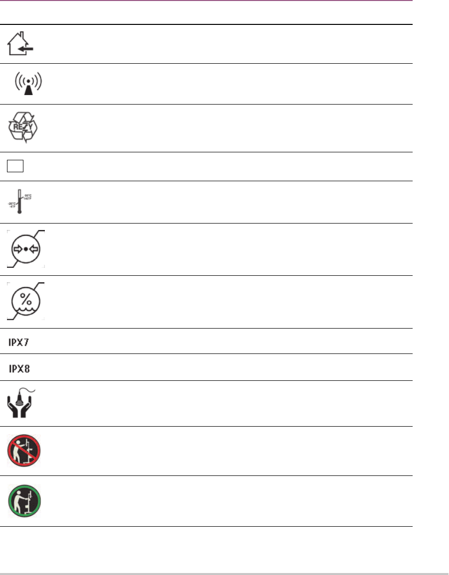
122 Chapter 9
Indoor use only
Non-ionizing radiation
Paper recycle
SN
Serial number type of control number
Temperature limitation
Atmospheric pressure limitation
Humidity limitations
Submersible. Protected against the effects of temporary immersion.
Water-Tight Equipment. Protected against the effects of extended immersion.
Handle transducer with care.
To avoid tipping, do not move the system using the handle on the front of the
SonoSite SII ultrasound system.
When moving the system, push the stand using the tray assembly.
Symbol Definition

123
Specifications
This chapter contains system and accessory specifications and standards. The specifications for recommended
peripherals are in the manufacturers’ instructions.
System
Dimensions
Height: 44.7 cm (17.6 inches)
Height with stand:
Max: 151 cm (59.5 inches)
Min:124.5 cm (49 inches)
Type BF patient applied part
(B = body, F = floating applied part)
A mandatory action that the user shall read the accompanying documentation
for more information.
Pollution Control Logo. (Applies to all parts/products listed in the China RoHS
disclosure table. May not appear on the exterior of some parts/products
because of space limitations.)
China Compulsory Certificate mark (“CCC Mark”). A compulsory safety mark for
compliance to Chinese national standards for many products sold in the
People’s Republic of China.
Maximum weight load
WARNING:
Connect Only
Accessories and
Peripherals
Recommended
by FUJIFILM
SonoSite
WARNING: Connect Only
Accessories and Peripherals
Recommended by FUJIFILM SonoSite
Symbol Definition

124 Chapter 9
Width: 28.7 cm (11.3 inches)
Depth: 12.2 cm (4.8 inches)
Weight
System: 5.7 kg (12.5 lbs)
System with stand: 26.1 kg (57.5 lbs.)
Supported transducers
Table 9-5: Supported transducers
Description Maximum Cable Length
C11x transducer 6.0 ft/1.8 m
rC60xi transducer standard/armored 5.5 ft/1.7 m
HFL38xi transducer 5.5 ft/1.7 m
HFL50x transducer 5.7 ft/1.7 m
HSL25x transducer 8.0 ft/2.4 m
ICTx transducer 5.5 ft/1.7 m
L25x transducer 7.5 ft/2.3 m
L38xi transducer standard/armored 5.5 ft/1.7 m
L52x transducer 7.9 ft/2.4 m
P10x transducer 6.0 ft/1.8 m
P11x transducer 6.5 ft/2.0 m
rP19x transducer standard/armored 6.0 ft/1.8 m
For transducers, the maximum cable length is measured between the strain reliefs. The stated length does not include
the lengths of cable in the following locations: underneath the strain reliefs, inside the transducer enclosure, and
inside the transducer connector.
Imaging modes
2D (256 gray shades)
Color power Doppler (CPD) (256 colors)
Color Doppler (Color) (256 colors)
M Mode
Tissue Harmonic Imaging (THI)

125
Images and clips storage
Internal storage: The number of images and clips you can save depends on imaging mode and file format.
Accessories
The following items are either included with or available for use on the ultrasound system.
Battery
Biopsy Guide
Education keys
Mobile docking system
Needle Guide
Power supply
PDAS Image Manager
System AC power cord (10 ft/3.1 m)
SonoRemote control
Peripherals
Peripherals include medical grade (conforming to EN60601-1 requirements) and non-medical grade
(commercial) products. Manufacturer’s instructions accompany each peripheral.
Medical grade
Bar code scanner, serial
Bar code scanner, USB
Black-and-white printer
Recommended sources for printer paper:
To order supplies or to find the local distributor, contact Sony at www.sony.com/digitalphotofinishing.
DVD recorder
Non-medical grade
Kensington Security Cable
USB keyboard
Environmental limits
Note
The temperature, pressure, and humidity limits apply ony to the ultrasound system,
transducers and battery.
Operating (system, battery and transducer)
10–40°C (50–104°F), 15–95% R.H.

126 Chapter 9
700 to 1060hPa(0.7 to 1.05 ATM)
Shipping and storage (system and transducer)
-35–65°C (-31–149°F), 15–95% R.H.
500 to 1060hPa (0.5 to 1.05 ATM)
Shipping and storage (battery )
-20 – 60°C (-4 –140°F), 15 – 95% R.H. (For storage longer than 30 days, store at or below room temperature.)
500 – 1060hPa (0.5 – 1.05 ATM)
Electrical specifications
Power Supply Input: 100 – 240 VAC, 50/60 Hz,
2.0 – 1.0 A
Power Supply Output #1: 15.0 VDC, 5.0 A maximum
Power Supply Output #2: 9-12.6 VDC, 2.3 A maximum
Note Combined output not exceeding 75 watts.
Battery specifications
The battery comprises six lithium-ion cells plus electronics, a temperature sensor, and battery contacts. Run
time is up to two hours, depending on imaging mode and display brightness.

127
Standards
Electromechanical safety standards
Table 9-6: Electromechanical safety standards
Standard Description
ANSI/AAMI ES60601-
1:2005/(R) 2012, and
A1:2012
Medical electrical equipment, Part 1: General requirements for basic safety
and essential performance (Consolidated Edition 3.1)
CAN/CSA C22.2 No. 60601-
1:2014 (Edition 3.1)
Medical electrical equipment - Part 1: General Requirements for Basic Safety
and Essential Performance
IEC 60601-1:2012 (Edition
3.1)
Medical electrical equipment - Part 1: General Requirements for Basic Safety
and Essential Performance
IEC 60601-2-37:2007 Medical Electrical Equipment – Part 2-37: Particular requirements for the
basic safety and essential performance of ultrasonic medical diagnostic and
monitoring equipment
IEC 60601-1-6:2010 Medical Electrical Equipment part 1-6: General requirements for basic safety
and essential performance – Collateral Standard: Usability
JIS T0601-1:2013 (3rd
Edition)
Japanese Industrial Standard, General Requirements for Safety of Medical
Electrical Equipment
EMC standards classification
Table 9-7: EMC standards classification
Standard Description
IEC 60601-1-2:2007 Medical Electrical Equipment. General Requirements for Basic Safety and
Essential Performance-Collateral Standard. Electromagnetic Compatibility.
Requirements and Tests.
CISPR 11:2009 Industrial, Scientific, and Medical (ISM) Radio-Frequency Equipment
Electromagnetic Disturbance Characteristics-Limits and Methods of
Measurement.
The Classification for the ultrasound system, stand, accessories, and peripherals when configured together is:
Group 1, Class A.

128 Chapter 9
Biocompatibility standards
AAMI/ANSI/ISO 10993-1:2009, Biological evaluation of medical devices—Part 1: Evaluation and testing (2009).
AAMI/ANSI/ISO 10993-5, Biological evaluation of medical devices—Part 5: Tests for In Vitro cytotoxicity (2009).
AAMI/ANSI/ISO 10993-10, Biological evaluation of medical devices—Part 10: Tests for irritation and delayed-
type hypersensitivity (2014).
AAMI/ANSI/ISO 10993-11, Biological evaluation of medical devices—Part 11: Tests for systemic toxicity (2006).
AAMI/ANSI/ISO 10993-12, Biological evaluation of medical devices—Part 12: Sample preparation and
reference materials (2012).
Airborne equipment standards
RTCA DO-160E, Radio Technical Commission for Aeronautics, Environmental Conditions and Test Procedures
for Airborne Equipment, Section 21.0 Emission of Radio Frequency Energy, Category B. 118.
DICOM standard
The system conforms to the DICOM standard as specified in the SonoSite Edge II, SonoSite SII DICOM
Conformance Statement, available at www.sonosite.com. This statement provides information about the
purpose, characteristics, configuration, and specifications of the network connections supported by the
system.
HIPAA standard
The system includes security settings that help you to meet the applicable security requirements listed in the
HIPAA standard. Users are ultimately responsible for ensuring the security and protection of all electronic
protected health information collected, stored, reviewed, and transmitted on the system.
The Health Insurance Portability and Accountability Act, Pub.L. No. 104-191 (1996). 45 CFR 160, General
Administrative Requirements.
45 CFR 164, Security and Privacy.

129
CHAPTER 10
Acoustic Output
This chapter contains information required by regulatory agencies, including information
about the ALARA (as low as reasonably achievable) principle, the output display standard,
acoustic power and intensity tables, and other safety information. The information applies
to the ultrasound system, transducer, accessories, and peripherals.
ALARA principle
ALARA is the guiding principle for the use of diagnostic ultrasound. Sonographers and other
qualified ultrasound users, using good judgment and insight, determine the exposure that
is “as low as reasonably achievable.” There are no set rules to determine the correct exposure
for every situation. The qualified ultrasound user determines the most appropriate way to
keep exposure low and bioeffects to a minimum, while obtaining a diagnostic examination.
A thorough knowledge of the imaging modes, transducer capability, system setup and
scanning technique is necessary. The imaging mode determines the nature of the
ultrasound beam. A stationary beam results in a more concentrated exposure than a
scanned beam, which spreads that exposure over that area. The transducer capability
depends upon the frequency, penetration, resolution, and field of view. The default system
presets are reset at the start of each new patient. It is the scanning technique of the qualified
ultrasound user along with patient variability that determines the system settings
throughout the exam.
The variables that affect the way the qualified ultrasound user implements the ALARA
principle include patient body size, location of the bone relative to the focal point,
attenuation in the body, and ultrasound exposure time. Exposure time is an especially useful
variable, because the qualified ultrasound user can control it. The ability to limit the
exposure over time supports the ALARA principle.
Applying the ALARA principle
The system imaging mode selected by the qualified ultrasound user is determined by the
diagnostic information required. 2D imaging provides anatomical information; CPD imaging
provides information about the energy or amplitude strength of the Doppler signal over
time at a given anatomical location and is used for detecting the presence of blood flow;
Color imaging provides information about the energy or amplitude strength of the Doppler
signal over time at a given anatomical location and is used for detecting the presence,

130 Chapter 10
velocity, and direction of blood flow; Tissue Harmonic Imaging (THI) uses higher received frequencies to
reduce clutter, artifact, and improve resolution on the 2D image. Understanding the nature of the imaging
mode used allows the qualified ultrasound user to apply the ALARA principle.
Prudent use of ultrasound requires that patient exposure to ultrasound be limited to the lowest ultrasound
output for the shortest time necessary to achieve acceptable diagnostic results. Decisions that support
prudent use are based on the type of patient, exam type, patient history, ease or difficulty of obtaining
diagnostically useful information, and potential localized heating of the patient due to transducer surface
temperature.
The system has been designed to ensure that temperature at the face of the transducer will not exceed the
limits established in Section 42 of EN 60601-2-37: Particular requirement for the safety of ultrasound medical
diagnostic and monitoring equipment. See “Transducer surface temperature rise” on page 136. In the
event of a device malfunction, there are redundant controls that limit transducer power. This is accomplished
by an electrical design that limits both power supply current and voltage to the transducer.
The sonographer uses the system controls to adjust image quality and limit ultrasound output. The system
controls are divided into three categories relative to output: controls that directly affect output, controls that
indirectly affect output, and receiver controls.
Direct controls
The system does not exceed a spatial peak temporal average intensity (ISPTA) of 720 mW/cm
2
for all imaging
modes. (For either the Ophthalmic or Orbital exam, the acoustic output is limited to the following values: ISPTA
does not exceed 50 mW/cm
2
; TI does not exceed 1.0, and MI does not exceed 0.23.) The mechanical index (MI)
and thermal index (TI) may exceed values greater than 1.0 on some transducers in some imaging modes. One
may monitor the MI and TI values and adjust the controls to reduce these values. See “Guidelines for
reducing MI and TI” on page 131. Additionally, one means for meeting the ALARA principle is to set the MI or
TI values to a low index value and then modifying this level until a satisfactory image or Doppler mode is
obtained. For more information on MI and TI, refer to BS EN 60601-2-37:2001: Annex HH.
Indirect controls
The controls that indirectly affect output are controls affecting imaging mode, freeze, and depth. The imaging
mode determines the nature of the ultrasound beam. Tissue attenuation is directly related to transducer
frequency. The higher the PRF (pulse repetition frequency), the more output pulses occur over a period of
time.
Receiver controls
The receiver controls are the gain controls. Receiver controls do not affect output. They should be used, if
possible, to improve image quality before using controls that directly or indirectly affect output.

131
Acoustic artifacts
An acoustic artifact is information, present or absent in an image, that does not properly indicate the structure
or flow being imaged. There are helpful artifacts that aid in diagnosis and those that hinder proper
interpretation. Examples of artifacts include:
Shadowing
Through transmission
Aliasing
Reverberations
Comet tails
For more information on detecting and interpreting acoustic artifacts, refer to the following reference:
Kremkau, Frederick W. Diagnostic Ultrasound: Principles and Instruments. 7th ed., W.B. Saunders Company,
(Oct. 17, 2005).
Guidelines for reducing MI and TI
The following are general guidelines for reducing MI or TI. If multiple parameters are given, the best results
may be achieved by minimizing these parameters simultaneously. In some modes changing these parameters
does not affect MI or TI. Changes to other parameters may also result in MI and TI reductions. Please note the
MI and TI values on the right side of the screen.
Note
For guidelines for reducing MI or TI for the P11x transducer, refer to the P11x
Transducer User Guide, included with the P11x transducer.
Table 10-1: Guidelines for reducing MI
Transducer Depth
C11x
rC60xi standard/armored
HFL38xi
Decrease or lower setting of parameter to reduce MI.
Increase or raise setting of parameter to reduce MI.

132 Chapter 10
HFL50x
HSL25x
ICTx
L25x
L38xi standard/armored
P10x
rP19x standard/armored
Table 10-2: Guidelines for reducing TI
Transducer
CPD Settings
Box
Width
Box
Height
Box
Depth
PRF Depth Optimize
C11x
Decrease or lower setting of parameter to reduce TI.
Increase or raise setting of parameter to reduce TI.
Table 10-1: Guidelines for reducing MI (Continued)
Transducer Depth
Decrease or lower setting of parameter to reduce MI.
Increase or raise setting of parameter to reduce MI.

133
rC60xi standard/
armored
HFL38xi
HFL50x
HSL25x
ICTx Exam Gyn
L25x
L38xi standard/
armored
P10x
rP19x standard/
armored
Table 10-2: Guidelines for reducing TI (Continued)
Transducer
CPD Settings
Box
Width
Box
Height
Box
Depth
PRF Depth Optimize
Decrease or lower setting of parameter to reduce TI.
Increase or raise setting of parameter to reduce TI.

134 Chapter 10
Output display
The system meets the AIUM output display standard for MI and TI. See “Related guidance documents” on
page 136. Table 10-3 indicates for each transducer and operating mode when either the TI or MI is greater
than or equal to a value of 1.0, thus requiring display.
Table 10-3: TI or MI 1.0
Transducer Model Index 2D/M Mode CPD/Color
C11x/8-5
MI No No
TIC,TIB, or TIS No No
rC60xi/5-2
MI Yes Yes
TIC, TIB, or TIS Yes Yes
HFL38xi/13-6
MI Yes Yes
TIC, TIB, or TIS No No
HFL50x/15-6
MI Yes Yes
TIC, TIB, or TIS No No
HSL25x/13-6
MI Yes Yes
TIC, TIB, or TIS No No
ICTx/8-5
MI No No
TIC, TIB, or TIS No No
L25x/13-6
MI Yes Yes
TIC, TIB, or TIS No No
L38xi/10-5
MI Yes Yes
TIC, TIB, or TIS Yes Yes
Even when MI is less than 1.0, the system provides a continuous real-time display of MI in all
imaging modes, in increments of 0.1.
The system meets the output display standard for TI and provides a continuous real-time
display of TI in all imaging modes, in increments of 0.1.
The TI consists of three user-selectable indices, and only one of these is displayed at any
one time. In order to display TI properly and meet the ALARA principle, the user selects an
appropriate TI based on the specific exam being performed. FUJIFILM SonoSite provides a
copy of
AIUM Medical Ultrasound Safety, which contains guidance on determining which
TI is appropriate. Refer to
“Related guidance documents” on page 136.

135
MI and TI output display accuracy
The accuracy result for the MI is stated statistically. With 95% confidence, 95% of the measured MI values will
be within +18% to -25% of the displayed MI value, or +0.2 of the displayed value, whichever value is larger.
The accuracy result for the TI is stated statistically. With 95% confidence, 95% of the measured TI values will be
within +21% to -40% of the displayed TI value, or +0.2 of the displayed value, whichever value is larger. The
values equate to +1dB to -3dB.
A displayed value of 0.0 for MI or TI means that the calculated estimate for the index is less than 0.05.
Factors that contribute to display uncertainty
The net uncertainty of the displayed indices is derived by combining the quantified uncertainty from three
sources: measurement uncertainty, system and transducer variability, and engineering assumptions and
approximations made when calculating the display values.
Measurement errors of the acoustic parameters when taking the reference data are the major source of error
that contributes to the display uncertainty. The measurement error is described in “Acoustic measurement
precision and uncertainty” on page 167.
P10x/8-4
MI No No
TIC, TIB, or TIS No Yes
rP19x/5-1
MI Yes Yes
TIC, TIB, or TIS Yes Yes
Note
For output display information for the P11x transducer, refer to the P11x Transducer
User Guide, included with the P11x transducer.
Table 10-3: TI or MI 1.0 (Continued)
Transducer Model Index 2D/M Mode CPD/Color
Even when MI is less than 1.0, the system provides a continuous real-time display of MI in all
imaging modes, in increments of 0.1.
The system meets the output display standard for TI and provides a continuous real-time
display of TI in all imaging modes, in increments of 0.1.
The TI consists of three user-selectable indices, and only one of these is displayed at any
one time. In order to display TI properly and meet the ALARA principle, the user selects an
appropriate TI based on the specific exam being performed. FUJIFILM SonoSite provides a
copy of
AIUM Medical Ultrasound Safety, which contains guidance on determining which
TI is appropriate. Refer to “Related guidance documents” on page 136.

136 Chapter 10
The displayed MI and TI values are based on calculations that use a set of acoustic output measurements that
were made using a single reference ultrasound system with a single reference transducer that is representative
of the population of transducers of that type. The reference system and transducer are chosen from a sample
population of systems and transducers taken from early production units, and they are selected based on
having an acoustic output that is representative of the nominal expected acoustic output for all transducer/
system combinations that might occur. Of course every transducer/system combination has its own unique
characteristic acoustic output, and will not match the nominal output on which the display estimates are
based. This variability between systems and transducers introduces an error into displayed value. By doing
acoustic output sampling testing during production, the amount of error introduced by the variability is
bounded. The sampling testing ensures that the acoustic output of transducers and systems being
manufactured stays within a specified range of the nominal acoustic output.
Another source of error arises from the assumptions and approximations that are made when deriving the
estimates for the display indices. Chief among these assumptions is that the acoustic output, and thus the
derived display indices, are linearly correlated with the transmit drive voltage of the transducer. Generally, this
assumption is very good, but it is not exact, and thus some error in the display can be attributed to the
assumption of voltage linearity.
Related guidance documents
Information for Manufacturers Seeking Marketing Clearance of Diagnostic Ultrasound Systems and
Transducers, FDA, 2008.
Medical Ultrasound Safety, American Institute of Ultrasound in Medicine (AIUM), 1994. (A copy is included with
each system.)
Acoustic Output Measurement Standard for Diagnostic Ultrasound Equipment, NEMA UD2-2004.
Acoustic Output Measurement and Labeling Standard for Diagnostic Ultrasound Equipment, American
Institute of Ultrasound in Medicine, 1993.
Standard for Real-Time Display of Thermal and Mechanical Acoustic Output Indices on Diagnostic Ultrasound
Equipment, NEMA UD3-2004.
Guidance on the interpretation of TI and MI to be used to inform the operator, Annex HH, BS EN 60601-2-37
reprinted at P05699.
Transducer surface temperature rise
Table 10-4 and Table 10-5 list the measured surface temperature rise from ambient (23°C ± 3°C) of
transducers used on the ultrasound system. The temperatures were measured in accordance with EN 60601-
2-37 section 42 with controls and settings positioned to give maximum temperatures.
Note
For information about surface temperature rise for the P11x transducer, refer to the
P11x Transducer User Guide, included with the P11x transducer.

137
Acoustic output measurement
Since the initial use of diagnostic ultrasound, the possible human biological effects (bioeffects) from
ultrasound exposure have been studied by various scientific and medical institutions. In October 1987, the
American Institute of Ultrasound in Medicine (AIUM) ratified a report from its Bioeffects Committee (Bioeffects
Considerations for the Safety of Diagnostic Ultrasound, J Ultrasound Med., Sept. 1988: Vol. 7, No. 9
Supplement). The report, sometimes referred to as the Stowe Report, reviewed available data on possible
effects of ultrasound exposure. Another report, Bioeffects and Safety of Diagnostic Ultrasound, dated January 28,
1993, provides more current information.
The acoustic output for this ultrasound system has been measured and calculated in accordance with
“Acoustic Output Measurement Standard for Diagnostic Ultrasound Equipment” (NEMA UD2-2004), and
“Standard for Real-Time Display of Thermal and Mechanical Acoustic Output Indices on Diagnostic Ultrasound
Equipment” (NEMA UDe3-2004).
In Situ, derated, and water value intensities
All intensity parameters are measured in water. Since water does not absorb acoustic energy, these water
measurements represent a worst case value. Biological tissue does absorb acoustic energy. The true value of
the intensity at any point depends on the amount, type of tissue, and the frequency of the ultrasound passing
through the tissue. The intensity value in the tissue, In Situ, has been estimated by using the following formula:
In Situ= Water [e
-(0.23alf)
]
Table 10-4: Transducer Surface Temperature Rise, External Use (°C)
Test C11x rC60xi HFL38xi HFL50x HSL25x L25x L38xi P10x rP19x
Still air 14.2 15.0 12.4 10.7 17.5 16.1 12.5 16.0 14.9
Simulated
Use
7.3 8.9 7.7 7.7 9.1 8.5 8.8 9.1 7.6
Table 10-5: Transducer Surface Temperature Rise, Internal Use (°C)
Test ICTx
Still air 9.2
Simulated
Use
5.2

138 Chapter 10
where:
In Situ = In Situ intensity value
Water = Water intensity value
e = 2.7183
a = attenuation factor (dB/cm MHz)
Attenuation factor (a) for various tissue types are given below:
brain = 0.53
heart = 0.66
kidney = 0.79
liver = 0.43
muscle = 0.55
l = skinline to measurement depth in cm
f = center frequency of the transducer/system/mode combination in MHz
Since the ultrasonic path during the exam is likely to pass through varying lengths and types of tissue, it is
difficult to estimate the true In Situ intensity. An attenuation factor of 0.3 is used for general reporting
purposes; therefore, the In Situ value commonly reported uses the formula:
In Situ (derated) = Water [e
-(0.069lf)
]
Since this value is not the true In Situ intensity, the term “derated” is used to qualify it.
The maximum derated and the maximum water values do not always occur at the same operating conditions;
therefore, the reported maximum water and derated values may not be related by the In Situ (derated)
formula. For example: a multi-zone array transducer that has maximum water value intensities in its deepest
zone, but also has the smallest derating factor in that zone. The same transducer may have its largest derated
intensity in one of its shallowest focal zones.
Tissue models and equipment survey
Tissue models are necessary to estimate attenuation and acoustic exposure levels In Situ from measurements
of acoustic output made in water. Currently, available models may be limited in their accuracy because of
varying tissue paths during diagnostic ultrasound exposures and uncertainties in the acoustic properties of
soft tissues. No single tissue model is adequate for predicting exposures in all situations from measurements
made in water, and continued improvement and verification of these models is necessary for making exposure
assessments for specific exam types.
A homogeneous tissue model with attenuation coefficient of 0.3 dB/cm MHz throughout the beam path is
commonly used when estimating exposure levels. The model is conservative in that it overestimates the In Situ
acoustic exposure when the path between the transducer and site of interest is composed entirely of soft

139
tissue. When the path contains significant amounts of fluid, as in many first and second-trimester pregnancies
scanned transabdominally, this model may underestimate the In Situ acoustic exposure. The amount of
underestimation depends upon each specific situation.
Fixed-path tissue models, in which soft tissue thickness is held constant, sometimes are used to estimate
In Situ acoustic exposures when the beam path is longer than 3 cm and consists largely of fluid. When this
model is used to estimate maximum exposure to the fetus during transabdominal scans, a value of 1 dB/
cm MHz may be used during all trimesters.
Existing tissue models that are based on linear propagation may underestimate acoustic exposures when
significant saturation due to non-linear distortion of beams in water is present during the output
measurement.
The maximum acoustic output levels of diagnostic ultrasound devices extend over a broad range of values:
A survey of 1990-equipment models yielded MI values between 0.1 and 1.0 at their highest output settings.
Maximum MI values of approximately 2.0 are known to occur for currently available equipment. Maximum
MI values are similar for real-time 2D and M Mode imaging.
Computed estimates of upper limits to temperature elevations during transabdominal scans were obtained
in a survey of 1988 and 1990 pulsed Doppler equipment. The vast majority of models yielded upper limits
less than 1° and 4°C (1.8° and 7.2°F) for exposures of first-trimester fetal tissue and second-trimester fetal
bone, respectively. The largest values obtained were approximately 1.5°C (2.7°F) for first-trimester fetal
tissue and 7°C (12.6°F) for second-trimester fetal bone. Estimated maximum temperature elevations given
here are for a “fixed path” tissue model and are for devices having I
SPTA
values greater than 500 mW/cm
2
.
The temperature elevations for fetal bone and tissue were computed based on calculation procedures
given in Sections 4.3.2.1-4.3.2.6 in “Bioeffects and Safety of Diagnostic Ultrasound” (AIUM, 1993).
Acoustic output tables
The acoustic output tables, starting with Table 10-6, and ending with Table 10-34, indicate the acoustic
output for the system and transducer combinations with a TI or MI equal to or greater than one. These tables
are organized by transducer model and imaging mode. For a definition of terms used in the tables, refer to
“Terms used in the acoustic output tables” on page 166.
Note
For acoustic output information for the P11x transducer, refer to the P11x Transducer
User Guide, included with the P11x transducer.

140 Chapter 10
Table 10-6: Transducer Model: rC60xi standard/armored Operating Mode: 2D
Index Label M.I.
TIS TIB
TIC
Scan
Non-scan
Non-scan
A
aprt
1 A
aprt
>1
Global Maximum Index Value 1.5 (a) — — — (b)
Associated Acoustic
Parameter
p
r.3
(MPa) 2.31
W
0
(mW) # — — #
min of [W
.3
(z
1
),I
TA.3
(z
1
)] (mW) —
z
1
(cm) —
Z
bp
(cm) —
Z
sp
(cm) —
z@PII
.3max
(cm) 4.3
d
eq
(Z
sp
) (cm) —
F
c
(MHz) 2.36 # — — — #
Dim of A
aprt
X (cm) # — — — #
Y (cm) # — — — #
Other Information
PD (μsec) 0.680
PRF (Hz) 3584
p
r
@PII
max
(MPa) 3.29
d
eq
@Pll
max
(cm) —
Focal Length FL
x
(cm) # — — #
FL
y
(cm) # — — #
I
PA.3
@MI
max
(W/cm
2
)
356
Operating
Control
Conditions
Control 1: Exam Type Abd
Control 2: Optimization Res
Control 3: Depth 11 cm
Control 4: MB (Multi Beam) Off
Control 5: THI On
(a) This index is not required for this operating mode; value is <1.
(b) This transducer is not intended for transcranial or neonatal c
ephalic uses.
# No data are reported for this operating condition since the global maximum index value is not reported for the
r
eason listed. (Reference Global Maximum Index Value line.)
— Data are not applicable for this transducer/mode.

141
Table 10-7: Transducer Model: rC60xi standard/armored Operating Mode: CPD/Color
Index Label M.I.
TIS TIB
TIC
Scan
Non-scan
Non-scan
A
aprt
1 A
aprt
>1
Global Maximum Index Value 1.5 1.2 — — — (b)
Associated Acoustic
Parameter
p
r.3
(MPa) 2.21
W
0
(mW) 107.5 — — #
min of [W
.3
(z
1
),I
TA.3
(z
1
)] (mW) —
z
1
(cm) —
Z
bp
(cm) —
Z
sp
(cm) —
z@PII
.3max
(cm) 4.3
d
eq
(Z
sp
) (cm) —
F
c
(MHz) 2.22 2.21 — — — #
Dim of A
aprt
X (cm) 0.66 — — — #
Y (cm) 1.20 — — — #
Other Information
PD (μsec) 0.729
PRF (Hz) 1265
p
r
@PII
max
(MPa) 3.07
d
eq
@Pll
max
(cm) #
Focal Length FL
x
(cm) 2.50 — — #
FL
y
(cm) 6.50 — — #
I
PA.3
@MI
max
(W/cm
2
)
342
Operating
Control
Conditions
Control 1: Exam Type Abd Abd
Control 2: Mode CVD CVD
Control 3: 2D Optimization/Depth/
THI
Gen/11 cm/
On
Gen/4.7 cm/
Off
Control 4: Color Optimization/PRF Low/342 High/3125
Control 5: Color Box Position/Size Bottom/
Tall-Narrow
Bottom/Tall-
Narrow
(a) This index is not required for this operating mode; value is <1.
(b) This transducer is not intended for transcranial or neonatal c
ephalic uses.
# No data are reported for this operating condition since the global maximum index value is not reported for the
r
eason listed. (Reference Global Maximum Index Value line.)
— Data are not applicable for this transducer/mode.

142 Chapter 10
Table 10-8: Transducer Model: rC60xi standard/armored Operating Mode: M Mode
Index Label M.I.
TIS TIB
TIC
Scan
Non-scan
Non-scan
A
aprt
1 A
aprt
>1
Global Maximum Index Value 1.3 — — (a) 1.0 (b)
Associated Acoustic
Parameter
p
r.3
(MPa) 2.18
W
0
(mW) — — 69.8 #
min of [W
.3
(z
1
),I
TA.3
(z
1
)] (mW) —
z
1
(cm) —
Z
bp
(cm) —
Z
sp
(cm) 4.20
z@PII
.3max
(cm) 4.3
d
eq
(Z
sp
) (cm) 0.69
F
c
(MHz) 2.66 — — # 2.89 #
Dim of A
aprt
X (cm) — — # 2.25 #
Y (cm) — — # 1.20 #
Other Information
PD (μsec) 0.620
PRF (Hz) 800
p
r
@PII
max
(MPa) 3.25
d
eq
@Pll
max
(cm) 0.49
Focal Length
FL
x
(cm) — — # #
FL
y
(cm) — — # #
I
PA.3
@MI
max
(W/cm
2
)
290
Operating
Control
Conditions
Control 1: Exam Type Abd Msk
Control 2: Optimization Pen Pen
Control 3: Depth 6.6 cm 9.2 cm
Control 4: THI Off Off
(a) This index is not required for this operating mode; value is <1.
(b) This transducer is not intended for transcranial or neonatal c
ephalic uses.
# No data are reported for this operating condition since the global maximum index value is not reported for the
r
eason listed. (Reference Global Maximum Index Value line.)
— Data are not applicable for this transducer/mode.

143
Table 10-9: Transducer Model: HFL38xi Operating Mode: 2D
Index Label MI
TIS TIB
TIC
Scan
Non-scan
Non-scan
A
aprt
1 A
aprt
>1
Global Maximum Index Value 1.3 (a) — — — (b)
Associated Acoustic
Parameter
p
r.3
(MPa) 3.05
W
0
(mW) # — — #
min of [W
.3
(z
1
),I
TA.3
(z
1
)] (mW) —
z
1
(cm) —
Z
bp
(cm) —
Z
sp
(cm) —
z@PII
.3max
(cm) 1.2
d
eq
(Z
sp
) (cm) —
F
c
(cm) 5.36 # — — — #
Z
bp
(MHz) # — — — #
Dim of A
aprt
X (cm) # — — — #
Y (cm)
Other
Information
PD (μsec) 0.521
PRF (Hz) 2127
p
r
@PII
max
(MPa) 3.81
d
eq
@Pll
max
(cm) —
Focal Length FL
x
(cm) # — — #
FL
y
(cm) # — — #
I
PA.3
@MI
max
(W/cm
2
)
494
Operating
Control
Conditions
Control 1: Exam Type Ven
Control 2: Optimization Res
Control 3: Depth 3.3 cm
Control 4: MB N/A
Control 5: Needle Vision On
(a) This index is not required for this operating mode; value is <1.
(b) This transducer is not intended for transcranial or neonatal c
ephalic uses.
# No data are reported for this operating condition since the global maximum index value is not reported for the
r
eason listed. (Reference Global Maximum Index Value line.)
— Data are not applicable for this transducer/mode.

144 Chapter 10
Table 10-10: Transducer Model: HFL38xi Operating Mode: M Mode
Index Label MI
TIS TIB
TIC
Scan
Non-scan
Non-scan
A
aprt
1 A
aprt
>1
Global Maximum Index Value 1.2 — (a) — (a) (b)
Associated Acoustic
Parameter
p
r.3
(MPa) 3.14
W
0
(mW) — # # #
min of [W
.3
(z
1
),I
TA.3
(z
1
)] (mW) —
z
1
(cm) —
Z
bp
(cm) —
Z
sp
(cm) #
z@PII
.3max
(cm) 1.4
d
eq
(Z
sp
) (cm) #
F
c
(cm) 6.75 — # — # #
Z
bp
(MHz) — # — # #
Dim of A
aprt
X (cm) — # — # #
Y (cm)
Other
Information
PD (μsec) 0.263
PRF (Hz) 1600
p
r
@PII
max
(MPa) 4.35
d
eq
@Pll
max
(cm) #
Focal Length
FL
x
(cm) — # — #
FL
y
(cm) — # — #
I
PA.3
@MI
max
(W/cm
2
)
388
Operating
Control
Conditions
Control 1: Exam Type Nrv
Control 2: Optimization Pen
Control 3: Depth
4.0 cm
(a) This index is not required for this operating mode; value is <1.
(b) This transducer is not intended for transcranial or neonatal c
ephalic uses.
# No data are reported for this operating condition since the global maximum index value is not reported for the
r
eason listed. (Reference Global Maximum Index Value line.)
— Data are not applicable for this transducer/mode.

145
Table 10-11: Transducer Model: HFL38xi Operating Mode: CPD/Color
Index Label MI
TIS TIB
TIC
Scan
Non-scan
Non-
scan
A
aprt
1 A
aprt
>1
Global Maximum Index Value 1.3 (a) — — — (b)
Associated Acoustic
Parameter
p
r.3
(MPa) 3.05
W
0
(mW) # — — #
min of [W
.3
(z
1
),I
TA.3
(z
1
)] (mW) —
z
1
(cm) —
Z
bp
(cm) —
Z
sp
(cm) —
z@PII
.3max
(cm) 1.2
d
eq
(Z
sp
) (cm) —
F
c
(MHz) 5.36 # — — — #
Dim of A
aprt
X (cm) # — — — #
Y (cm) # — — — #
Other
Information
PD (μsec) 0.521
PRF (Hz) 2223
p
r
@PII
max
(MPa) 3.81
d
eq
@Pll
max
(cm) —
Focal Length
FL
x
(cm) # — — #
FL
y
(cm) # — — #
I
PA.3
@MI
max
(W/cm
2
)
494
Operating
Control
Conditions
Control 1: Exam Type SmP
Control 2: Mode CVD
Control 3: 2D Optimization/Depth
Res/
3.3 cm
Control 4: Color Optimization /
Depth/PRF
Low/401
Control 5: Color Box Position/Size Def/Def
(a) This index is not required for this operating mode; value is <1.
(b) This transducer is not intended for transcranial or neonatal c
ephalic uses.
# No data are reported for this operating condition since the global maximum index value is not reported for the
r
eason listed. (Reference Global Maximum Index Value line.)
— Data are not applicable for this transducer/mode.

146 Chapter 10
Table 10-12: Transducer Model: HFL50x Operating Mode: 2D
Index Label MI
TIS TIB
TIC
Scan
Non-scan
Non-scan
A
aprt
1 A
aprt
>1
Global Maximum Index Value 1.3 (a) — — — (b)
Associated Acoustic
Parameter
p
r.3
(MPa) 3.051
W
0
(mW) # — — #
min of [W
.3
(z
1
),I
TA.3
(z
1
)] (mW) —
z
1
(cm) —
Z
bp
(cm) —
Z
sp
(cm) —
z@PII
.3max
(cm) 1.2
d
eq
(Z
sp
) (cm) —
F
c
(MHz) 5.36 # — — — #
Dim of A
aprt
X (cm) # — — — #
Y (cm) # — — — #
Other
Information
PD (μsec) 0.521
PRF (Hz) 2733
p
r
@PII
max
(MPa) 3.81
d
eq
@Pll
max
(cm) —
Focal Length
FL
x
(cm) # — — #
FL
y
(cm) # — — #
I
PA.3
@MI
max
(W/cm
2
)
493
Operating
Control
Conditions
Control 1: Exam Type Any — — — — —
Control 2: Optimization Any — — — — —
Control 3: Depth 3.3 — — — — —
Control 4: MBe On — — — — —
(a) This index is not required for this operating mode; value is <1.
(b) This transducer is not intended for transcranial or neonatal c
ephalic uses.
# No data are reported for this operating condition since the global maximum index value is not reported for the
r
eason listed. (Reference Global Maximum Index Value line.)
— Data are not applicable for this transducer/mode.

147
Table 10-13: Transducer Model: HFL50x Operating Mode: M Mode
Index Label M.I.
TIS TIB
TIC
Scan
Non-scan
Non-scan
A
aprt
1 A
aprt
>1
Global Maximum Index Value 1.2 — (a) — (a) (b)
Associated Acoustic
Parameter
p
r.3
(MPa) 3.14
W
0
(mW) — # # #
min of [W
.3
(z
1
),I
TA.3
(z
1
)] (mW) —
z
1
(cm) —
Z
bp
(cm) —
Z
sp
(cm) 1.4 #
d
eq
(Z
sp
) (cm) #
F
c
(MHz) 6.75 — # — # #
Dim of A
aprt
X (cm) — # — # #
Y (cm) — # — # #
Other Information
PD (μsec) 0.263
PRF (Hz) 1600
p
r
@PII
max
(MPa) 4.35
d
eq
@Pll
max
(cm) #
Focal Length
FL
x
(cm) — # — #
FL
y
(cm) — # — #
I
PA.3
@MI
max
(W/cm
2
)
388
Operating
Control
Conditions
Control 1: Exam Type Any
Control 2: Optimization Pen
Control 3: Depth
4.0
(a) This index is not required for this operating mode; value is <1.
(b) This transducer is not intended for transcranial or neonatal c
ephalic uses.
# No data are reported for this operating condition since the global maximum index value is not reported for the
r
eason listed. (Reference Global Maximum Index Value line.)
— Data are not applicable for this transducer/mode.

148 Chapter 10
Table 10-14: Transducer Model: HFL50x Operating Mode: CPD/Color
Index Label M.I.
TIS TIB
TIC
Scan
Non-scan
Non-scan
A
aprt
1 A
aprt
>1
Global Maximum Index Value 1.3 (a) — — — (b)
Associated Acoustic
Parameter
p
r.3
(MPa) 3.05
W
0
(mW) # — — #
min of [W
.3
(z
1
),I
TA.3
(z
1
)] (mW) —
z
1
(cm) —
Z
bp
(cm) —
Z
sp
(cm) 1.2 —
d
eq
(Z
sp
) (cm) —
F
c
(MHz) 5.36 # — — — #
Dim of A
aprt
X (cm) # — — — #
Y (cm) # — — — #
Other Information
PD (μsec) 0.521
PRF (Hz) 8233
p
r
@PII
max
(MPa) 3.81
d
eq
@Pll
max
(cm) —
Focal Length
FL
x
(cm) # — — #
FL
y
(cm) # — — #
I
PA.3
@MI
max
(W/cm
2
)
494
Operating
Control
Conditions
Control 1: Mode Any
Control 2: Exam Type Any
Control 3: Optimization/Depth Low/3.3
Control 4: PRF Any
(a) This index is not required for this operating mode; value is <1.
(b) This transducer is not intended for transcranial or neonatal c
ephalic uses.
# No data are reported for this operating condition since the global maximum index value is not reported for the
r
eason listed. (Reference Global Maximum Index Value line.)
— Data are not applicable for this transducer/mode.

149
Table 10-15: Transducer Model: HSL25x Operating Mode: 2D
Index Label M.I.
TIS TIB
TIC
Scan
Non-scan
Non-scan
A
aprt
1 A
aprt
>1
Global Maximum Index Value 1.2 (a) — — — (b)
Associated Acoustic
Parameter
p
r.3
(MPa) 2.87
W
0
(mW) # — — #
min of [W
.3
(z
1
),I
TA.3
(z
1
)] (mW) —
z
1
(cm) —
Z
bp
(cm) —
Z
sp
(cm) 0.8 —
d
eq
(Z
sp
) (cm) —
F
c
(MHz) 6.11 # — — — #
Dim of A
aprt
X (cm) # — — — #
Y (cm) # — — — #
Other Information
PD (μsec) 0.630
PRF (Hz) 1061
p
r
@PII
max
(MPa) 3.39
d
eq
@Pll
max
(cm) —
Focal Length
FL
x
(cm) # — — #
FL
y
(cm) # — — #
I
PA.3
@MI
max
(W/cm
2
)
478
Operating
Control
Conditions
Control 1: Exam Type
Nrv/Msk/
Ven/Art
— — — — —
Control 2: Optimization Any — — — — —
Control 3: Depth 1.9 - 2.2 — — — — —
Control 4: MBe On — — — — —
(a) This index is not required for this operating mode; value is <1.
(b) This transducer is not intended for transcranial or neonatal c
ephalic uses.
# No data are reported for this operating condition since the global maximum index value is not reported for the
r
eason listed. (Reference Global Maximum Index Value line.)
— Data are not applicable for this transducer/mode.

150 Chapter 10
Table 10-16: Transducer Model: HSL25x Operating Mode: CPD/Color
Index Label M.I.
TIS TIB
TIC
Scan
Non-scan
Non-scan
A
aprt
1 A
aprt
>1
Global Maximum Index Value 1.0 (a) — — — (b)
Associated Acoustic
Parameter
p
r.3
(MPa) 2.35
W
0
(mW) # — — #
min of [W
.3
(z
1
),I
TA.3
(z
1
)] (mW) —
z
1
(cm) —
Z
bp
(cm) —
Z
sp
(cm) —
z@PII
.3max
(cm) 0.8
d
eq
(Z
sp
) (cm) —
F
c
(MHz) 6.11 # — — — #
Dim of A
aprt
X (cm) # — — — #
Y (cm) # — — — #
Other Information
PD (μsec) 0.630
PRF (Hz) 3079
p
r
@PII
max
(MPa) 2.78
d
eq
@Pll
max
(cm) —
Focal Length
FL
x
(cm) # — — #
FL
y
(cm) # — — #
I
PA.3
@MI
max
(W/cm
2
)
276
Operating
Control
Conditions
Control 1: Exam Type Sup
Control 2: Mode CVD
Control 3: 2D Optimization/Depth
Pen/
3.1 cm
Control 4: Color Optimization /
Depth/PRF
Low/401
Control 5: Color Box Position/Size Def/Def
(a) This index is not required for this operating mode; value is <1.
(b) This transducer is not intended for transcranial or neonatal c
ephalic uses.
# No data are reported for this operating condition since the global maximum index value is not reported for the
r
eason listed. (Reference Global Maximum Index Value line.)
— Data are not applicable for this transducer/mode.

151
Table 10-17: Transducer Model: HSL25x Ophthalmic Use Operating Mode: 2D
Index Label M.I.
TIS TIB
TIC
Scan
Non-scan
Non-scan
A
aprt
1 A
aprt
>1
Global Maximum Index Value 0.17 0.02 — — — (b)
Associated Acoustic
Parameter
p
r.3
(MPa) 0.47
W
0
(mW) 0.70 — — #
min of [W
.3
(z
1
),I
TA.3
(z
1
)] (mW) —
z
1
(cm) —
Z
bp
(cm) —
Z
sp
(cm) —
z@PII
.3max
(cm) 0.8
d
eq
(Z
sp
) (cm) —
F
c
(MHz) 7.65 6.97 — — — #
Dim of A
aprt
X (cm) 0.96 — — — #
Y (cm) 0.30 — — — #
Other Information
PD (μsec) 0.101
PRF (Hz) 12580
p
r
@PII
max
(MPa) 0.58
d
eq
@Pll
max
(cm) —
Focal Length
FL
x
(cm) 3.80 — — #
FL
y
(cm) 2.70 — — #
I
PA.3
@MI
max
(W/cm
2
)
13.4
Operating
Control
Conditions
Control 1: Exam Type Oph Oph
Control 2: Optimization Res Pen
Control 3: Depth 1.9 cm 4.3 cm
Control 4: MB On On
(a) This index is not required for this operating mode; value is <1.
(b) This transducer is not intended for transcranial or neonatal c
ephalic uses.
# No data are reported for this operating condition since the global maximum index value is not reported for the
r
eason listed. (Reference Global Maximum Index Value line.)
— Data are not applicable for this transducer/mode.

152 Chapter 10
Table 10-18: Transducer Model: HSL25x Ophthalmic Use Operating Mode: M Mode
Index Label M.I.
TIS TIB
TIC
Scan
Non-scan
Non-scan
A
aprt
1 A
aprt
>1
Global Maximum Index Value 0.17 — 0.01 — 0.02 (b)
Associated Acoustic
Parameter
p
r.3
(MPa) 0.47
W
0
(mW) — 0.45 0.45 #
min of [W
.3
(z
1
),I
TA.3
(z
1
)] (mW) —
z
1
(cm) —
Z
bp
(cm) —
Z
sp
(cm) 0.85
z@PII
.3max
(cm) 1.0
d
eq
(Z
sp
) (cm) 0.35
F
c
(MHz) 7.59 — 6.25 — 6.25 #
Dim of A
aprt
X (cm) — 0.96 — 0.96 #
Y (cm) — 0.30 — 0.30 #
Other Information
PD (μsec) 0.098
PRF (Hz) 1600
p
r
@PII
max
(MPa) 0.61
d
eq
@Pll
max
(cm) 0.27
Focal Length
FL
x
(cm) — 3.80 — #
FL
y
(cm) — 2.70 — #
I
PA.3
@MI
max
(W/cm
2
)
14.9
Operating
Control
Conditions
Control 1: Exam Type Oph Oph Oph
Control 2: Optimization Res Pen Pen
Control 3: Depth
1.9 cm 4.3 cm 4.3 cm
(a) This index is not required for this operating mode; value is <1.
(b) This transducer is not intended for transcranial or neonatal c
ephalic uses.
# No data are reported for this operating condition since the global maximum index value is not reported for the
r
eason listed. (Reference Global Maximum Index Value line.)
— Data are not applicable for this transducer/mode.

153
Table 10-19: Transducer Model: HSL25x Ophthalmic Use Operating Mode: CPD/Color
Index Label M.I.
TIS TIB
TIC
Scan
Non-scan
Non-scan
A
aprt
1 A
aprt
>1
Global Maximum Index Value 0.17 0.06 — — — (b)
Associated Acoustic
Parameter
p
r.3
(MPa) 0.42
W
0
(mW) 1.9 — — #
min of [W
.3
(z
1
),I
TA.3
(z
1
)] (mW) —
z
1
(cm) —
Z
bp
(cm) —
Z
sp
(cm) —
z@PII
.3max
(cm) 0.7
d
eq
(Z
sp
) (cm) —
F
c
(MHz) 6.11 6.10 — — — #
Dim of A
aprt
X (cm) 0.52 — — — #
Y (cm) 0.30 — — — #
Other Information
PD (μsec) 0.628
PRF (Hz) 3096
p
r
@PII
max
(MPa) 0.49
d
eq
@Pll
max
(cm) —
Focal Length
FL
x
(cm) 2.80 — — #
FL
y
(cm) 2.70 — — #
I
PA.3
@MI
max
(W/cm
2
)
7.5
Operating
Control
Conditions
Control 1: Exam Type Oph Oph
Control 2: Mode CVD CVD
Control 3: 2D Optimization/Depth
Pen/
1.9 cm
Pen/
5.1 cm
Control 4: Color Optimization/PRF Low/401 Med/4167
Control 5: Color Box Position/Size
Def/Def Top/
Short-Wide
(a) This index is not required for this operating mode; value is <1.
(b) This transducer is not intended for transcranial or neonatal c
ephalic uses.
# No data are reported for this operating condition since the global maximum index value is not reported for the
r
eason listed. (Reference Global Maximum Index Value line.)
— Data are not applicable for this transducer/mode.

154 Chapter 10
Table 10-20: Transducer Model: L25x Operating Mode: 2D
Index Label M.I.
TIS TIB
TIC
Scan
Non-scan
Non-scan
A
aprt
1 A
aprt
>1
Global Maximum Index Value 1.2 (a) — — — (b)
Associated Acoustic
Parameter
p
r.3
(MPa) 2.87
W
0
(mW) # — — #
min of [W
.3
(z
1
),I
TA.3
(z
1
)] (mW) —
z
1
(cm) —
Z
bp
(cm) —
Z
sp
(cm) 0.8 —
d
eq
(Z
sp
) (cm) —
F
c
(MHz) 6.11 # — — — #
Dim of A
aprt
X (cm) # — — — #
Y (cm) # — — — #
Other Information
PD (μsec) 0.630
PRF (Hz) 1061
p
r
@PII
max
(MPa) 3.39
d
eq
@Pll
max
(cm) —
Focal Length
FL
x
(cm) # — — #
FL
y
(cm) # — — #
I
PA.3
@MI
max
(W/cm
2
)
478
Operating
Control
Conditions
Control 1: Exam Type
Nrv/Msk/
Ven/Art
— — — — —
Control 2: Optimization Any — — — — —
Control 3: Depth 1.9 - 2.2 — — — — —
Control 4: MBe On — — — — —
(a) This index is not required for this operating mode; value is <1.
(b) This transducer is not intended for transcranial or neonatal c
ephalic uses.
# No data are reported for this operating condition since the global maximum index value is not reported for the
r
eason listed. (Reference Global Maximum Index Value line.)
— Data are not applicable for this transducer/mode.

155
Table 10-21: Transducer Model: L25x Operating Mode: CPD/Color
Index Label M.I.
TIS TIB
TIC
Scan
Non-scan
Non-scan
A
aprt
1 A
aprt
>1
Global Maximum Index Value 1.0 (a) — — — (b)
Associated Acoustic
Parameter
p
r.3
(MPa) 2.35
W
0
(mW) # — — #
min of [W
.3
(z
1
),I
TA.3
(z
1
)] (mW) —
z
1
(cm) —
Z
bp
(cm) —
Z
sp
(cm) —
z@PII
.3max
(cm) 0.8
d
eq
(Z
sp
) (cm) —
F
c
(MHz) 6.11 # — — — #
Dim of A
aprt
X (cm) # — — — #
Y (cm) # — — — #
Other Information
PD (μsec) 0.630
PRF (Hz) 5261
p
r
@PII
max
(MPa) 2.78
d
eq
@Pll
max
(cm) —
Focal Length
FL
x
(cm) # — — #
FL
y
(cm) # — — #
I
PA.3
@MI
max
(W/cm
2
)
276
Operating
Control
Conditions
Control 1: Exam Type Ven
Control 2: Mode CVD
Control 3: 2D Optimization/Depth
Pen/
3.1 cm
Control 4: Color Optimization/PRF Low/779
Control 5: Color Box Position/Size Def/Def
(a) This index is not required for this operating mode; value is <1.
(b) This transducer is not intended for transcranial or neonatal c
ephalic uses.
# No data are reported for this operating condition since the global maximum index value is not reported for the
r
eason listed. (Reference Global Maximum Index Value line.)
— Data are not applicable for this transducer/mode.

156 Chapter 10
Table 10-22: Transducer Model: L25x Ophthalmic Use Operating Mode: 2D
Index Label M.I.
TIS TIB
TIC
Scan
Non-scan
Non-scan
A
aprt
1 A
aprt
>1
Global Maximum Index Value 0.17 0.02 — — — (b)
Associated Acoustic
Parameter
p
r.3
(MPa) 0.47
W
0
(mW) 0.70 — — #
min of [W
.3
(z
1
),I
TA.3
(z
1
)] (mW) —
z
1
(cm) —
Z
bp
(cm) —
Z
sp
(cm) —
z@PII
.3max
0.8
d
eq
(Z
sp
) (cm) —
F
c
(MHz) 7.65 6.97 — — — #
Dim of A
aprt
X (cm) 0.96 — — — #
Y (cm) 0.30 — — — #
Other Information
PD (μsec) 0.101
PRF (Hz) 12580
p
r
@PII
max
(MPa) 0.58
d
eq
@Pll
max
(cm) —
Focal Length
FL
x
(cm) 3.80 — — #
FL
y
(cm) 2.70 — — #
I
PA.3
@MI
max
(W/cm
2
)
13.4
Operating
Control
Conditions
Control 1: Exam Type Oph Oph
Control 2: Optimization Res Pen
Control 3: Depth 1.9 cm 4.3 cm
Control 4: MB On On
(a) This index is not required for this operating mode; value is <1.
(b) This transducer is not intended for transcranial or neonatal c
ephalic uses.
# No data are reported for this operating condition since the global maximum index value is not reported for the
r
eason listed. (Reference Global Maximum Index Value line.)
— Data are not applicable for this transducer/mode.

157
Table 10-23: Transducer Model: L25x Ophthalmic Use Operating Mode: M Mode
Index Label M.I.
TIS TIB
TIC
Scan
Non-scan
Non-scan
A
aprt
1 A
aprt
>1
Global Maximum Index Value 0.17 — 0.01 — 0.02 (b)
Associated Acoustic
Parameter
p
r.3
(MPa) 0.47
W
0
(mW) — 0.45 0.45 #
min of [W
.3
(z
1
),I
TA.3
(z
1
)] (mW) —
z
1
(cm) —
Z
bp
(cm) —
Z
sp
(cm) 0.85
z@PII
.3max
(cm) 1.0
d
eq
(Z
sp
) (cm) 0.35
F
c
(MHz) 7.59 — 6.25 — 6.25 #
Dim of A
aprt
X (cm) — 0.96 — 0.96 #
Y (cm) — 0.30 — 0.30 #
Other Information
PD (μsec) 0.098
PRF (Hz) 1600
p
r
@PII
max
(MPa) 0.61
d
eq
@Pll
max
(cm) 0.27
Focal Length
FL
x
(cm) — 3.80 — #
FL
y
(cm) — 2.70 — #
I
PA.3
@MI
max
(W/cm
2
)
14.9
Operating
Control
Conditions
Control 1: Exam Type Oph Oph Oph
Control 2: Optimization Res Pen Pen
Control 3: Depth
1.9 cm 4.3 cm 4.3 cm
(a) This index is not required for this operating mode; value is <1.
(b) This transducer is not intended for transcranial or neonatal c
ephalic uses.
# No data are reported for this operating condition since the global maximum index value is not reported for the
r
eason listed. (Reference Global Maximum Index Value line.)
— Data are not applicable for this transducer/mode.

158 Chapter 10
Table 10-24: Transducer Model: L25x Ophthalmic Use Operating Mode: CPD/Color
Index Label M.I.
TIS TIB
TIC
Scan
Non-scan
Non-scan
A
aprt
1 A
aprt
>1
Global Maximum Index Value 0.17 0.06 — — — (b)
Associated Acoustic
Parameter
p
r.3
(MPa) 0.42
W
0
(mW) 1.9 — — #
min of [W
.3
(z
1
),I
TA.3
(z
1
)] (mW) —
z
1
(cm) —
Z
bp
(cm) —
Z
sp
(cm) —
z@PII
.3max
0.7
d
eq
(Z
sp
) (cm) —
F
c
(MHz) 6.11 6.10 — — — #
Dim of A
aprt
X (cm) 0.52 — — — #
Y (cm) 0.30 — — — #
Other Information
PD (μsec) 0.628
PRF (Hz) 3096
p
r
@PII
max
(MPa) 0.49
d
eq
@Pll
max
(cm) —
Focal Length
FL
x
(cm) 2.80 — — #
FL
y
(cm) 2.70 — — #
I
PA.3
@MI
max
(W/cm
2
)
7.5
Operating
Control
Conditions
Control 1: Exam Type Oph Oph
Control 2: Mode CVD CVD
Control 3: 2D Optimization/Depth
Pen/
1.9 cm
Pen/
5.1 cm
Control 4: Color Optimization/PRF Low/401 Med/4167
Control 5: Color Box Position/Size
Def/Def Top/
Short-Wide
(a) This index is not required for this operating mode; value is <1.
(b) This transducer is not intended for transcranial or neonatal c
ephalic uses.
# No data are reported for this operating condition since the global maximum index value is not reported for the
r
eason listed. (Reference Global Maximum Index Value line.)
— Data are not applicable for this transducer/mode.

159
Table 10-25: Transducer Model: L38xi standard/armored Operating Mode: 2D
Index Label M.I.
TIS TIB
TIC
Scan
Non-scan
Non-scan
A
aprt
1 A
aprt
>1
Global Maximum Index Value 1.5 (a) — — — (b)
Associated Acoustic
Parameter
p
r.3
(MPa) 3.30
W
0
(mW) # — — #
min of [W
.3
(z
1
),I
TA.3
(z
1
)] (mW) —
z
1
(cm) —
Z
bp
(cm) —
Z
sp
(cm) —
z@PII
.3max
(cm) 0.8
d
eq
(Z
sp
) (cm) —
F
c
(MHz) 4.82 # — — — #
Dim of A
aprt
X (cm) # — — — #
Y (cm) # — — — #
Other Information
PD (μsec) 0.544
PRF (Hz) 1312
p
r
@PII
max
(MPa) 3.79
d
eq
@Pll
max
(cm) —
Focal Length
FL
x
(cm) # — — #
FL
y
(cm) # — — #
I
PA.3
@MI
max
(W/cm
2
)
605
Operating
Control
Conditions
Control 1: Exam Type Nrv
Control 2: Optimization Res
Control 3: Depth 2.0 cm
Control 4: MB N/A
Control 5: Needle Vision On
(a) This index is not required for this operating mode; value is <1.
(b) This transducer is not intended for transcranial or neonatal c
ephalic uses.
# No data are reported for this operating condition since the global maximum index value is not reported for the
r
eason listed. (Reference Global Maximum Index Value line.)
— Data are not applicable for this transducer/mode.

160 Chapter 10
Table 10-26: Transducer Model: L38xi standard/armored Operating Mode: M Mode
Index Label M.I.
TIS TIB
TIC
Scan
Non-scan
Non-scan
A
aprt
1 A
aprt
>1
Global Maximum Index Value 1.5 — (a) — 1.2 (b)
Associated Acoustic
Parameter
p
r.3
(MPa) 3.54
W
0
(mW) — # 37.1 #
min of [W
.3
(z
1
),I
TA.3
(z
1
)] (mW) —
z
1
(cm) —
Z
bp
(cm) —
Z
sp
(cm) 0.90
z@PII
.3max
(cm) 1.0
d
eq
(Z
sp
) (cm) 0.49
F
c
(MHz) 5.76 — # — 5.20 #
Dim of A
aprt
X (cm) — # — 1.86 #
Y (cm) — # — 0.40 #
Other Information
PD (μsec) 0.146
PRF (Hz) 1600
p
r
@PII
max
(MPa) 4.32
d
eq
@Pll
max
(cm) 0.49
Focal Length
FL
x
(cm) — # — #
FL
y
(cm) — # — #
I
PA.3
@MI
max
(W/cm
2
)
776
Operating
Control
Conditions
Control 1: Exam Type Art Art
Control 2: Optimization Gen Pen
Control 3: Depth
4.7 cm 7.3 cm
(a) This index is not required for this operating mode; value is <1.
(b) This transducer is not intended for transcranial or neonatal c
ephalic uses.
# No data are reported for this operating condition since the global maximum index value is not reported for the
r
eason listed. (Reference Global Maximum Index Value line.)
— Data are not applicable for this transducer/mode.

161
Table 10-27: Transducer Model: L38xi standard/armored Operating Mode: CPD/Color
Index Label M.I.
TIS TIB
TIC
Scan
Non-scan
Non-scan
A
aprt
1 A
aprt
>1
Global Maximum Index Value 1.5 1.1 — — — (b)
Associated Acoustic
Parameter
p
r.3
(MPa) 3.30
W
0
(mW) 49.0 — — #
min of [W
.3
(z
1
),I
TA.3
(z
1
)] (mW) —
z
1
(cm) —
Z
bp
(cm) —
Z
sp
(cm) —
z@PII
.3max
(cm) 0.8
d
eq
(Z
sp
) (cm) —
F
c
(MHz) 4.82 483 — — — #
Dim of A
aprt
X (cm) 0.54 — — — #
Y (cm) 0.40 — — — #
Other Information
PD (μsec) 0.544
PRF (Hz) 2190
p
r
@PII
max
(MPa) 3.79
d
eq
@Pll
max
(cm) —
Focal Length
FL
x
(cm) 1.50 — — #
FL
y
(cm) 1.50 — — #
I
PA.3
@MI
max
(W/cm
2
)
605
Operating
Control
Conditions
Control 1: Exam Type Art Ven
Control 2: Mode CVD CVD
Control 3: 2D Optimization/Depth Pen/2.0 cm Pen/3.1 cm
Control 4: Color Optimization/PRF Low/393 Low/2315
Control 5: Color Box Position/Size
Def/Def Bottom/
Short-Narrow
(a) This index is not required for this operating mode; value is <1.
(b) This transducer is not intended for transcranial or neonatal c
ephalic uses.
# No data are reported for this operating condition since the global maximum index value is not reported for the
r
eason listed. (Reference Global Maximum Index Value line.)
— Data are not applicable for this transducer/mode.

162 Chapter 10
Table 10-28: Transducer Model: P10x Operating Mode: CPD/Color
Index Label M.I.
TIS TIB
TIC
Scan
Non-scan
Non-scan
A
aprt
1 A
aprt
>1
Global Maximum Index Value (a) (a) — — — 1.1
Associated Acoustic
Parameter
p
r.3
(MPa) #
W
0
(mW) # — — 42.2
min of [W
.3
(z
1
),I
TA.3
(z
1
)] (mW) —
z
1
(cm) —
Z
bp
(cm) —
Z
sp
(cm) —
z@PII
.3max
(cm) #
d
eq
(Z
sp
) (cm) —
F
c
(MHz) # # — — — 3.89
Dim of A
aprt
X (cm) # — — — 0.99
Y (cm) # — — — 0.70
Other Information
PD (μsec) #
PRF (Hz) #
p
r
@PII
max
(MPa) #
d
eq
@Pll
max
(cm) —
Focal Length
FL
x
(cm) # — — 6.74
FL
y
(cm) # — — 5.00
I
PA.3
@MI
max
(W/cm
2
)
#
Operating
Control
Conditions
Control 1: Exam Type Crd
Control 2: Mode CVD
Control 3: 2D Optimization/Depth /
Sector Width
Pen/8.9 cm/
Narrow
Control 4: Color Optimization/PRF Low/2033
Control 5: Color Box Position/Size
Top/ Short-
Wide
(a) This index is not required for this operating mode; value is <1.
(b) This transducer is not intended for transcranial or neonatal c
ephalic uses.
# No data are reported for this operating condition since the global maximum index value is not reported for the
r
eason listed. (Reference Global Maximum Index Value line.)
— Data are not applicable for this transducer/mode.

163
Table 10-29: Transducer Model: rP19x standard/armored Operating Mode: 2D
Index Label M.I.
TIS TIB
TIC
Scan
Non-scan
Non-scan
A
aprt
1 A
aprt
>1
Global Maximum Index Value 1.5 1.0 — — — 2.7
Associated Acoustic
Parameter
p
r.3
(MPa) 2.10
W
0
(mW) 96.1 — — 177.8
min of [W
.3
(z
1
),I
TA.3
(z
1
)] (mW) —
z
1
(cm) —
Z
bp
(cm) —
Z
sp
(cm) —
z@PII
.3max
(cm) 4.8
d
eq
(Z
sp
) (cm) —
F
c
(MHz) 1.99 2.08 — — — 1.53
Dim of A
aprt
X (cm) 1.44 — — — 0.54
Y (cm) 1.15 — — — 1.15
Other Information
PD (μsec) 0.492
PRF (Hz) 6186
p
r
@PII
max
(MPa) 2.92
d
eq
@Pll
max
(cm) —
Focal Length
FL
x
(cm) 6.43 — — 1.55
FL
y
(cm) 9.00 — — 9.00
I
PA.3
@MI
max
(W/cm
2
)
184
Operating
Control
Conditions
Control 1: Exam Type Abd Crd Abd
Control 2: Optimization Gen Res Pen
Control 3: Depth 10 cm 10 cm 4.7 cm
Control 4: MB/THI Off/Off Off/Off Off/On
Control 5: Sector Width N/A Narrow N/A
(a) This index is not required for this operating mode; value is <1.
(b) This transducer is not intended for transcranial or neonatal c
ephalic uses.
# No data are reported for this operating condition since the global maximum index value is not reported for the
r
eason listed. (Reference Global Maximum Index Value line.)
— Data are not applicable for this transducer/mode.

164 Chapter 10
Table 10-30: Transducer Model: rP19x standard/armored Operating Mode: M Mode
Index Label M.I.
TIS TIB
TIC
Scan
Non-scan
Non-scan
A
aprt
1 A
aprt
>1
Global Maximum Index Value 1.5 — (a) — 1.7 1.0
Associated Acoustic
Parameter
p
r.3
(MPa) 2.10
W
0
(mW) — # 55.0 62.1
min of [W
.3
(z
1
),I
TA.3
(z
1
)] (mW) —
z
1
(cm) —
Z
bp
(cm) —
Z
sp
(cm) 4.33
z@PII
.3max
(cm) 4.8
d
eq
(Z
sp
) (cm) 0.43
F
c
(MHz) 1.99 — # — 1.81 1.77
Dim of A
aprt
X (cm) — # — 1.68 1.74
Y (cm) — # — 1.15 1.15
Other Information
PD (μsec) 0.492
PRF (Hz) 800
p
r
@PII
max
(MPa) 2.92
d
eq
@Pll
max
(cm) 0.42
Focal Length
FL
x
(cm) — # — 9.82
FL
y
(cm) — # — 9.00
I
PA.3
@MI
max
(W/cm
2
)
184
Operating
Control
Conditions
Control 1: Exam Type TCD Abd Abd
Control 2: Optimization Gen Res Res
Control 3: Depth 7.5 cm 10 cm 16 cm
Control 4: THI Off On On
(a) This index is not required for this operating mode; value is <1.
(b) This transducer is not intended for transcranial or neonatal c
ephalic uses.
# No data are reported for this operating condition since the global maximum index value is not reported for the
r
eason listed. (Reference Global Maximum Index Value line.)
— Data are not applicable for this transducer/mode.

165
Table 10-31: Transducer Model: rP19x standard/armored Operating Mode: CPD/Color
Index Label M.I.
TIS TIB
TIC
Scan
Non-scan
Non-scan
A
aprt
1 A
aprt
>1
Global Maximum Index Value 1.5 1.2 — — — 2.5
Associated Acoustic
Parameter
p
r.3
(MPa) 2.10
W
0
(mW) 115.6 — — 170.5
min of
[W
.3
(z
1
),I
TA.3
(z
1
)]
(mW) —
z
1
(cm) —
Z
bp
(cm) —
Z
sp
(cm) —
z@PII
.3max
(cm) 4.8
d
eq
(Z
sp
) (cm) —
F
c
(MHz) 1.99 2.14 — — — 2.12
Dim of A
aprt
X (cm) 0.78 — — — 1.80
Y (cm) 1.15 — — — 1.15
Other Information
PD (μsec) 0.492
PRF (Hz) 505
p
r
@PII
max
(MPa) 2.92
d
eq
@Pll
max
(cm) —
Focal Length
FL
x
(cm) 3.68 — — 9.82
FL
y
(cm) 9.00 — — 9.00
I
PA.3
@MI
max
(W/cm
2
)
184
Operating
Control
Conditions
Control 1: Exam Type Abd TCD Crd
Control 2: Mode/THI CVD/Off CVD/Off CVD/On
Control 3: 2D Optimization/
Depth/Sector
Gen/10 cm/
N/A
Pen/7.5 cm/
N/A
Gen/16 cm/
Narrow
Control 4: Color Optimization/
PRF
Low/300 Low/3125 High/5208
Control 5: Color Box Position/
Size
Def/Def Def/Narrow Def/Def
(a) This index is not required for this operating mode; value is <1.
(b) This transducer is not intended for transcranial or neonatal c
ephalic uses.
# No data are reported for this operating condition since the global maximum index value is not reported for the
r
eason listed. (Reference Global Maximum Index Value line.)
— Data are not applicable for this transducer/mode.

166 Chapter 10
Terms used in the acoustic output tables
Table 10-32: Terms used in the acoustic output tables
Term Definition
Ispta.3
Derated spatial peak, temporal average intensity in units of milliwatts/cm
2
.
TI type Applicable thermal index for the transducer, imaging mode, and exam type.
TI value Thermal index value for the transducer, imaging mode, and exam type.
MI Mechanical index.
Ipa.3@MImax
Derated pulse average intensity at the maximum MI in units of W/cm
2
.
TIS
(Soft tissue thermal index) is a thermal index related to soft tissues. TIS scan is the soft
tissue thermal index in an auto-scanning mode. TIS non-scan is the soft tissue thermal
index in the non-autoscanning mode.
TIB
(Bone thermal index) is a thermal index for applications in which the ultrasound beam
passes through soft tissue and a focal region is in the immediate vicinity of bone. TIB
non-scan is the bone thermal index in the non-autoscanning mode.
TIC
(Cranial bone thermal index) is the thermal index for applications in which the
ultrasound beam passes through bone near the beam entrance into the body.
Aaprt
Area of the active aperture measured in cm
2
.
Pr.3
Derated peak rarefactional pressure associated with the transmit pattern giving rise to
the value reported under MI (Megapascals).
Wo
Ultrasonic power, except for TIS
scan
, in which case it is the ultrasonic power passing
through a one centimeter window in units of milliwatts.
W.3(z1)
Derated ultrasonic power at axial distance z
1
in units of milliwatts.
ISPTA.3(z1)
Derated spatial-peak temporal-average intensity at axial distance z
1
(milliwatts per
square centimeter).
z1
Axial distance corresponding to the location of maximum [min(W
.3
(z), I
TA.3
(z) x 1 cm
2
)],
where z > zbp in centimeters.
zbp
1.69 in centimeters.
zsp
For MI, the axial distance at which p
r.3
is measured. For TIB, the axial distance at which
TIB is a global maximum (for example, z
sp
= z
b.3
) in centimeters.
Aaprt

167
Acoustic measurement precision and uncertainty
All table entries have been obtained at the same operating conditions that give rise to the maximum index
value in the first column of the table. Measurement precision and uncertainty for power, pressure, intensity,
and other quantities that are used to derive the values in the acoustic output table are shown in the table
below. In accordance with Section 6.4 of the Output Display Standard, the following measurement precision
and uncertainty values are determined by making repeat measurements and stating the standard deviation
as a percentage.
deq(z)
Equivalent beam diameter as a function of axial distance z, and is equal to
, where I
TA
(z) is the temporal-average intensity as a function of
z in centimeters.
fc Center frequency in MHz.
Dim. of Aaprt
Active aperture dimensions for the azimuthal (x) and elevational (y) planes in
centimeters.
PD
Pulse duration (microseconds) associated with the transmit pattern giving rise to the
reported value of MI.
PRF
Pulse repetition frequency associated with the transmit pattern giving rise to the
reported value of MI in Hertz.
p
r
@PIImax
Peak rarefactional pressure at the point where the free-field, spatial-peak pulse
intensity integral is a maximum in Megapascals.
deq@PIImax
Equivalent beam diameter at the point where the free-field, spatial-peak pulse intensity
integral is a maximum in centimeters.
FL
Focal length, or azimuthal (x) and elevational (y) lengths, if different measured in
centimeters.
Table 10-33: Acoustic measurement precision and uncertainty
Quantity Precision (% of standard deviation) Uncertainty (95% confidence)
Pr 1.9% +11.2%
Pr
.3
1.9% +12.2%
Wo 3.4% +10%
fc 0.1% +4.7%
Table 10-32: Terms used in the acoustic output tables
Term Definition
4 WoITA z

168 Chapter 10
PII 3.2% +12.5 to -16.8%
PII
.3
3.2% +13.47 to -17.5%
Table 10-33: Acoustic measurement precision and uncertainty
Quantity Precision (% of standard deviation) Uncertainty (95% confidence)

Glossary 169
Glossary
Glossary
Terms
For ultrasound terms not included in this glossary, refer to Recommended Ultrasound Terminology,
Second Edition, published in 1997 by the American Institute of Ultrasound in Medicine (AIUM).
as low as reasonably
achievable (ALARA)
The guiding principle of ultrasound use, which states that you should
keep patient exposure to ultrasound energy as low as reasonably
achievable for diagnostic results.
curved array
transducer
Identified by the letter C (curved or curvilinear) and a number (60). The
number corresponds to the radius of curvature of the array expressed
in millimeters. The transducer elements are electrically configured to
control the characteristics and direction of the acoustic beam. For
example, rC60xi.
depth Refers to the depth of the display. A constant speed of sound of
1538.5 meters/second is assumed in the calculation of echo position in
the image.
in situ In the natural or original position.
LCD liquid crystal display
linear array
transducer
Identified by the letter L (linear) and a number (38). The number
corresponds to the length of the array expressed in millimeters. The
transducer elements are electrically configured to control the
characteristics and direction of the acoustic beam. For example, L38xi.
mechanical index
(MI)
An indication of the likelihood of mechanical bioeffects occurring: the
higher the MI, the greater the likelihood of mechanical bioeffects. See
“Acoustic Output” on page 129 for a more complete description of MI.
MI/TI Refer to mechanical index (MI) and thermal index (TI).
NTSC National Television Standards Committee. A video format setting. Refer
to PAL.
PAL Phase Alternating Line. A video format setting. Refer to NTSC.
phased array
transducer
A transducer designed primarily for cardiac scanning. Forms a sector
image by electronically steering the beam direction and focus. For
example, rP19x.

170
skinline A depth on the display that corresponds to the skin/transducer
interface.
SonoHD2™ Imaging
Technology
A subset of the 2D imaging mode in which the 2D image is enhanced
by reducing speckle noise artifact at tissue margins and improving
contrast resolution by reducing artifacts and improving visualization of
texture patterns within the image.
SonoMB technology,
Steep Needle
Profiling technology
A subset of the 2D imaging mode in which the 2D image is enhanced
by looking at a target from multiple angles and then merging or
averaging the scanned data together to improve overall image quality
and, in parallel, reducing noise and artifacts.
Tissue Doppler
Imaging
A pulsed wave Doppler technique used to detect myocardial motion.
thermal index (TI) The ratio of total acoustic power to the acoustic power required to raise
tissue temperature by 1°C under defined assumptions. See “Acoustic
Output” on page 129 for a more complete description of TI.
TIB (bone thermal
index)
A thermal index for applications in which the ultrasound beam passes
through soft tissue and a focal region is in the immediate vicinity of
bone.
TIC (cranial bone
thermal index)
A thermal index for applications in which the ultrasound beam passes
through bone near the beam entrance into the body.
TIS (soft tissue
thermal index)
A thermal index related to soft tissues.
Tissue Harmonic
Imaging
Transmits at one frequency and receives at a higher harmonic
frequency to reduce noise and clutter and improve resolution.
transducer A device that transforms one form of energy into another form of
energy. Ultrasound transducers contain piezoelectric elements, which
when excited electrically, emit acoustic energy. When the acoustic
energy is transmitted into the body, it travels until it encounters an
interface, or change in tissue properties. At the interface, an echo is
formed that returns to the transducer, where this acoustic energy is
transformed into electrical energy, processed, and displayed as
anatomical information.
variance Displays a variation in Color Doppler flow imaging within a given
sample. Variance is mapped to the color green and is used to detect
turbulence.

Glossary 171
Glossary
Abbreviations
Abbreviations in User Interface
Abbreviation Definition
A “A” Wave Peak Velocity
A PG “A” Wave Peak Pressure Gradient
A/B A Caliper/B Caliper: Ratio
A2Cd Apical 2 Chamber diastolic
A2Cs Apical 2 Chamber systolic
A4Cd Apical 4 Chamber diastolic
A4Cs Apical 4 Chamber systolic
AAA Abdominal Aortic Aneurysm
AAo Ascending Aorta
Abd Abdomen
abs Absolute value
ACC Acceleration Index
ACS Aortic Valve Cusp Separation
Adur “A” wave duration
AI Aortic Insufficiency
AI PHT Aortic Insufficiency Pressure Half Time
Ann D Annulus Diameter
ANT F Anterior Far
ANT N Anterior Near
Ao Aorta
AoD Aortic Root Diameter
Apical Apical View
AT Acceleration (Deceleration) Time

172
AUA Average Ultrasound Age
Calculated by averaging the individual ultrasound ages for the fetal
biometry measurements performed during the exam. The
measurements used to determine the AUA are based on the selected
OB calculation authors.
AV Aortic Valve
AV Area Aortic Valve Area
AVA Aortic Valve Area
BA Basilar Artery
Bifur Bifurcation
BP Blood Pressure
BPD Biparietal Diameter
BPM Beats per Minute
Bre Breast
BSA Body Surface Area
CCA Common Carotid Artery
CI Cardiac Index
CM Cisterna Magna
CO Cardiac Output
CPD Color Power Doppler
Crd Cardiac
CW Continuous Wave Doppler
CxLen Cervix Length
D Diameter
D Apical Distance Apical
DCCA Distal Common Carotid Artery
DECA Distal External Carotid Artery
Abbreviations in User Interface (Continued)
Abbreviation Definition

Glossary 173
Glossary
DICA Distal Internal Carotid Artery
Dist Distal
dP:dT Delta Pressure: Delta Time
E “E” Wave Peak Velocity
E PG “E” Wave Peak Pressure Gradient
E:A E:A Ratio
E/e’ E velocity = Mitral Valve E velocity divided by the annular e’ velocity
ECA External Carotid Artery
ECICA Extracranial Internal Carotid Artery
ECVA Extracranial Vertebral Artery
EDD by AUA Estimated Date of Delivery by Average Ultrasound Age
The estimated date of delivery calculated from the measurements
performed during the exam.
EDD by LMP Estimated Date of Delivery by Last Menstrual Period
The due date calculated from the user-entered LMP.
EDV End Diastolic Velocity
EF Ejection Fraction
EF:SLOPE E-F Slope
EFW Estimated Fetal Weight
Calculated from the measurements performed during the exam. The
measurements used to determine EFW are defined by the currently
selected EFW calculation author.
Endo Endocardial
Endo Th Endometrial thickness
Epi Epicardial
EPSS “E” Point Septal Separation
Abbreviations in User Interface (Continued)
Abbreviation Definition

174
Estab. DD Established Due Date
A user-entered due date based on previous exam data or other
available information. The LMP is derived from the Established Due
Date and is listed in the patient report as LMPd.
ET Elapsed Time
FM (Right and Left) Foramen Magnum (same as SO)
GA by LMP Gestational Age by Last Menstrual Period
The fetal age calculated using the date of the Last Menstrual Period
(LMP).
GA by LMPd Gestational Age by derived Last Menstrual Period
The fetal age calculated using the Last Menstrual Period (LMPd)
derived from the Estab. DD.
Gate Depth of Doppler Gate
Gyn Gynecology
HL Humerus Length
HR Heart Rate
IVRT Iso Volumic Relaxation Time
IVS Interventricular Septum
IVSd Interventricular Septum Diastolic
IVSFT Interventricular Septum Fractional Thickening
IVSs Interventricular Septum Systolic
LA Left Atrium
LA/Ao Left Atrium/Aorta Ratio
Lat V Lateral Ventricle
LMP Last Menstrual Period
The first day of the last menstrual period. Used to calculate
gestational age and EDD.
LMPd derived Last Menstrual Period
Calculated from the user-entered Estab. DD.
Abbreviations in User Interface (Continued)
Abbreviation Definition

Glossary 175
Glossary
LV Left Ventricular
LV Area Left Ventricular Area
LV mass Left Ventricular mass
LV Volume Left Ventricular Volume
LVd Left Ventricular diastolic
LVD Left Ventricular Dimension
LVDd Left Ventricular Dimension Diastolic
LVDFS Left Ventricular Dimension Fractional Shortening
LVDs Left Ventricular Dimension Systolic
LVEDV Left Ventricular End Diastolic Volume
LVESV Left Ventricular End Systolic Volume
LVET Left Ventricular Ejection Time
LVO Left Ventricular Opacification
LVOT Left Ventricular Outflow Tract
LVOT Area Left Ventricular Outflow Tract Area
LVOT D Left Ventricular Outflow Tract Diameter
LVOT VTI Left Ventricular Outflow Tract Velocity Time Integral
LVPW Left Ventricular Posterior Wall
LVPWd Left Ventricular Posterior Wall Diastolic
LVPWFT Left Ventricular Posterior Wall Fractional Thickening
LVPWs Left Ventricular Posterior Wall Systolic
LVs Left Ventricular systolic
MB SonoMB
MI Mechanical Index
MM M Mode
Abbreviations in User Interface (Continued)
Abbreviation Definition

176
MR PISA Mitral Regurgitation Proximal Iso Velocity Surface Area
MR/VTI Mitral Regurgitation/Velocity Time Integral
Msk Musculoskeletal
MV Mitral Valve
MV Area Mitral Valve Area
MV Regurgitant
Fraction
Mitral Valve Regurgitant Fraction
MV Regurgitant Volume Mitral Valve Regurgitant Volume
MV/VTI Mitral Valve/Velocity Time Integral
MVA Mitral Valve Area
MV ERO Mitral Valve Effective Regurgitant Orifice
MV PISA Area Mitral Valve Proximal Iso Velocity Surface Area
MV Rate Mitral Valve Rate
Neo Neonatal
Nrv Nerve
NTSC National Television Standards Committee
OB Obstetrical
Oph Ophthalmic
P. Vein Pulmonary Vein
PGmax Maximum Pressure Gradient
PGmean Mean Pressure Gradient
PGr Pressure Gradient
PHT Pressure Half Time
PI Pulsatility Index
PICA Proximal Internal Carotid Artery
PISA Proximal Isovelocity Surface Area
Abbreviations in User Interface (Continued)
Abbreviation Definition

Glossary 177
Glossary
PRF Pulse Repetition Frequency
PSV Peak Systolic Velocity
PV Pulmonic Valve
PW Pulsed Wave Doppler
Qp/Qs Pulmonary blood flow divided by systemic blood flow
RA Right Atrial (pressure)
RI Resistive Index
RVD Right Ventricular Dimension
RVDd Right Ventricular Dimension Diastolic
RVDs Right Ventricular Dimension Systolic
RVOT D Right Ventricular Outflow Tract Diameter
RVOT VTI Right Ventricular Outflow Tract Velocity Time Integral
RVSP Right Ventricular Systolic Pressure
RVW Right Ventricular Free Wall
RVWd Right Ventricular Free Wall Diastolic
RVWs Right Ventricular Free Wall Systolic
S/D Systolic/Diastolic Ratio
SI Stroke Index
SmP Small Parts
Sup Superficial
SV Stroke Volume
TAM Time Average Mean
TAP Time Average Peak
TCD Trans-cerebellum Diameter (OB measurement)
Transcranial Doppler (exam type)
TDI Tissue Doppler Imaging
Abbreviations in User Interface (Continued)
Abbreviation Definition

178
THI Tissue Harmonic Imaging
TI Thermal Index
TRmax Tricuspid Regurgitation (peak velocity)
TV Tricuspid Valve
TVA Tricuspid Valve Area
UA Ultrasound Age
Calculated on the mean measurements taken for a particular fetal
biometry.
VA Vertebral Artery
VArty Vertebral Artery
Vas Vascular
Ven Venous
Vmax Peak Velocity
Vmean Mean Velocity
VTI Velocity Time Integral
YS Yolk Sac
Abbreviations in User Interface (Continued)
Abbreviation Definition