
February 1, 2008
Lit. No. 27366, Rev. 01
MECHANIC'S GUIDEMECHANIC'S GUIDE
MECHANIC'S GUIDEMECHANIC'S GUIDE
MECHANIC'S GUIDE
SNOSNO
SNOSNO
SNO
WPLWPL
WPLWPL
WPL
OO
OO
O
WSWS
WSWS
WS
Featuring the
FF
FF
F
loStaloSta
loStaloSta
loSta
tt
tt
t
®®
®®
®
MVP PL MVP PL
MVP PL MVP PL
MVP PL
US™ HyUS™ Hy
US™ HyUS™ Hy
US™ Hy
drdr
drdr
dr
aulic System &aulic System &
aulic System &aulic System &
aulic System &
IsolaIsola
IsolaIsola
Isola
tion Module Light Systemtion Module Light System
tion Module Light Systemtion Module Light System
tion Module Light System
SNOSNO
SNOSNO
SNO
WPLWPL
WPLWPL
WPL
OO
OO
O
WSWS
WSWS
WS
CAUTION
Read this manual before servicing the snowplow.

Lit. No. 27366, Rev. 01 February 15, 2008
3
TABLE OF CONTENTS
Introduction .................................................................................................... 4
Preface ...................................................................................................... 4
Recommended Tools ............................................................................... 4
Available Service Items ........................................................................... 4
Safety Information .......................................................................................... 5
System Overview............................................................................................ 8
Blade, T-Frame & Lift Assemblies .......................................................... 8
Snowplow Components .................................................................... 8
Securing Pivot Bar to T-Frame ......................................................... 8
Pivot Plates ........................................................................................ 9
Initial Stand Shoe Setup .................................................................. 10
Stand Shoe Adjustment .................................................................. 10
Cutting Edge Wear and Leveling Adjustment Procedure ............ 11
Blade Spring Replacement Tool (PN 20043) ................................. 12
Lift Arm and Lift Ram Installation................................................... 13
Headlamp Beam Aiming ................................................................. 14
Vehicle Lighting Check ................................................................... 15
Hydraulic ................................................................................................ 16
MVP PLUS™ FloStat
®
Hydraulic System Specifications .............. 16
Hydraulic Fitting and Hose Installation ......................................... 17
Hydraulic Unit Components ........................................................... 18
Hydraulic Component Installation ................................................. 19
Valve Location ................................................................................. 20
Cartridge Valves .............................................................................. 21
Check Valves ................................................................................... 22
Valve Lock Rings ............................................................................. 22
Relief Valves .................................................................................... 23
Electrical ................................................................................................. 24
Wiring ............................................................................................... 24
Electrical Assembly ......................................................................... 25
Cover and Final Assembly .............................................................. 26
Controls .................................................................................................. 27
General Information ........................................................................ 27
MVP PLUS CabCommand Hand-Held Control .............................. 28
MVP PLUS Joystick Control ........................................................... 30
Theory of Operation ..................................................................................... 32
Electrical & Hydraulic Schematics.............................................................. 33
Legend .................................................................................................... 33
Electrical Schematic .............................................................................. 34
Hydraulic Schematic .............................................................................. 35
Raise ....................................................................................................... 36
Lower ...................................................................................................... 38
Angle Right ............................................................................................. 40
Angle Left ............................................................................................... 42
Retract (Vee) ........................................................................................... 44
Scoop ...................................................................................................... 46
Right Extend ........................................................................................... 48
Right Retract .......................................................................................... 50
Left Extend ............................................................................................. 52
Left Retract ............................................................................................. 54
Hold in Raised Position ......................................................................... 56
Striking An Object While Plowing Forward ......................................... 57
Striking An Object While Back Dragging ............................................. 58
Low Beam Headlamps with Snowplow Connected to Vehicle ........... 59
High Beam Headlamps with Snowplow Connected to Vehicle .......... 60
Troubleshooting Guide Table of Contents ................................................. 61

Lit. No. 27366, Rev. 01 February 15, 2008
4
PREFACE
This guide has been prepared to
assist the trained mechanic in the
service of WESTERN
®
snowplows. It
also provides safety information and
recommendations. We urge all
mechanics to read this manual
carefully before attempting to service
the WESTERN snowplow equipment
covered by this guide.
INTRODUCTION
Service of your WESTERN
snowplow equipment is best
performed by your local Western
Products outlet. They know your
snowplow best and are interested in
your complete satisfaction.
RECOMMENDED TOOLS
• Long/Slender Needle-Nosed
Pliers
• Flat Screwdriver
• 12V Test Light
• Torque Wrench
• Allen Wrench Set
• Combination Wrench Set
• 1/4" Drive Ratchet Set w/6" ext.
• 3/8" Drive Ratchet Set
• Deep Socket: 7/8"
• 11/16" Tappet Wrench
• Angle Head Wrenches: 15° and
60°
• Digital Volt/Ohmmeter
• Ammeter
• Pressure Test Kit
• Flashlight
• Pick Set
• Hammer
• Pencil Magnet
• TORX
®
Drivers: T20 and T30
• Automotive Blade-Type Fuses:
7.5- and 15-Amp
• Mini Fuses: 4-Amp
• Vacuum Pump w/3/8" NPT
Barbed Fitting
• 3/8" NPT Plug
TORX
®
is a registered (
®
) trademark of Textron, Inc.
AVAILABLE SERVICE ITEMS
• Motor Bearing Sleeve Repair Kit: PN 64589
(Requires 3/8-24 x 4 Hex Cap Screw, not included.)
• Isolation Module Tester: PN 26470-2
• Pressure Test Kit: PN 56679
(Requires 90° elbow and adapter fittings, not included. See Pump Pressure Test .)
• Spring Removal Tool: PN 20043
• Test Harness: PN 28957
• Diagnostic Harness: PN 29290-1
• Pump Shaft Seal Repair Kit: PN 28856
(Requires 1/4-28 x 4-1/2 Hex Cap Screw, not included.)

Lit. No. 27366, Rev. 01 February 15, 2008
5
NOTE: Indicates a situation or
action that can lead to damage to
your snowplow and vehicle or
other property. Other useful
information can also be described.
SAFETY INFORMATION
INSTRUCTIONS
Pull and hold Lock Pin out; then rotate Handle DOWN
and release Lock Pin. It must lock into LOWER hole.
Push down top of Shoe; Shoe will be on the
ground. Repeat steps 2 and 3 on other side of plow.
Back vehicle away.
After lowering blade and
turning control off, disconnect
electrical connections.
STEP 3
STEP 2
STEP 1
After seating plow horns in receiver brackets,
pull Handle up; Shoe will lift off the ground.
Pull and hold Lock Pin out; then rotate Handle UP
and release Lock Pin. It must lock into UPPER
hole. Stand Hook must grip Receiver Pin.
Plug in electrical connections.
Repeat steps 1 and 2 on
other side of plow.
STEP 1
STEP 2
STEP 3
ON
OFF
OFF
ON
Receiver Pin
Stand Hook
Handle
(Pull)
Lock Pin
Shoe
Handle
MOUNTING PLOW (ON)
Read Owner's Manual for complete instructions.
REMOVING PLOW (OFF)
Read Owner's Manual for complete instructions.
Patents: US 4,999,935; 5,420,480; RE 35,700; 6,145,222; 6,209,231; 6,253,470; 6,526,677; CAN 2,060,425; patents pending.
67796
®
WARNING/CAUTION AND INSTRUCTION LABELS
Become familiar with and inform users about the warning and instruction labels
on the back of the blade.
NOTE: If labels are missing or cannot be read, see your sales outlet.
Warning and Caution Label
Instruction Label
CAUTION
Indicates a potentially
hazardous situation that, if not
avoided, may result in minor or
moderate injury. It may also be
used to alert against unsafe
practices.
WARNING
Indicates a potentially
hazardous situation that, if not
avoided, could result in death
or serious personal injury.
SAFETY DEFINITIONS

Lit. No. 27366, Rev. 01 February 15, 2008
6
SAFETY INFORMATION
SAFETY PRECAUTIONS
Improper installation and operation
could cause personal injury, and/or
equipment and property damage.
Read and understand labels and the
Owner's Manual before installing,
operating, or making adjustments.
WARNING
Lower blade when vehicle is
parked. Temperature changes
could change hydraulic
pressure, causing the blade to
drop unexpectedly or damaging
hydraulic components. Failure
to do this can result in serious
personal injury.
WARNING
Remove blade assembly before
placing vehicle on hoist.
WARNING
Keep 8' clear of the blade when
it is being raised, lowered or
angled. Do not stand between
the vehicle and blade or
directly in front of the blade. If
the blade hits or drops on you,
you could be seriously injured.
WARNING
Keep hands and feet clear of
the blade and T-frame when
mounting or removing the
snowplow. Moving or falling
assemblies could cause
personal injury.
WARNING
Do not exceed GVWR or GAWR
including blade and ballast. The
rating label is found on the
driver-side vehicle door
cornerpost.
CAUTION
Refer to the current Selection
List for minimum vehicle
recommendations and ballast
requirements.
WARNING
To prevent accidental
movement of the blade, always
turn the ON/OFF switch to OFF
whenever the snowplow is not
in use. The control indicator
light will turn off.
PERSONAL SAFETY
• Remove ignition key and put the
vehicle in park or in gear to
prevent others from starting the
vehicle during installation or
service.
• Wear only snug-fitting clothing
while working on your vehicle or
snowplow.
• Do not wear jewelry or a necktie,
and secure long hair.
• Wear safety goggles to protect
your eyes from battery acid,
gasoline, dirt and dust.
• Avoid touching hot surfaces such
as the engine, radiator, hoses
and exhaust pipes.
• Always have a fire extinguisher
rated BC handy, for flammable
liquids and electrical fires.
FIRE AND EXPLOSION
Be careful when using gasoline. Do
not use gasoline to clean parts. Store
only in approved containers away
from sources of heat or flame.
HYDRAULIC SAFETY
• Always inspect hydraulic
components and hoses before
using. Replace any damaged or
worn parts immediately.
• If you suspect a hose leak, DO
NOT use your hand to locate it.
Use a piece of cardboard or
wood.
FUSES
The WESTERN
®
electrical and
hydraulic systems contain several
blade-style automotive fuses. If a
problem should occur and fuse
replacement is necessary, the
replacement fuse must be of the
same type and amperage rating as
the original. Installing a fuse with a
higher rating can damage the system
and could start a fire. Fuse
Replacement, including fuse ratings
and locations, is located in the
Maintenance section of the Owner's
Manual.
WARNING
Hydraulic fluid under pressure
can cause skin injection injury.
If you are injured by hydraulic
fluid, get medical attention
immediately.
WARNING
Gasoline is highly flammable
and gasoline vapor is explosive.
Never smoke while working on
vehicle. Keep all open flames
away from gasoline tank and
lines. Wipe up any spilled
gasoline immediately.
Lit. No. 27366, Rev. 01 February 15, 2008
7
SAFETY INFORMATION
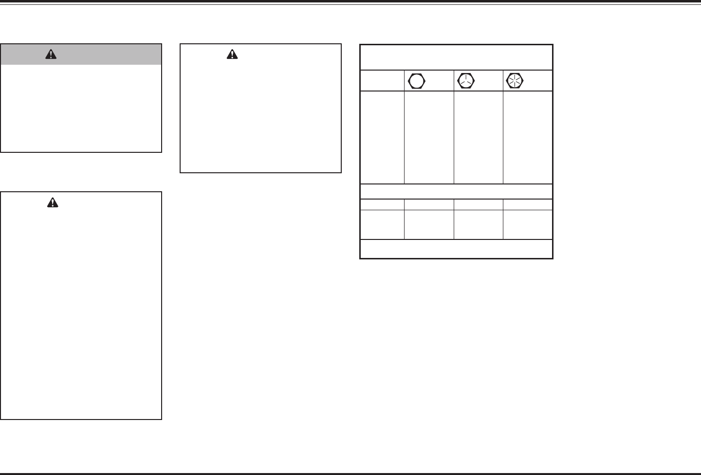
TORQUE CHART
CAUTION
Read instructions before
assembling. Fasteners should
be finger tight until instructed
to tighten according to torque
chart. Use standard methods
and practices when attaching
snowplow including proper
personal protective safety
equipment.
Recommended Fastener Torque
Chart (Ft.-Lb.)
Size
SAE
Grade 2
SAE
Grade 5
SAE
Grade 8
1/4-20
5/16-18
3/8-16
3/8-24
7/16-14
1/2-13
9/16-12
5/8-11
3/4-10
7/8-9
1-8
6
11
19
24
30
45
66
93
150
150
220
9
18
31
46
50
75
110
150
250
378
583
13
28
46
68
75
115
165
225
370
591
893
Metric Grade 8.8 (Ft.-Lb.)
Size TorqueSize
Torque
M 6
M 8
M 10
M 12
M 14
M 16
7
17
35
60
95
155
These torque values apply to fasteners
except those noted in the instruction.
VENTILATION
BATTERY SAFETY
WARNING
Vehicle exhaust contains lethal
fumes. Breathing these fumes,
even in low concentrations,
can cause death. Never
operate a vehicle in an
enclosed area without venting
exhaust to the outside.
CAUTION
Batteries normally produce
explosive gases which can
cause personal injury.
Therefore, do not allow flames,
sparks or lit tobacco to come
near the battery. When
charging or working near a
battery, always cover your face
and protect your eyes, and
also provide ventilation.
Batteries contain sulfuric acid
which burns skin, eyes and
clothing.
Disconnect the battery before
removing or replacing any
electrical components.

Lit. No. 27366, Rev. 01 February 15, 2008
8
SYSTEM OVERVIEW – BLADE, T-FRAME & LIFT ASSEMBLIES
SNOWPLOW COMPONENTS
Stacking
Stop
Shoe
Handle
T-Frame
Assembly
Upper Lift Frame
Lower Lift
Frame
Lock Pin
Stand
Plow
Horn
Lift Arm
1. Install a 1" jam nut and tighten to
25 ft-lb, then loosen 1/16 turn.
2. Hold 1" cap screw and jam nut to
prevent rotation, and install
1" locknut. Tighten locknut
securely against jam nut.
NOTE: When properly adjusted,
pivot bar should pivot freely
without any looseness.
1" Locknut
1" Jam Nut
Pivot Bar
Pivot
Bushing
1" x 7"
Cap Screw
SECURING PIVOT BAR TO T-FRAME
Excerpts taken from MVP PLUS™ Snowplow Installation Instructions (Lit. No. 44229, Rev. 05).

Lit. No. 27366, Rev. 01 February 15, 2008
9
Configuration 3
Configuration 4
Pivot Pin
Pivot Pin
Pivot Plate A
(Flat Side Up)
Pivot Plate B
(Flat Side Up)
PIVOT PLATES
1. Measure the distance "d" from
the ground to the top edge of the
receiver bracket. Measure both
sides and determine average
value "d".
2. Use dimension "d" from Step 1,
and the following chart to
determine the proper pivot plate
mounting position and pivot hole
selection.
d
Top Edge of
Receiver
Pivot Plate A
(Bevel Side Up)
Pivot Pin
Pivot Pin
Pivot Plate B
(Bevel Side Up)
Configuration 1
Configuration 2
Pivot Plate Mounting and Hole Positions
for Configurations 1 & 2
Pivot Plate Mounting and Hole Positions
for Configurations 3 & 4
SYSTEM OVERVIEW – BLADE, T-FRAME & LIFT ASSEMBLIES
Pivot Plate Configuration Chart
Dimension
"d" Configuration
Stacking
Stop
13.0" – 14.5" 1 No
14.5" – 16.0" 2 No
16.0" – 17.5" 3 No
17.5" – 19.0" 4 Yes
Excerpts taken from MVP PLUS™ Snowplow Installation Instructions (Lit. No. 44229, Rev. 05).

Lit. No. 27366, Rev. 01 February 15, 2008
10
SYSTEM OVERVIEW – BLADE, T-FRAME & LIFT ASSEMBLIES
Config. 1
Config. 2
Config. 3
Config. 4
INITIAL STAND SHOE SETUP
The illustration below shows the
recommended starting positions for
configuring your stand shoes.
9-3/4" to 11-1/4"
1-3/8" to 2-1/8"
Roll Pin
STAND SHOE ADJUSTMENT
1. Attach snowplow to the vehicle
mount. With snowplow lowered
to the ground and on level
pavement, measure the
dimension from the ground to the
center of the pivot bar cap screw.
This dimension must be 9-3/4" to
11-1/4".
2. With the snowplow attached and
on the ground, place the stand
arm in the lower position with the
lock pin engaged and with the
stand shoe fully retracted in the
"up" position. Measure the
distance from the ground to the
bottom of the stand shoe. This
distance should be 1-3/8" to
2-1/8". The stand can be
adjusted to achieve this
dimension by removing the roll
pin and selecting the proper hole
in the stand stem. When the
stand height is correct, cut and
remove the spring tie.
Excerpts taken from MVP PLUS™ Snowplow Installation Instructions (Lit. No. 44229, Rev. 05).

Lit. No. 27366, Rev. 01 February 15, 2008
11
After the snowplow has been
installed on the vehicle in the correct
configuration, a fine adjustment can
be made to bring the cutting edges of
the snowplow in full contact with the
ground across the entire cutting
edge. This adjustment feature should
be used as the cutting edges begin
to wear in order to maintain an even
wear pattern across both cutting
edges and provide good scraping
action.
1. Snowplow must be installed on a
properly ballasted vehicle, in the
correct configuration.
2. Vehicle and snowplow must be
on a level surface.
3. If the optional shoe kit has been
installed on the blade, remove
the shoes during this adjustment
procedure.
4. Place blade wings in scoop
position on the ground with no
tension on lift chains.
Rear Fasteners
Front Fasteners
Pushbeam
T-Frame
5. Remove the rear pushbeam to
T-frame fasteners. Loosen the
front fasteners, and allow the
blade to find a level position.
6. Select the hole in the rear of the
T-frame that is best aligned with
the rear hole in the pushbeam,
and reinstall the rear fasteners.
Tighten all four fasteners to
250 ft-lb.
7. Raise and lower the blade
several times. The cutting edge
should be contacting the level
surface across the full length of
the cutting edge.
8. Verify that the cutting edges
remain in full contact with the
ground while the wings are
shifted from the scoop position to
a fully retracted (vee) position.
9. Reinstall blade shoes if removed
in Step 3.
Complete this procedure as often as
required to provide even cutting edge
wear. Replace the cutting edge(s)
when worn to within 1" of the
carriage bolts.
SYSTEM OVERVIEW – BLADE, T-FRAME & LIFT ASSEMBLIES
Select the hole
best aligned with
rear hole in
pushbeam.
CUTTING EDGE WEAR AND LEVELING ADJUSTMENT PROCEDURE
Excerpts taken from MVP PLUS™ Snowplow Installation Instructions (Lit. No. 44229, Rev. 05).

Lit. No. 27366, Rev. 01 February 15, 2008
12
1. Insert the threaded rod in
through the hole in the channel
weldment. Be sure the threaded
hole in the tab on the rod is
nearest to the channel.
CAUTION
Servicing the trip springs
without special tools and
knowledge could result in
personal injury.
2. Place the assembly on to the top
anchor above the spring as
illustrated. Be sure to place the
spring bar in between the tabs on
the rod. Insert the 1/2" x 1-1/2"
Gr. 5 cap screw through the
outside tab, through the hole in
the spring bar, and tighten into
the threaded hole.
3. Drop the 1/2" flat washer Gr. 8
over the threaded rod and fasten
the nut to the threaded rod.
Tighten the nut until the spring
bar is raised enough to insert the
pin through the pin hole. Center
the pin within the hole.
4. Loosen the nut to lower the
spring bar. Remove the spring
tool assembly by removing the
1/2" cap screw.
5. Remove the spring from the
blade by removing the bolt from
the bottom of the spring bar.
6. Insert the new spring with the
spring bar up through the top
anchor on the blade. Fasten the
bottom of the spring bar to the
anchor on the trip edge with the
previously removed fasteners.
Tighten.
7. Repeat Steps 1 and 2 above.
8. Repeat Step 3 above, except
remove the pin from the spring bar.
9. Repeat Step 4 above.
Channel
Rod
1/2" x 1-1/2"
Cap Screw Gr. 5
1/2" Coupling
Nut
1/2" Flat Washer Gr. 8
1/4" x 1-1/4"
Pin
SYSTEM OVERVIEW – BLADE, T-FRAME & LIFT ASSEMBLIES
BLADE SPRING REPLACEMENT TOOL (PN 20043)
Excerpts taken from Removable Spring Tool Installation Instructions (Lit. No. 6486, Rev. 02).

Lit. No. 27366, Rev. 01 February 15, 2008
13
LIFT ARM AND LIFT RAM INSTALLATION
Lift Arm
3/4" Flat
Washer
Cotter Pin
Lift
Arm
Lift Frame
Vertical
Support
3/4" Plastic
Washer
3/4" x 3-1/4"
Clevis Pin
3/4" x 3-1/4" Clevis Pin
3/4" x 3"
Heat Treated (HT) Pin
3/4"
Washer
Lift Ram
Cotter Pin
Cotter Pin
3/4"
Washer
SYSTEM OVERVIEW – BLADE, T-FRAME & LIFT ASSEMBLIES

Lit. No. 27366, Rev. 01 February 15, 2008
14
SYSTEM OVERVIEW – BLADE, T-FRAME & LIFT ASSEMBLIES
HEADLAMP BEAM AIMING
Torque headlamp fasteners to 45 ft-lb
once correct visual aim is achieved.
1. Place vehicle on a level surface
25 feet in front of a matte-white
screen, such as a garage door.
The screen should be
perpendicular both to the ground
and to the vehicle centerline.
2. The vehicle should be equipped
for normal operation. The
snowplow blade should be in
place and in raised position. Below
are steps listed by the Society of
Automotive Engineers (SAE)
pertinent to headlamp aiming in
specification #SAE J599d.
3. Prepare vehicle for headlamp
aim or inspection. Before
checking beam aim, the
inspector will:
a. Remove ice or mud from
under fenders.
b. Set tire inflation pressures to
the values specified on
vehicle information label.
c. Check springs for sag or
broken leaves.
d. See that there is no load in
the vehicle other than the
driver and ballast as specified
in the Selection List.
e. Check functioning of any
automatic vehicle leveling
systems and specific
manufacturer's instructions
pertaining to vehicle
preparation for headlamp
aiming.
f. Clean lenses.
g. Check for bulb burnout and
proper beam switching.
h. Stabilize suspension by
rocking vehicle sideways.
4. Mark (or tape) the vertical
centerline of the snowplow
headlamps and the vertical
centerline of the vehicle on the
screen. Mark the horizontal
centerline of the snowplow
headlamps on the screen
(distance from ground to
snowplow headlamp centers).
5. Align the top edge of the high
intensity zone of the snowplow
lower beam below the horizontal
centerline and the left edge of
the high intensity zone on the
vertical centerline for each
snowplow headlamp. (Refer to
diagram.)
Vertical
Centerline
ahead of DS
Snowplow
Headlamp
Align with
vehicle
centerline.
Vertical
Centerline
ahead of PS
Snowplow
Headlamp
Screen
Located
25 Feet from
Snowplow
Headlamps
Horizontal
Centerline
of Snowplow
Headlamps
High Intensity Zones
of Snowplow Headlamps
on Low Beam
Excerpts taken from Snowplow Headlamp Beam Aiming Instructions (Lit. No. 27769, Rev. 02).

Lit. No. 27366, Rev. 01 February 15, 2008
15
SYSTEM OVERVIEW – BLADE, T-FRAME & LIFT ASSEMBLIES
VEHICLE LIGHTING CHECK
1. Check the operation of vehicle
lights and then snowplow lights
with snowplow mounted to
vehicle and all harnesses
connected.
Turn signals and parking lamps
Parking lamps ON
• Both vehicle and snowplow
parking lamps should be ON at
the same time.
Driver-side turn signal ON
• Both vehicle and snowplow
driver-side turn signal lamps
should flash at the same time.
Passenger-side turn signal ON
• Both vehicle and snowplow
passenger-side turn signal
lamps should flash at the same
time.
Headlamps
Move vehicle headlamp switch to
the "ON" position. Connecting
and disconnecting the headlamp
harness plug should switch
between vehicle and snowplow
headlamps as follows:
Headlamp harness plug
DISCONNECTED
• Vehicle headlamps should be
ON.
• Snowplow headlamps should
be OFF.
Headlamp harness plug
CONNECTED
• Snowplow headlamps should
be ON.
• Vehicle headlamps should be
OFF.
Dimmer switch should dim
whichever headlamps are
operating. The high beam
indicator on the dash should light
when either set of headlamps is
on high beam.
Daytime Running Lamps (DRLs)
With headlamp switch OFF,
activate the DRLs.
Headlamp harness plug
DISCONNECTED
• Vehicle DRLs should be ON.
• Snowplow headlamps should be
OFF.
Headlamp harness plug
CONNECTED AND vehicle uses
the headlamp bulbs for DRLs:
• Snowplow headlamps should
be ON in DRL mode (with
reduced intensity compared to
high or low beam).
• Vehicle DRLs should be OFF.
Headlamp harness plug
CONNECTED AND vehicle uses
lamps other than the headlamp
bulbs for DRLs:
• Snowplow headlamps should
be ON in DRL mode (with
reduced intensity compared to
high or low beam).
• Vehicle DRLs should be ON.
• Vehicle headlamps should be
OFF.
Joystick Control or
CabCommand Control
The control indicator light should
light whenever the control
ON/OFF switch and the ignition
(key) switches are both in the
"ON" position. The snowplow
plugs do need to be connected to
the vehicle harness connectors.
2. Connect all snowplow and
vehicle harnesses. Raise the
snowplow and aim snowplow
headlamps according to the
Snowplow Headlamp Beam
Aiming instructions included with
the headlamps and any state or
local regulations.
3. Check aim of vehicle headlamps
with snowplow removed.
4. When the snowplow is removed
from the vehicle, install plug
covers on the vehicle battery
cable and lighting harness. Insert
the snowplow battery cable and
lighting harness into the cable
boot on the snowplow.
CAUTION
On 2-plug electrical systems,
plug covers shall be used
whenever snowplow is
disconnected. Vehicle Battery
Cable is 12-volt unfused source.
Excerpts taken from MVP PLUS™ Snowplow Installation Instructions (Lit. No. 44229, Rev. 05).

Lit. No. 27366, Rev. 01 February 15, 2008
16
Breather
Quill
Reservoi
r
Valve
Manifold
Motor
Drain
Cap
Fill
Plug
SYSTEM OVERVIEW – HYDRAULIC
Western Products' FloStat hydraulic
system delivers fast and uniform
speed for lifting and angling. The
system raises the blade in two
seconds, and all angling functions
are less than five seconds.
Relief Valve Settings
• Pump Relief Valve (1)
2250 psi
2-1/2 turns CCW from fully seated
• Base-End Relief Valves (4)
4600 psi
1-1/4 turns CCW from fully seated
• Rod-End Relief Valves (2) 3700 psi
1-1/4 turns CCW from fully seated
CAUTION
Do not mix different types of
hydraulic fluid. Some fluids are
not compatible and may cause
performance problems and
product damage.
Electrical System (Approximate)
• Solenoid Coil Resistance =
7 ohm at room temperature
• Solenoid Coil Amp Draw =
1.5 Amps
• Motor Relay Coil Resistance =
13.5 ohm @ 25° C
• Motor Relay Amp Draw = 0.7 Amp
• Maximum Motor Amp Draw =
250 Amps over relief at 2250 psi
• Switch Accessory Lead Draw =
0.75 Amp
Fastener Torque
System Capacity
• Unit Reservoir = 1-3/4 Quarts
• System Total = 2-3/8–2-3/4 Quarts
Hydraulic Fluid
Use WESTERN
®
High Performance
Fluid to –40°F (–40°C) or other fluid
conforming to military specification
MIL-H-5606A, such as Mobil Aero
HFA or Shell AeroShell
®
Fluid 4. Use
of other than these recommended
fluids may cause poor hydraulic
system performance and damage to
internal components.
Pump Motor
AeroShell
®
is a registered (
®
) trademark of Shell Oil Company.
MVP PLUS™ FloStat
®
HYDRAULIC SYSTEM SPECIFICATIONS
12V DC with +/– connection
2200–2300 psi pump relief valve
4550–4650 psi base-end relief valves
3650–3750 psi rod-end relief valves
4.5" dia 1.5 kW motor
.000652 GAL/REV pump
Hydraulic Hose 1/4 SAE 100R1 and
3/8 SAE 100R17
Vehicle Control Harness Fuses
(Automotive Blade-Type)
• Park/Turn = 15 Amp
• Control = 7.5 Amp
Hydraulic Unit Harness Fuses
(Mini)
• 4 Amp
Pump Cap Screws 5/16-18 x 2-1/2 150-160 in-lb
Motor Terminals (+ and –) 5/16-18 Nut 50-60 in-lb
Motor to Manifold Cap Screws 1/4-20 x 6-1/4 30-40 in-lb
Reservoir Screws #10-24 x 5/16 30-35 in-lb
Solenoid Valves 7/8 Hex Head 19-21 ft-lb
Coil Nuts 3/4 Hex-Head Jam Nut 40-60 in-lb
Cover Screws 1/4-20 x 1/2 Shoulder Screw 60-80 in-lb
SAE O-Ring Plugs 1/8 or 5/32 Internal Hex 55-65 in-lb
Hydraulic Unit Mount Bolts 3/8-16 x 1 25-33 ft-lb
Check Valves 7/8 Hex Head 19-21 ft-lb
Secondary to Primary Manifolds 1/4-20 x 3 10-13 ft-lb
Motor Relay Small Terminals 10-32 Nut 15 in-lb max
Motor Relay Large Terminals 5/16-24 Nut 35 in-lb max
Motor Relay Mount Screws 1/4-20 x 1/4 90-100 in-lb
Plow Module Mount Screws 1/4-20 x 5/8 60-70 in-lb
Angle Ram Piston Locknuts 100-120 ft-lb
Angle Ram Gland Nuts 150-180 ft-lb

Lit. No. 27366, Rev. 01 February 15, 2008
17
SYSTEM OVERVIEW – HYDRAULIC
NOTE: Overtightening JIC hose
fitting ends will result in a
fractured fitting.
Do not use thread sealant or tape on
hoses and fittings. This could
damage product.
Use the following procedure and
fitting orientation illustrations to
install SAE O-ring fittings in valve
block and rams.
1. Remove plug from ram or
manifold port. Use a rag to catch
residual fluid when removing
manifold plugs.
2. Turn jam nut on fitting as far back
as possible.
3. Lubricate O-ring with clean
hydraulic fluid.
4. Screw fitting into port by hand as
far as it will go. The washer
should contact port face and
shoulder of jam nut threads.
5. Unscrew fitting to proper position,
no more than one full turn.
6. Use one wrench to hold fitting
body in position and tighten the
jam nut with another wrench until
the washer again contacts port
face. Tighten 1/8–1/4 turn to lock
fitting in place.
HYDRAULIC FITTING AND HOSE INSTALLATION
PS Rod End
PS Base End
DS Rod End
Lift Ram
45°
90°
Elbow
10°10°
90°
Elbow
45°
DS Base End
45°
90°
Elbow
Angle Rams
Hydraulic Unit
Long 90°
Elbows
90° Elbow
and Cap
Long 90°
Elbows
90°
Elbow
10°
45°
45°
30°
30°
10°
Use the following procedure and
illustrations to install hydraulic
hoses.
1. Attach all hoses to fittings,
routing hoses as shown. Leave
hoses finger tight at this time.
1/4" x 36" Hose
To Passenger-
Side Rod (Front)
3/8" x 45" Hose
To Driver-Side
Base (Rear)
3/8" x 38" Hose
To Passenger-
Side Base (Rear)
1/4" x 12" Hose
To Lift Ram
1/4" x 42" Hose
To Driver-Side
Rod (Front)
2. Wrap angle ram hoses with
protective hose wrap as shown.
Start wrap on base end hose so
wrap covers diagonal brace.
Group hoses away from brace
and continue wrapping, forming a
smooth outward loop to the
hydraulic unit.
3. Using a wrench to hold the hose
end in position, tighten all hose
fittings 1/8–1/4 turn past finger
tight.
Excerpts taken from MVP PLUS™ Snowplow Installation Instructions (Lit. No. 44229, Rev. 05).

Lit. No. 27366, Rev. 01 February 15, 2008
18
HYDRAULIC UNIT COMPONENTS
SYSTEM OVERVIEW – HYDRAULIC
Magnet
Fill/Fluid Level Plug
Breather
Reservoir
O-Ring
Pump
Pump
O-Ring
Quill
O-Ring
Boss Plug
Pump
Shaft
Seal
Filter
DS
Base-End Relief
Valves
DS Rod-End
Relief Valve
PS Rod-End
Relief Valve
PS
Base-End
Relief
Valves
Coil
Solenoid
Cartridge
Valve
Valve
Lock Ring
Check
Valve
Pump
Relief Valve
Primary to
Secondary
Block O-Rings
Motor
Lit. No. 27366, Rev. 01 February 15, 2008
19
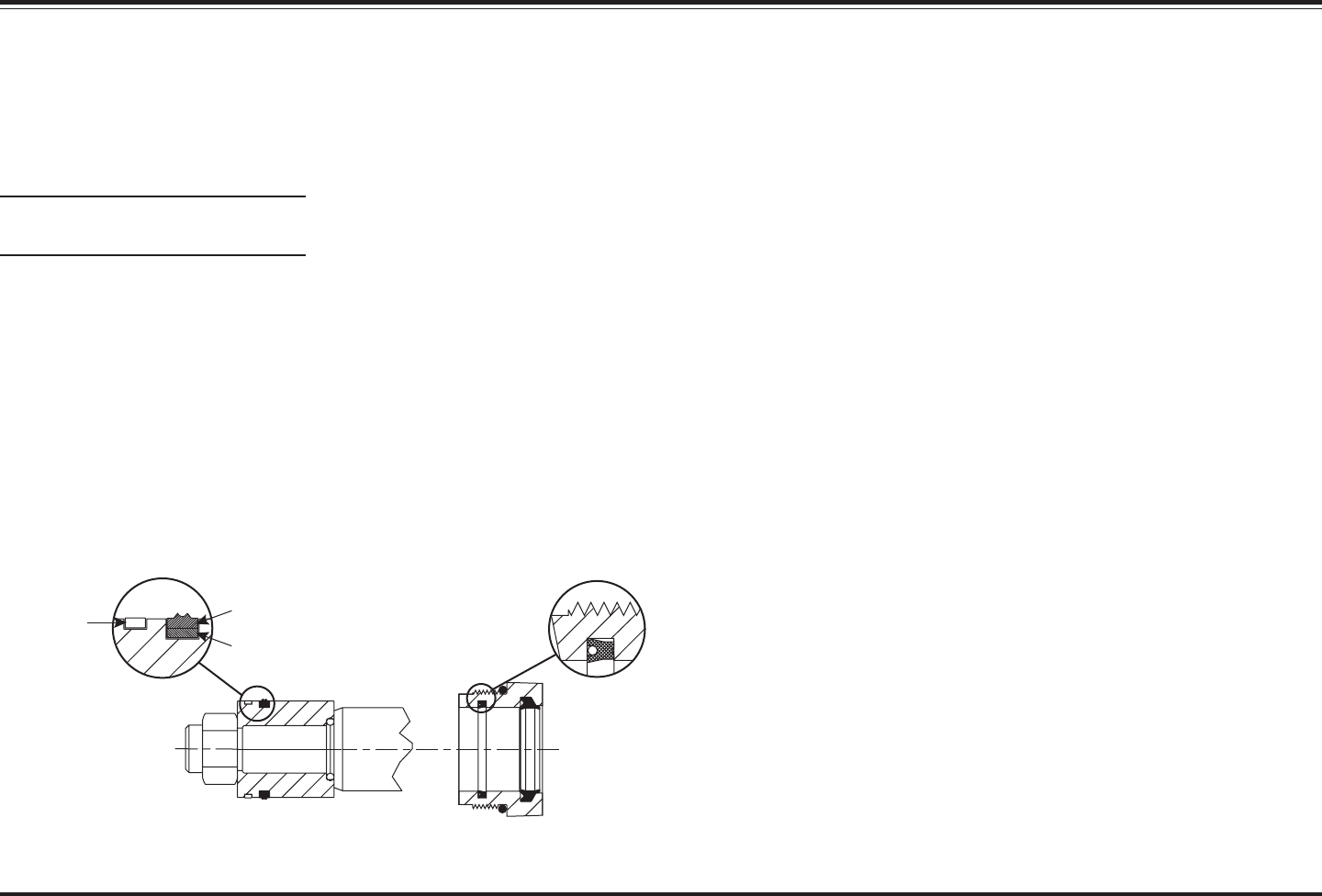
HYDRAULIC COMPONENT INSTALLATION
SYSTEM OVERVIEW – HYDRAULIC
Ram Seal Installation
1. Lubricate the seals and O-rings
with hydraulic fluid.
NOTE: Placing the part in warm
fluid will facilitate installation.
2. Install the seals and O-rings in
the exact orientation as shown.
3. For single-acting (lift) rams:
Slide the gland nut over the split
bearing end of the rod to prevent
damaging the seals.
For double-acting (angle)
rams: Remove the piston, and
slide the gland nut over the
threaded end of the rod to
prevent damaging the seals.
It is possible to remove cartridges
and check valves from a hydraulic
unit without draining the hydraulic
fluid from the reservoir.
1. Install the Diagnostic Harness
(PN 29290-1) following the
instructions included with the kit.
2. Cycle through the control
functions twice to remove the
pressure in the hydraulic unit.
3. Slowly remove the breather from
the top of the hydraulic unit.
4. Either (a) completely drain
reservoir and skip to Step 9 or
(b) proceed for instructions on
removing hydraulic components
without completely draining
reservoir.
4. For double-acting (angle) rams
only: Install the piston in the
orientation shown. Tighten piston
locknut to 100–120 ft-lb.
5. Carefully reassemble the ram.
6. Insert a 0.012" feeler gauge
between the front surface of the
cylinder tube face and the hex of
the gland nut. Tighten the gland
nut until it is snug against the
feeler gauge.
7. Remove the feeler gauge, and
tighten the gland nut an
additional 1/4 turn. This
adjustment procedure will
provide a torque of 150–180 ft-lb.
Outer Seal
Inner Backing
Ring
Double-Acting
Rams Only
Single- and
Double-Acting
Rams
Split Wear
Ring (If Used)
Cartridge & Check Valve Removal
5. Install a 3/8" barb fitting into the
top of the reservoir tank.
6. Attach a hand-operated vacuum
pump to the barb fitting.
7. Using the vacuum pump, pull a
vacuum of approximately
5"–10" Hg.
8. You should now be able to
remove cartridges and check
valves from the hydraulic unit
with minimal fluid loss. Maintain
the vacuum until the replacement
cartridge/check valve has been
installed. Once the replacement
part has been installed, release
the vacuum and remove the
3/8" barb fitting.
9. Reinstall the breather and
remove the 29290-1 Diagnostic
Harness according to the
instructions included with the kit.
Excerpts taken from Gland Nut Ram Seal Kits Service Literature (Lit. No. 28944, Rev. 01).

Lit. No. 27366, Rev. 01 February 15, 2008
20
SYSTEM OVERVIEW – HYDRAULIC
VALVE LOCATION
S4
S5
S6
S7
DS Base-End
Relief Valves
PS Base-End
Relief Valves
DS
Rod-End
Relief
Valve
PS
Rod-End
Relief
Valve
Pump Relief
Valve
Pump Pressure
Test Port
Quill
DS
Rod-End
Check
Valve
DS Base-End
Check Valve
PS
Rod-End
Check
Valve
PS Base-End
Check Valve
S8
S9
S10
S11
S1
S2
S3
Valve Type
Wire
Colors
S1
SV08-2004 White & Red
S2
SVCV08-20 Green & Red
S3
SV08-2004 Blue & Red
S4
SVCV08-20 Tan & Red
S5
SV08-2004 Black & Red
S6
SF08-2015 Yellow & Red
S7
SVCV08-20 Brown & Red
S8
SVCV08-20 Grey & Red
S9
SV08-2004 White & Red
S10
SF08-2015 Green & Red
S11
SVCV08-20 Orange & Red

Lit. No. 27366, Rev. 01 February 15, 2008
21
CARTRIDGE VALVES
The MVP PLUS™ snowplow
FloStat
®
hydraulic system performs
10 blade movement functions.
All functions require the vehicle
ignition (key) switch to be in the
"RUN" or "ACCESSORY" position
and the power to be activated on the
snowplow cab control.
Nine of the ten hydraulic functions
require energizing the electric motor
and opening solenoid cartridge
valves. The LOWER function does
not energize the motor but requires
opening of one valve.
NOTE: Cartridges S6 and S10 have
the letter "F" stamped on the end
of the stem. These cartridges have
a higher pressure rating than the
"SV" cartridges. Cartridges and
their lock rings must be installed
in the correct locations for proper
system performance.
SYSTEM OVERVIEW – HYDRAULIC
SV08-2004 S3 ON
SV08-2004 S1
MOVEMENT
BLADE
RAISE LOWER SCOOPVEE
SF08-2015 S6
EXTEND
LEFT
S4SVCV08-20 ON ON
SVCV08-20 S2 ON
SV08-2004
SVCV08-20
SVCV08-20
SV08-2004
SVCV08-20
SF08-2015
S5
S8
S11
S9
S7
S10
ON
MOTOR M ONON
ON
ON
ON
ON
ON ON
ON
ONON
ONONON
ON
ON
ONON
ONON
ANGLE
RIGHT
ANGLE
LEFT
RIGHT
RETRACT
ON
ON
ON
ON
RIGHT
EXTEND
ON
ON
ON
LEFT
RETRACT
ON
ON
ON
ON

Lit. No. 27366, Rev. 01 February 15, 2008
22
SYSTEM OVERVIEW – HYDRAULIC
CHECK VALVES
The check valves supply make-up
fluid to the low-pressure side of a
ram that is extending or retracting
through a relief valve due to impact
on one or both wings.
Tighten check valves to 19–21 ft-lb.
VALVE LOCK RINGS
Install valve lock rings over the
base-end check valves only (not
rod-end check valves). Also install
valve lock rings over cartridge valves
S6 and S10 only (not any other
cartridges).
After tightening check valve or
cartridge, place valve lock ring over
hex and tighten screw to 45–55 in-lb.
Rod-End
Check Valves
(No Lock Rings)
Base-End
Check Valves
Valve Lock
Rings
Valve Lock Ring
S6 Cartridge
S10 Cartridge
Valve Lock Ring
DS Rod-End
Check Valve
DS
Base-End
Check Valve
PS Rod-End
Check Valve
PS
Base-End
Check Valve
NOTE: Cartridges S6 and S10 have
the letter "F" stamped on the end
of the stem. These cartridges have
a higher rating than the "SV"
cartridges. Cartridges and their
lock rings must be installed in the
correct locations for proper
system performance.

Lit. No. 27366, Rev. 01 February 15, 2008
23
RELIEF VALVES
When all cartridge valves are closed,
hydraulic fluid is trapped in the ram
by the solenoid cartridge valves,
check valves, base-end relief valves
and rod-end relief valves.
When the snowplow contacts an
object while plowing, force of the
impact increases hydraulic pressure
in the base end of the ram. When
pressure exceeds 4600 psi, the ram's
base-end relief valves open, allowing
hydraulic fluid back to the reservoir.
The rod-end check valve allows fluid
to fill the rod end of the ram.
SYSTEM OVERVIEW – HYDRAULIC
PS
B
Base-End
Relief Valves
C
Pump Relief Valve
Pressure
Test Port
DS
A
Rod-End
Relief Valves
PS
DS
A (Qty 2)
B (Qty 4)
C (Qty 1)
1-1/4
1-1/4
2-1/2
3700
4600
2250*
Relief
Valve
Approx.
Pressure
(psi)
# of Turns
Out (ccw)
from
Fully Seated
* See the Pump Pressure Test
Section for details.
When the snowplow contacts an
object while back dragging, force of
the impact increases hydraulic
pressure in the rod end of the ram.
When pressure exceeds 3700 psi,
the ram's rod-end relief valve opens,
allowing hydraulic fluid into the
reservoir passage. The base-end
check valve allows fluid to fill the
base end of the ram. Because of
differential area on either side of the
ram's piston, fluid flows from the
reservoir to the base end.
NOTE: Relief valves B and
components are not interchangeable
with A and C. See Relief Valve
Inspection and Adjustment Section
for service.
NOTE: See "Striking an Object
While Plowing" Schematics for
Details.

Lit. No. 27366, Rev. 01 February 15, 2008
24
Battery
RED
BLK
4321
Vehicle
Headlamps
Park/Turn
Lamps
Vehicle
Headlamps
Park/Turn
Lamps
Factory Vehicle Harness
Factory Vehicle Harness
Vehicle Battery Cable
To Snowplow
Control
To Switched
Accessory
Fire Wall
RED
Vehicle Lighting Harness (11-Pin)
Vehicle Control Harness
Adapter
Long Plug-In Harness
Short Plug-In Harness
15-Amp Fuse (Park/Turn)
7.5-Amp Fuse (Control)
Isolation Module
BAT
WIRING
SYSTEM OVERVIEW – ELECTRICAL
CAUTION
On 2-plug electrical systems, plug
covers shall be used whenever
snowplow is disconnected.
Vehicle Battery Cable is 12-volt
unfused source.
NOTE: The Isolation Module and short plug-in harness, containing the
park and DRL lamp wire, are shown on the driver side for illustration
purposes only. Location may be different for the vehicle.

Lit. No. 27366, Rev. 01 February 15, 2008
25
ELECTRICAL ASSEMBLY
SYSTEM OVERVIEW – ELECTRICAL
C
8-Solenoid
Harness
C
B
A
Fuse
Holder
Plow Module
C
B
A
S5S4 S6 S7
S9
S8 S10 S11
A
Plow Battery Cable
B
3-Solenoid
Harness
8" Red Cable
Fuse Holder
Black
Red
S1 S2 S3
1/4-20 x 1/4
Tapping Screw (2)
90-100 in-lb
5/16-18 Nut (2)
50-60 in-lb
5/16-24 Nut (2)
Max. 35 in-lb
+
-
10-32 Nut (2)
Max. 15 in-lb
1/4-20 x 5/8
Tapping Screw (2)
60-70 in-lb
Harness Valve Type
Wire
Colors
S1
SV08-2004 White & Red
S2
SVCV08-20 Green & Red
B
S3
SV08-2004 Blue & Red
S4
SVCV08-20 Tan & Red
S5
SV08-2004 Black & Red
S6
SF08-2015 Yellow & Red
S7
SVCV08-20 Brown & Red
S8
SVCV08-20 Grey & Red
S9
SV08-2004 White & Red
S10
SF08-2015 Green & Red
C
S11
SVCV08-20 Orange & Red
Torque Specifications
All Solenoid Valves 19–21 ft-lb
All Solenoid Coil Nuts 48–60 in-lb
Motor Relay Terminals
Small 10–15 in-lb
Large
25–35 in-lb
Motor Terminals 50–60 in-lb

Lit. No. 27366, Rev. 01 February 15, 2008
26
COVER AND FINAL ASSEMBLY
SYSTEM OVERVIEW – ELECTRICAL
Before any service, remove breather slowly
to relieve reservoir pressure.
Use long cable tie to secure cable
in original position.
Apply dielectric grease to terminals.
Fit top retainer ring
over cover ridges.
Breather must be installed
before operating snowplow.
1/4-20 x 1/2 Round Washer-Head
Shoulder Screw (5) – 60-80 in-lb.
3/8-16 x 1 Hex Cap Screw (3)
25-33 ft-lb.
Short cable tie holds
cable in cover slot.
Fit bottom retainer ring
into cover ridges.

Lit. No. 27366, Rev. 01 February 15, 2008
27
SYSTEM OVERVIEW – CONTROLS
GENERAL INFORMATION
The MVP PLUS™ snowplow is
operated by with one of two special
controls—the CabCommand 9-button
hand-held control or a joystick-style
control. The controls allow you to go
from a vee, to a scoop, to a standard
straight-blade snowplow, all at the
touch of a button or single-lever
movement.
Each control has its own ON/OFF
switch with an indicator light to show
WARNING
To prevent accidental
movement of the blade, always
turn the ON/OFF switch to OFF
whenever the snowplow is not
in use. The control indicator
light will turn off.
when the control is powered up. Your
vehicle ignition (key) switch controls
a fused circuit that powers your cab
control directly from the battery.
The ON/OFF switch on the cab
control allows you to turn OFF the
control and prevent blade movement
even when the ignition switch is ON.
The control ON/OFF switch serves
as an emergency stop if required.
All controls are protected by a
replaceable fuse located in the under
hood snowplow electrical system.
See Fuse Replacement in the
Maintenance section of the Owner's
Manual.
The control is able to sense a lack of
communication with the electrical
system. Should the indicator light
start to flash, refer to the
Control/Cable/Plow Module Test.
MVP PLUS™
Joystick Control
MVP PLUS™
Hand-Held Control
Indicator Light
Indicator Light
ON/OFF Switch
(Emergency Stop)

Lit. No. 27366, Rev. 01 February 15, 2008
28
1. Turn the vehicle ignition switch to
the "ON" or "ACCESSORY"
position.
2. Press the ON/OFF button on the
control. The power indicator light
glows red, indicating the control
is ON. The indicator light glows
red whenever the control and the
vehicle ignition switch are both
ON and the electrical
connections to the snowplow are
completed.
The ON/OFF button operates as
an emergency stop if required.
Function Time-Outs
All control functions, except
LOWER/FLOAT, time out (stop)
automatically after a period of time.
This is to limit the amount of
electrical energy required from the
vehicle.
NOTE: If control function times out
before desired blade movement is
complete, release button and
press again.
Automatic Shutdown
The control will automatically turn
OFF after being idle for 20 minutes.
SYSTEM OVERVIEW – CONTROLS
MVP PLUS™ CabCommand HAND-HELD CONTROL
WARNING
To prevent accidental
movement of the blade, always
push button to switch the
control OFF whenever the
snowplow is not in use. The
control indicator light will turn
off.
Smooth Stop
The control automatically allows the
blade to coast to a stop when the
button is released. This results in
smoother operation, reduces the
shock to the hydraulic system and
increases hose and valve life.
RAISE
LOWER
R
L
ON/OFF
FLOAT
SCOOP
WING
VEE
WING
Power Indicator
Light (red)
ON/OFF
Button
(Emergency
Stop)
Float Light
(green)
Excerpts taken from UltraMount
®
Owner's Manual (Lit. No. 44230, Rev. 06).

Lit. No. 27366, Rev. 01 February 15, 2008
29
Scoop/Retract (Vee) Blade
Position
The two round buttons located to the
left and right of the RAISE button
move both wings at the same time
into the blade positions described in
the following table:
Function Description of Operation
SCOOP
Press this button to extend both wings forward into the scoop position.
Function times out after 5.0 seconds.
RETRACT
(VEE)
Press this button to draw both wings into the fully retracted (vee) position.
Function times out after 3.0 seconds.
Function Description of Operation
L WING
Press the round WING button on the left side of the control to move the
left wing. The first time the button is pressed after the control is turned ON
or another function is used, the wing will extend. Repeated use of the
same button, without using another function, results in movement in the
opposite direction from the previous movement. Function times out after
3.0 seconds.
R WING
Press the round WING button on the right side of the control to move the
right wing. The first time the button is pressed after the control is turned
ON or another function is used, the wing will extend. Repeated use of the
same button, without using another function, results in movement in the
opposite direction from the previous movement. Function times out after
3.0 seconds.
SCOOP
FLOAT ON / OFF
VEE
RAISE
LOWER
WING
LR
WING
Control Functions
Raise, Lower, Float, Angle
The four diamond-shaped buttons in
the center of the control face, when
pressed, will result in the movements
described in the table:
SYSTEM OVERVIEW – CONTROLS
Wing Positions
The two round buttons located to the
left and right of the LOWER button
move either wing independently of
the other as described in the
following table:
Float Light
(green)
LOWER
WING
SCOOP
LR
FLOAT ON / OFF
VEE
WING
RAISE
Function Description of Operation
RAISE
Press this button to raise the snowplow and cancel the FLOAT mode.
Function times out after 4.0 seconds.
LOWER
Press this button to lower the snowplow. Release the button to stop blade
at desired height.
FLOAT
Press the LOWER button and hold 3/4 second to activate this mode. The
FLOAT indicator light in the upper left corner of the control face will
illuminate. The blade will lower to the ground surface and follow the
contour of the surface as it dips or raises. Function does not time out, but
control will shut down after 20 minutes of nonuse.
Press RAISE button momentarily to cancel FLOAT. Angling left or right will
interrupt (stop) the FLOAT function while the blade angles. FLOAT will
resume when angling is complete.
L
(Angle
Left)
With wings in a straight line, press the L button to move both wings to the
angle left position to cast snow to the driver's left side. The left wing
retracts while the right wing extends. Function times out after 3.0 seconds.
R
(Angle
Right)
With wings in a straight line, press the R button to move both wings to the
angle right position to cast snow to the driver's right side. The right wing
retracts while the left wing extends. Function times out after 3.0 seconds.
Excerpts taken from UltraMount
®
Owner's Manual (Lit. No. 44230, Rev. 06).

Lit. No. 27366, Rev. 01 February 15, 2008
30
WARNING
To prevent accidental
movement of the blade, always
move the ON/OFF switch to
OFF whenever the snowplow
is not in use. The control
indicator light will turn off.
1. Turn the vehicle ignition switch to
the "ON" or the "ACCESSORY"
position.
2. Move the slide switch on the side
of the control to the "ON"
position. The power indicator
light glows red, indicating the
control is ON. The indicator light
glows red whenever the control
and the vehicle ignition switch
are both ON and the electrical
connections to the snowplow are
completed.
The ON/OFF switch operates as
an emergency stop if required.
Function Time-Outs
All control functions, except LOWER/
FLOAT, time out (stop) automatically
after a period of time. This is to limit
the amount of electrical energy
required from the vehicle.
NOTE: If control function times out
before desired blade movement is
complete, release the lever to the
center position, then move back
into the desired function.
Automatic Shutdown
The control will automatically turn
OFF after being idle for 20 minutes.
To reactivate the control after a shut
down, move the ON/OFF switch to
OFF, then back to ON.
Smooth Stop
The control automatically allows the
blade to coast to a stop when the
lever returns to center position. This
results in smoother operation,
reduces the shock to the hydraulic
system and increases hose and
valve life.
Control Lever Movement
From the center position, the control
lever can be moved in one of eight
(8) directions to control various
movements of the snowplow blade.
To change from one movement of the
blade to another, the control lever
must be moved back to the center
position before selecting the desired
function. Whenever the lever is
released, it should spring back into
the center position to stop any blade
movement.
SYSTEM OVERVIEW – CONTROLS
MVP PLUS™ JOYSTICK CONTROL
LOWER
RAISE
VEE
FLOATON / OFF
WINGWING
SCOOP
R
L
Power Indicator
Light (red)
Float Light
(green)
ON/OFF
Switch
(Emergency
Stop)
Excerpts taken from UltraMount
®
Owner's Manual (Lit. No. 44230, Rev. 06).

Lit. No. 27366, Rev. 01 February 15, 2008
31
Function Description of Operation
SCOOP
Move the control lever toward the word SCOOP on the control face to
extend both wings forward into the scoop position. Function times out
after 5.0 seconds.
RETRACT
(VEE)
Move the control lever toward the word RETRACT (VEE) on the control
face to draw both wings into the fully retracted (vee) position. Function
times out after 3.0 seconds.
Function Description of Operation
L WING
Move the control lever toward the left side of LOWER on the control face
to move the left wing. The first time the lever is moved into the slot after
the control is turned ON or another function is used, the wing will extend.
Repeated use of lever in the same slot, without using another function,
results in movement in the opposite direction from the previous
movement. Function times out after 3.0 seconds.
R WING
Move the control lever toward the right side of LOWER on the control
face to move the right wing. The first time the lever is moved into the slot
after the control is turned ON or another function is used, the wing will
extend. Repeated use of lever in the same slot, without using another
function, results in movement in the opposite direction from the previous
movement. Function times out after 3.0 seconds.
Function Description of Operation
RAISE
Move the control lever toward the top of the control body to raise the
snowplow and cancel the FLOAT mode. Function times out after 3.0
seconds.
LOWER
Move the control lever toward the bottom of the control body to lower the
snowplow. Release the lever to stop blade at desired height.
FLOAT
Move the control lever to the LOWER position and hold 3/4 second to
activate this mode. The FLOAT indicator light in the upper right corner of
the control face will illuminate. The blade will lower to the ground surface
and follow the contour of the surface as it dips or raises. Function does
not time out; however, control will shut down after 20 minutes of nonuse.
Move lever to the RAISE position momentarily to cancel FLOAT. Angling
left or right will interrupt (stop) the FLOAT function while the blade angles.
FLOAT will resume when angling is complete.
L
(Angle
Left)
With wings in a straight line, move the control lever straight to the left to
move both wings to the angle left position to cast snow to the driver's left
side. The left wing retracts while the right wing extends. Function times
out after 3.0 seconds.
R
(Angle
Right)
With wings in a straight line, move the control lever straight to the right to
move both wings to the angle right position to cast snow to the driver's
right side. The right wing retracts while the left wing extends. Function
times out after 3.0 seconds.
LOWER
RAISE
VEE
FLOATON / OFF
WINGWING
SCOOP
R
L
Float Light
(green)
Control Functions
Raise, Lower, Float, Angle
Movement of the control lever in
straight lines up and down or from
side to side on the control body will
result in the blade movements as
described in the following table:
SYSTEM OVERVIEW – CONTROLS
Excerpts taken from UltraMount
®
Owner's Manual (Lit. No. 44230, Rev. 06).
Scoop/Retract (Vee) Blade Position
Moving the control lever from the
center position toward the word
SCOOP or RETRACT (VEE) on the
face of the control body will cause
both wings to move at the same time
into the blade positions described in
the following table:
Wing Positions
Move the control lever from the
center position toward the word,
WING, on either side of the face of
the control body. The use of either of
these slots will allow movement of
either wing independently of the
other as described in the following
table:

Lit. No. 27366, Rev. 01 February 15, 2008
32
THEORY OF OPERATION
SNOWPLOW HEADLAMPS
The Isolation Module acts as an
electrical hub, automatically directing
vehicle power to the appropriate
vehicle or snowplow lighting devices,
while also supplying battery power to
the snowplow control.
The vehicle high and low beams
enter and exit the Isolation Module
through positions 3 (left-side lighting)
and position 4 (right-side lighting).
Park, turn and DRL signals also enter
through positions 3 and 4. The output
of the vehicle dimmer switch is
directed to the Isolation Module via
the long and short plug-in harnesses.
All snowplow lighting exits the
Isolation Module through position 2.
When the snowplow is not attached
to the vehicle, the signal passes
through the normally closed relay
contacts to the vehicle headlamps.
During this time, the Isolation Module
is inactive, placing no current draw
on the vehicle's electrical system.
With the snowplow attached, the
Isolation Module is still inactive until
either of the two following conditions
are met: The vehicle parking lights
are turned ON or the vehicle ignition
switch is turned ON.
Turning ON the vehicle parking lights
activates a series of relays,
automatically transferring the vehicle
high and low beams to the snowplow
while supplying battery power directly
to the snowplow parking lights.
Turning ON the vehicle ignition
switch energizes a snowplow control
relay, supplying vehicle battery power
directly to the control via the vehicle
control harness. The vehicle ignition
switch also supplies power to the
vehicle turn signals. Activating the
vehicle turn signals energizes turn
signal relays, which supply vehicle
battery power directly to the
snowplow turn signals.
SNOWPLOW DAYTIME
RUNNING LIGHTS
Because Daytime Running Lamps
(DRLs) are controlled differently on
some vehicles, two Isolation Modules
have been developed.
The standard Isolation Module
transfers the DRL output from the
vehicle headlamps to the snowplow
headlamps when the vehicle ignition
switch is turned ON and the
snowplow is attached.
The second Isolation Module,
designed for vehicles with dedicated
DRL bulbs, senses the vehicle in the
DRL mode and a series of relays
energize, placing the snowplow low
beams in series. This Isolation
Module does not turn OFF the
vehicle's dedicated DRLs.
SNOWPLOW HYDRAULICS
The MVP PLUS™ snowplow
hydraulic system performs ten blade
movements.
All movements require the vehicle
ignition (key) switch to be in the
"RUN" or "ACCESSORY" position
and the power to be activated on the
snowplow cab control.
Nine of the ten hydraulic movements
require energizing the electric motor
and appropriate solenoid cartridge
valves. The tenth function, lower,
does not energize the motor but
requires activating a cartridge valve.
Power from the vehicle battery is
supplied to the solenoid coils and the
snowplow control via the Isolation
Module. The solenoid cartridge
valves operate in various
combinations, directed by the cab
control, to send hydraulic fluid to the
snowplow lift and angle rams or back
to the reservoir.
MOVEMENT
BLADE
RAISE
LOWER
ANGLE
RIGHT
ANGLE
LEFT SCOOPVEE
EXTEND
LEFT
LEFT
RETRACT
RIGHT
EXTEND
RIGHT
RETRACT

Lit. No. 27366, Rev. 01 February 15, 2008
33
ELECTRICAL & HYDRAULIC SCHEMATICS
The following section contains
hydraulic and electrical schematics to
help explain how the hydraulic unit
performs the different functions. A
schematic is an abstract drawing
showing the purpose of each of the
components in the system. Each
component is represented by a
graphical symbol. The hydraulic and
electrical legends describe each of
the symbols used in the schematics
for this guide.
The first two schematics show a
general overview of the complete
hydraulic and electrical systems.
Other schematics highlight the flow
of hydraulic fluid and electrical
current for each function the
hydraulic unit performs as well as the
flow of electrical current for the
snowplow and vehicle lights.
• Bold lines represent the circuit
being activated only.
• Shaded components are either
activated or shifted from their
normal position.
CROSSING WIRE
WIRE SPLICE
FUSE
SOLENOID COIL
CIRCUIT GROUND
MOTOR RELAY
BATTERY
MOTOR
IN LINE CONNECTOR
PARK/TURN LAMP
COMPONENT ENCLOSURE
PRINTED CIRCUIT BOARD
L
H
HEADLAMP
CHECK VALVE
ELECTRICAL LEGEND HYDRAULIC LEGEND
COMPONENT ENCLOSURE
FILTER, STRAINER,
DIFFUSER
ELECTRIC MOTOR
RAM
HYDRAULIC PUMP
FIXED DISPLACEMENT
LINE, TO RESERVOIR
BELOW FLUID LEVEL
FLOW, DIRECTION OF
HYDRAULIC FLUID
LINE, WORKING (MAIN)
LINES JOINING
LINES CROSSING
SPRING
SOLENOID, SINGLE WINDING
VALVE, ADJUSTABLE
PRESSURE RELIEF
VALVE, FLOW CONTROL,
ADJUSTABLE-
NON-COMPENSATED
VALVE, TWO POSITION,
TWO CONNECTION
(TWO WAY)
VALVE, TWO POSITION,
TWO CONNECTION
(TWO WAY) WITH INTEGRAL
CHECK VALVE

Lit. No. 27366, Rev. 01 February 15, 2008
34
ELECTRICAL SCHEMATIC
3
2
1
4
3
2
1
4
4-Pin Plug
(Under Dash)
RED
RED
BLK
BLK
GRN
RED
WHT
BLK
Control
RED
RED/GRN
To Switched Accessory Lead
Vehicle Control Harness, 4 Wire
1 – Red
2 – Green
3 – White
4 – Black
1 – Red (Control Power)
2 – Red (Twisted with #3)
3 – Black (Twisted with #2)
4 – Black (Control Ground)
4
2
3
1
4
2
3
1
(connector face view)
ADCB
Vehicle Battery Cable, 4 Receptacle
BLK
BLK
RED
BACD
WHT
RED
RED
CC
A
B
A
B
D
D
BLK
TAN
A
B
C
D
E
F
G
H
J
K
* HB-1(9004) A=BLUE, J=YELLOW)
** 99 DODGE RAM W/SPORT PACKAGE
PS LOW BEAM NO.2 OUT
**
PS HIGH BEAM NO.2 IN
**
DS HIGH BEAM NO.2 IN
**
DS LOW BEAM NO.2 OUT
**
PARK LAMP IN
PS TURN IN
PS COMMON OUT
PS LOW BEAM OUT
PS HIGH BEAM OUT
PS COMMON IN
PS HIGH BEAM IN
PS LOW BEAM IN
DS TURN IN
DS COMMON OUT
DS LOW BEAM OUT
DS HIGH BEAM OUT
DS COMMON IN
DS HIGH BEAM IN
DS LOW BEAM IN
A
B
C
D
E
F
G
H
J
K
Vehicle
Lighting
Harness,
11 Pin
For All
Headlamps
Except
HB-3/HB-4:
To Vehicle
Headlamps,
Park/Turn
and Factory
Vehicle
Harnesses
PS COMMON OUT
PS COMMON IN
PS HIGH BEAM OUT
PS LOW BEAM OUT
PS TURN IN
BLU
LTBLU
RED
ORG
PUR
A
B
C
D
E
F
G
H
J
K
DS COMMON IN
DS COMMON OUT
PS LOW BEAM IN
PS HIGH BEAM IN
DS HIGH BEAM OUT
DS LOW BEAM OUT
DS TURN IN
PARK LAMP IN
DRL SIGNAL IN
LTBLU
YEL
BLU
GRN
BRN
PUR
ORG
RED
PNK
DS LOW BEAM IN
DS HIGH BEAM IN
YEL
GRN
A
B
C
D
E
F
G
H
J
K
WHT/YEL
PUR
LTBLU
ORG
RED
BLU
*
Isolation Module
A
B
C
D
E
F
G
H
J
K
WHT
GRN
WHT/YEL
GRN
YEL
*
BLU
*
RED
ORG
LTBLU
PUR
BRN
YEL
*
GRN
BLU/ORN
LTBLU
BRN
PUR
GRY
BLK/WHT
WHT/YEL
BLK/ORN
BLK
From Vehicle
Control
Harness
From Vehicle
Lighting
Harness
From DS
Vehicle
Headlamps
From PS
Vehicle
Headlamps
DKBLU/WHT
WHT
RED/WHT
RED/BLK
DKBLU/RED
RED/YEL
BLU
RED
A
B
C
D
E
F
G
H
J
K
Plow
Lighting
Harness,
11 Pin
TURN
PARK
COM
HIGH
LOW
BEAM
PARK
TURN
HIGH
LOW
BEAM
LOW-6A
TURN-8B
COM-11B
PARK
HIGH-4C
C
A
BB
C
A
BB
C
A
B
C
A
B
COM-5B
LOW-1A
HIGH-3C
TURN-9B
PARK
COM
TURN-9B
COM-11B
PARK
LOW-6A
TURN-8B
COM-5B
COM
HIGH-4C
LOW-1A
HIGH-3C
COM
8
11
10
9
7
5
6
3
4
1
2
8
9
10
11
4
6
5
7
2
3
1
BLK/WHT
BLK/ORN
WHT/YEL
WHT
BLU/ORN
BLK
BLK/ORN
GRY
PUR
BRN
LTBLU
A
C
B
BLK/ORN
Plow Module
WHT
TAN
BLK
BLK
RED
4 Amp Fuse: S1, S2, S3
4 Amp Fuse: Motor Relay
4 Amp Fuse: S4, S5, S6, S7
4 Amp Fuse: S8, S9, S10, S11
–
Pump
Motor
RED
RED
Motor
Relay
S1
S2
S3
BLK
RED
RED
WHT
GRN
BLU
RED
A
G
A
B
C
D
E
F
K
H
J
G
A
B
C
D
E
F
K
H
J
G
A
B
C
D
E
F
K
H
J
G
A
B
C
D
E
F
K
H
J
B
S10
S9
S8
S11
S7
S6
GRY
RED
WHT
GRN
ORN
RED
BRN
YEL
S4
S5
BLK
TAN
BB
A
C
A
HH
D
C
F
G
EE
D
C
F
G
K
J
K
J
B
C
A
Configuration
Plug or
Dust Cover
15 Amp
Park/Turn
Fuse
7.5 Amp
Control
Fuse
Battery
Port #1 Adapter
4
3
4
3
2
1
+
+
–
For HB-3/HB-4
Headlamps:
To Vehicle
Headlamps,
Park/Turn, DRL
and Factory
Vehicle
Harnesses
RED
BLK
RED
Located at Front of Vehicle
Snowplow Assembly
Passenger-Side Plow Lamp
Driver-Side Plow Lamp
CAUTION
On 2-plug electrical systems, plug covers shall
be used whenever snowplow is disconnected.
Vehicle Battery Cable is 12-volt unfused source.

Lit. No. 27366, Rev. 01 February 15, 2008
35
HYDRAULIC SCHEMATIC
Relief Valve Settings
Pump
Ram, Base-End
Ram, Rod-End
2250 psi
3700 psi
4600 psi
SV08-2004 S3 ON
SV08-2004 S1
MOVEMENT
BLADE
RAISE LOWER SCOOPVEE
SF08-2015 S6
EXTEND
LEFT
S4SVCV08-20 ON ON
SVCV08-20 S2 ON
SV08-2004
SVCV08-20
SVCV08-20
SV08-2004
SVCV08-20
SF08-2015
S5
S8
S11
S9
S7
S10
ON
MOTOR M ONON
ON
ON
ON
ON
ON ON
ON
ONON
ONONON
ON
ON
ONON
ONON
ANGLE
RIGHT
ANGLE
LEFT
RIGHT
RETRACT
ON
ON
ON
ON
RIGHT
EXTEND
ON
ON
ON
LEFT
RETRACT
ON
ON
ON
ON
PRESSURE TEST PORT
DRAIN
QUILL
PUMP
RELIEF
VALVE
S10S5
S6
S4
S11
S8
S9
S3
S2
S1
RELIEF
VALVES
DS BASE
RELIEF
VALVES
PS BASE
CHECK
VALVE
DS BASE
RELIEF
VALVE
DS ROD
RELIEF
VALVE
PS ROD
CHECK
VALVE
PS BASE
CHECK
VALVE
DS ROD
CHECK
VALVE
PS ROD
DS
PS LIFT
M
S7
SECONDARY BLOCK ASSEMBLY
PRIMARY BLOCK ASSEMBLY

Lit. No. 27366, Rev. 01 February 15, 2008
36
RAISE – ELECTRICAL
Plow Module
4 Amp Fuse: Motor
Relay
4 Amp Fuse: S1, S2, S3
Pump
Motor
Motor
Relay
GG
A
A
A
B
C
E
D
F
B
C
D
E
F
H
KK
H
JJ
A
B
A
GG
B
D
C
F
E
D
B
C
F
E
H
KK
H
JJ
4 Amp Fuse: S8, S9,
S10, S11
4 Amp Fuse: S4, S5,
S6, S7
Wire Side View
10-Pin Connector
BB
A
C
A
HH
D
C
F
G
EE
D
C
F
G
K
J
K
J
WHT
TAN
BLK
RED
RED
RED
S1
S2
S3
BLK
RED
RED
WHT
GRN
BLU
RED
12V
COM
12V
M/R
S2
S3
S1
12V
S10
S9
S8
S11
S7
S6
GRY
RED
WHT
GRN
ORN
RED
BRN
YEL
S4
S5
BLK
TAN
S9
S8
S5
12V
S10
S11
S7
S6
S4
12V
E
D
B
C
A
F
G
J
H
K
+
–
BLK
RED
System Response
1. By activating the RAISE function
on the cab control, the control
sends a signal to the Plow
Module to complete the ground
path for the electrical circuit,
activating the motor relay and
solenoid cartridge valve S2.
2. Hydraulic fluid from the pump
flows through S2 and fills the
base end of the lift ram,
extending the rod.
NOTE: Battery voltage is supplied
to the Plow Module, the motor
relay and the 11 solenoid coils
when the snowplow is connected
to the vehicle.

Lit. No. 27366, Rev. 01 February 15, 2008
37
RAISE – HYDRAULIC
Relief Valve Settings
Pump
Ram, Base-End
Ram, Rod-End
2250 psi
3700 psi
4600 psi
PRESSURE TEST PORT
DRAIN
QUILL
PUMP
RELIEF
VALVE
S10S5
S6
S4
S11
S8
S9
S3
S2
S1
RELIEF
VALVES
DS BASE
RELIEF
VALVES
PS BASE
CHECK
VALVE
DS BASE
RELIEF
VALVE
DS ROD
RELIEF
VALVE
PS ROD
CHECK
VALVE
PS BASE
CHECK
VALVE
DS ROD
CHECK
VALVE
PS ROD
DS
PS LIFT
M
S7
SECONDARY BLOCK ASSEMBLY
PRIMARY BLOCK ASSEMBLY
SV08-2004 S3 ON
SV08-2004 S1
MOVEMENT
BLADE
RAISE LOWER SCOOPVEE
SF08-2015 S6
EXTEND
LEFT
S4SVCV08-20 ON ON
SVCV08-20 S2 ON
SV08-2004
SVCV08-20
SVCV08-20
SV08-2004
SVCV08-20
SF08-2015
S5
S8
S11
S9
S7
S10
ON
MOTOR M ONON
ON
ON
ON
ON
ON ON
ON
ONON
ONONON
ON
ON
ONON
ONON
ANGLE
RIGHT
ANGLE
LEFT
RIGHT
RETRACT
ON
ON
ON
ON
RIGHT
EXTEND
ON
ON
ON
LEFT
RETRACT
ON
ON
ON
ON

Lit. No. 27366, Rev. 01 February 15, 2008
38
LOWER – ELECTRICAL
System Response
1. By activating the LOWER
function on the cab control, the
control sends a signal to the
Plow Module to complete the
ground path for the electrical
circuit, activating solenoid
cartridge valve S3.
2. With the weight of the snowplow
on the rod end of the lift ram and
S3 cartridge valve shifted, the lift
ram retracts. Hydraulic fluid is
pushed out of the base end,
through S3 and back to the
reservoir.
NOTE: Battery voltage is supplied
to the Plow Module, the motor
relay and the 11 solenoid coils
when the snowplow is connected
to the vehicle.
RED
Plow Module
4 Amp Fuse: Motor
Relay
4 Amp Fuse: S1, S2, S3
Pump
Motor
Motor
Relay
GG
A
A
A
B
C
E
D
F
B
C
D
E
F
H
KK
H
JJ
A
B
A
GG
B
D
C
F
E
D
B
C
F
E
H
KK
H
JJ
4 Amp Fuse: S8, S9,
S10, S11
4 Amp Fuse: S4, S5,
S6, S7
Wire Side View
10-Pin Connector
BB
A
C
A
HH
D
C
F
G
EE
D
C
F
G
K
J
K
J
WHT
TAN
BLK
RED
RED
RED
S1
S2
S3
BLK
RED
RED
WHT
GRN
BLU
RED
12V
COM
12V
M/R
S2
S3
S1
12V
S10
S9
S8
S11
S7
S6
GRY
RED
WHT
GRN
ORN
RED
BRN
YEL
S4
S5
BLK
TAN
S9
S8
S5
12V
S10
S11
S7
S6
S4
12V
E
D
B
C
A
F
G
J
H
K
+
–
BLK

Lit. No. 27366, Rev. 01 February 15, 2008
39
LOWER – HYDRAULIC
Relief Valve Settings
Pump
Ram, Base-End
Ram, Rod-End
2250 psi
3700 psi
4600 psi
S3
PRESSURE TEST PORT
DRAIN
QUILL
PUMP
RELIEF
VALVE
S10S5
S6
S4
S11
S8
S9
S2
S1
RELIEF
VALVES
DS BASE
RELIEF
VALVES
PS BASE
CHECK
VALVE
DS BASE
RELIEF
VALVE
DS ROD
RELIEF
VALVE
PS ROD
CHECK
VALVE
PS BASE
CHECK
VALVE
DS ROD
CHECK
VALVE
PS ROD
DS
PS LIFT
M
S7
SECONDARY BLOCK ASSEMBLY
PRIMARY BLOCK ASSEMBLY
SV08-2004 S3 ON
SV08-2004 S1
MOVEMENT
BLADE
RAISE LOWER SCOOPVEE
SF08-2015 S6
EXTEND
LEFT
S4SVCV08-20 ON ON
SVCV08-20 S2 ON
SV08-2004
SVCV08-20
SVCV08-20
SV08-2004
SVCV08-20
SF08-2015
S5
S8
S11
S9
S7
S10
ON
MOTOR M ONON
ON
ON
ON
ON
ON ON
ON
ONON
ONONON
ON
ON
ONON
ONON
ANGLE
RIGHT
ANGLE
LEFT
RIGHT
RETRACT
ON
ON
ON
ON
RIGHT
EXTEND
ON
ON
ON
LEFT
RETRACT
ON
ON
ON
ON

Lit. No. 27366, Rev. 01 February 15, 2008
40
ANGLE RIGHT – ELECTRICAL
System Response
1. By activating the angle right (R
on the control face) function on
the cab control, the control sends
a signal to the Plow Module to
complete the ground path for
the electrical circuit, activating the
motor relay and solenoid cartridge
valves S5, S8 & S10.
2. Hydraulic fluid from the pump
flows through activated S8 and
into the rod end of the right ram,
causing it to retract.
3. The retracting PS ram pushes
the hydraulic fluid out of its base
end, through activated valve S10
and inactivated S6, then into the
base end of the DS ram causing
it to extend.
4. The extending DS ram pushes
the hydraulic fluid out of its rod
end, through activated S5 and
back to the reservoir.
NOTE: Battery voltage is supplied
to the Plow Module, the motor
relay and the 11 solenoid coils
when the snowplow is connected
to the vehicle.
RED
Plow Module
4 Amp Fuse: Motor
Relay
4 Amp Fuse: S1, S2, S3
Pump
Motor
Motor
Relay
GG
A
A
A
B
C
E
D
F
B
C
D
E
F
H
KK
H
JJ
A
B
A
GG
B
D
C
F
E
D
B
C
F
E
H
KK
H
JJ
4 Amp Fuse: S8, S9,
S10, S11
4 Amp Fuse: S4, S5,
S6, S7
Wire Side View
10-Pin Connector
BB
A
C
A
HH
D
C
F
G
EE
D
C
F
G
K
J
K
J
WHT
TAN
BLK
RED
RED
RED
S1
S2
S3
BLK
RED
RED
WHT
GRN
BLU
RED
12V
COM
12V
M/R
S2
S3
S1
12V
S10
S9
S8
S11
S7
S6
GRY
RED
WHT
GRN
ORN
RED
BRN
YEL
S4
S5
BLK
TAN
S9
S8
S5
12V
S10
S11
S7
S6
S4
12V
E
D
B
C
A
F
G
J
H
K
+
–
BLK

Lit. No. 27366, Rev. 01 February 15, 2008
41
ANGLE RIGHT – HYDRAULIC
Relief Valve Settings
Pump
Ram, Base-End
Ram, Rod-End
2250 psi
3700 psi
4600 psi
PRESSURE TEST PORT
DRAIN
QUILL
PUMP
RELIEF
VALVE
S10S5
S6
S11
S9
S3
S2
S1
RELIEF
VALVES
DS BASE
RELIEF
VALVES
PS BASE
CHECK
VALVE
DS BASE
RELIEF
VALVE
DS ROD
RELIEF
VALVE
PS ROD
CHECK
VALVE
PS BASE
CHECK
VALVE
DS ROD
CHECK
VALVE
PS ROD
DS
PS LIFT
M
S7
S4
SECONDARY BLOCK ASSEMBLY
PRIMARY BLOCK ASSEMBLY
S8
SV08-2004 S3 ON
SV08-2004 S1
MOVEMENT
BLADE
RAISE LOWER SCOOPVEE
SF08-2015 S6
EXTEND
LEFT
S4SVCV08-20 ON ON
SVCV08-20 S2 ON
SV08-2004
SVCV08-20
SVCV08-20
SV08-2004
SVCV08-20
SF08-2015
S5
S8
S11
S9
S7
S10
ON
MOTOR M ONON
ON
ON
ON
ON
ON ON
ON
ONON
ONONON
ON
ON
ONON
ONON
ANGLE
RIGHT
ANGLE
LEFT
RIGHT
RETRACT
ON
ON
ON
ON
RIGHT
EXTEND
ON
ON
ON
LEFT
RETRACT
ON
ON
ON
ON

Lit. No. 27366, Rev. 01 February 15, 2008
42
ANGLE LEFT – ELECTRICAL
System Response
1. By activating the angle left (L on
the control face) function on the
cab control, the control sends a
signal to the Plow Module to
complete the ground path for the
electrical circuit, activating the
motor relay and solenoid
cartridge valves S4, S6 & S9,
activating these valves.
2. Hydraulic fluid from the pump
flows through activated S4 and
into the rod end of the left ram,
causing it to retract.
3. The retracting DS ram pushes
the hydraulic fluid out of its base
end, through activated S6 and
inactivated S10, then into the
base end of the PS ram, causing
it to extend.
4. The extending PS ram pushes
the hydraulic fluid out of its rod
end, through activated S9 and
back to the reservoir.
NOTE: Battery voltage is supplied
to the Plow Module, the motor
relay and the 11 solenoid coils
when the snowplow is connected
to the vehicle.
Plow Module
4 Amp Fuse: Motor
Relay
4 Amp Fuse: S1, S2, S3
Pump
Motor
Motor
Relay
GG
A
A
A
B
C
E
D
F
B
C
D
E
F
H
KK
H
JJ
A
B
A
GG
B
D
C
F
E
D
B
C
F
E
H
KK
H
JJ
4 Amp Fuse: S8, S9,
S10, S11
4 Amp Fuse: S4, S5,
S6, S7
Wire Side View
10-Pin Connector
BB
A
C
A
HH
D
C
F
G
EE
D
C
F
G
K
J
K
J
WHT
TAN
BLK
RED
RED
RED
RED
S1
S2
S3
BLK
RED
RED
WHT
GRN
BLU
RED
12V
COM
12V
M/R
S2
S3
S1
12V
S10
S9
S8
S11
S7
S6
GRY
RED
WHT
GRN
ORN
RED
BRN
YEL
S4
S5
BLK
TAN
S9
S8
S5
12V
S10
S11
S7
S6
S4
12V
E
D
B
C
A
F
G
J
H
K
+
–
BLK

Lit. No. 27366, Rev. 01 February 15, 2008
43
ANGLE LEFT – HYDRAULIC
Relief Valve Settings
Pump
Ram, Base-End
Ram, Rod-End
2250 psi
3700 psi
4600 psi
SV08-2004 S3 ON
SV08-2004 S1
MOVEMENT
BLADE
RAISE LOWER SCOOPVEE
SF08-2015 S6
EXTEND
LEFT
S4SVCV08-20 ON ON
SVCV08-20 S2 ON
SV08-2004
SVCV08-20
SVCV08-20
SV08-2004
SVCV08-20
SF08-2015
S5
S8
S11
S9
S7
S10
ON
MOTOR M ONON
ON
ON
ON
ON
ON ON
ON
ONON
ONONON
ON
ON
ONON
ONON
ANGLE
RIGHT
ANGLE
LEFT
RIGHT
RETRACT
ON
ON
ON
ON
RIGHT
EXTEND
ON
ON
ON
LEFT
RETRACT
ON
ON
ON
ON
S6
PRESSURE TEST PORT
DRAIN
QUILL
PUMP
RELIEF
VALVE
S10S5
S11
S8
S9
S3
S2
S1
RELIEF
VALVES
DS BASE
RELIEF
VALVES
PS BASE
CHECK
VALVE
DS BASE
RELIEF
VALVE
DS ROD
RELIEF
VALVE
PS ROD
CHECK
VALVE
PS BASE
CHECK
VALVE
DS ROD
CHECK
VALVE
PS ROD
DS
PS LIFT
M
S7
SECONDARY BLOCK ASSEMBLY
PRIMARY BLOCK ASSEMBLY
S4

Lit. No. 27366, Rev. 01 February 15, 2008
44
RETRACT (VEE) – ELECTRICAL
System Response
1. By activating the RETRACT
(VEE) function on the cab
control, the control sends a
signal to the Plow Module to
complete the ground path for
the electrical circuit, activating the
motor relay and solenoid cartridge
valves S1, S4, S6, S8 and S10,
activating these valves.
2. Hydraulic fluid from the pump
flows through activated S4 & S8,
then into the rod end of the DS
and PS angle rams, causing the
rams to retract.
3. The retracting DS ram pushes the
hydraulic fluid out of its base end,
through activated S6 & S1 and
back to the reservoir.
4. The retracting PS ram pushes the
hydraulic fluid out of its base end,
through activated S10 & S1 and
back to the reservoir.
NOTE: Battery voltage is supplied
to the Plow Module, the motor
relay and the 11 solenoid coils
when the snowplow is connected
to the vehicle.
RED
Plow Module
4 Amp Fuse: Motor
Relay
4 Amp Fuse: S1, S2, S3
Pump
Motor
Motor
Relay
GG
A
A
A
B
C
E
D
F
B
C
D
E
F
H
KK
H
JJ
A
B
A
GG
B
D
C
F
E
D
B
C
F
E
H
KK
H
JJ
4 Amp Fuse: S8, S9,
S10, S11
4 Amp Fuse: S4, S5,
S6, S7
Wire Side View
10-Pin Connector
BB
A
C
A
HH
D
C
F
G
EE
D
C
F
G
K
J
K
J
WHT
TAN
BLK
RED
RED
RED
S1
S2
S3
BLK
RED
RED
WHT
GRN
BLU
RED
12V
COM
12V
M/R
S2
S3
S1
12V
S10
S9
S8
S11
S7
S6
GRY
RED
WHT
GRN
ORN
RED
BRN
YEL
S4
S5
BLK
TAN
S9
S8
S5
12V
S10
S11
S7
S6
S4
12V
E
D
B
C
A
F
G
J
H
K
+
–
BLK

Lit. No. 27366, Rev. 01 February 15, 2008
45
RETRACT (VEE) – HYDRAULIC
SV08-2004 S3 ON
SV08-2004 S1
MOVEMENT
BLADE
RAISE LOWER SCOOPVEE
SF08-2015 S6
EXTEND
LEFT
S4SVCV08-20 ON ON
SVCV08-20 S2 ON
SV08-2004
SVCV08-20
SVCV08-20
SV08-2004
SVCV08-20
SF08-2015
S5
S8
S11
S9
S7
S10
ON
MOTOR M ONON
ON
ON
ON
ON
ON ON
ON
ONON
ONONON
ON
ON
ONON
ONON
ANGLE
RIGHT
ANGLE
LEFT
RIGHT
RETRACT
ON
ON
ON
ON
RIGHT
EXTEND
ON
ON
ON
LEFT
RETRACT
ON
ON
ON
ON
Relief Valve Settings
Pump
Ram, Base-End
Ram, Rod-End
2250 psi
3700 psi
4600 psi
PRESSURE TEST PORT
DRAIN
QUILL
PUMP
RELIEF
VALVE
S5
S11
S9
S3
S2
RELIEF
VALVES
DS BASE
RELIEF
VALVES
PS BASE
CHECK
VALVE
DS BASE
RELIEF
VALVE
DS ROD
RELIEF
VALVE
PS ROD
CHECK
VALVE
PS BASE
CHECK
VALVE
DS ROD
CHECK
VALVE
PS ROD
DS
PS LIFT
M
S7
SECONDARY BLOCK ASSEMBLY
PRIMARY BLOCK ASSEMBLY
S6
S4
S10
S8
S1

Lit. No. 27366, Rev. 01 February 15, 2008
46
SCOOP – ELECTRICAL
System Response
1. By activating the SCOOP
function on the cab control, the
control sends a signal to the
Plow Module to complete the
ground path for the electrical
circuit, activating the motor relay
and solenoid cartridge valves S4,
S7, S8 & S11, activating these
valves.
2. Hydraulic fluid from the pump
flows through activated S4 & S7
then into the base end of the
driver-side angle ram, forcing the
rod to extend.
3. Hydraulic fluid from the pump also
flows through activated S8 & S11
then into the base end of the
extending PS ram.
4. Hydraulic fluid exiting the rod end
of the angle rams flows through
S7 to the base end of the
DS ram, and through activated
S11 to the base end of the PS
ram. This fluid mixes with the
fluid from the pump.
NOTE: This is called a regenerative
hydraulic circuit. Even though
both sides of the ram piston will
experience the same hydraulic
pressure, the ram will extend due
to unequal force. The difference in
area between the base end and
rod end of the ram piston creates
a greater force on the base end
which extends the ram.
Force = Pressure X Surface Area.
NOTE: Battery voltage is supplied
to the Plow Module, the motor
relay and the 11 solenoid coils
when the snowplow is connected
to the vehicle.
RED
Plow Module
4 Amp Fuse: Motor
Relay
4 Amp Fuse: S1, S2, S3
Pump
Motor
Motor
Relay
GG
A
A
A
B
C
E
D
F
B
C
D
E
F
H
KK
H
JJ
A
B
A
GG
B
D
C
F
E
D
B
C
F
E
H
KK
H
JJ
4 Amp Fuse: S8, S9,
S10, S11
4 Amp Fuse: S4, S5,
S6, S7
Wire Side View
10-Pin Connector
BB
A
C
A
HH
D
C
F
G
EE
D
C
F
G
K
J
K
J
WHT
TAN
BLK
RED
RED
RED
S1
S2
S3
BLK
RED
RED
WHT
GRN
BLU
RED
12V
COM
12V
M/R
S2
S3
S1
12V
S10
S9
S8
S11
S7
S6
GRY
RED
WHT
GRN
ORN
RED
BRN
YEL
S4
S5
BLK
TAN
S9
S8
S5
12V
S10
S11
S7
S6
S4
12V
E
D
B
C
A
F
G
J
H
K
+
–
BLK

Lit. No. 27366, Rev. 01 February 15, 2008
47
SCOOP – HYDRAULIC
Relief Valve Settings
Pump
Ram, Base-End
Ram, Rod-End
2250 psi
3700 psi
4600 psi
S11
S7
S1
PRESSURE TEST PORT
DRAIN
QUILL
PUMP
RELIEF
VALVE
S10S5
S6
S9
S3
S2
RELIEF
VALVES
DS BASE
RELIEF
VALVES
PS BASE
CHECK
VALVE
DS BASE
RELIEF
VALVE
DS ROD
RELIEF
VALVE
PS ROD
CHECK
VALVE
PS BASE
CHECK
VALVE
DS ROD
CHECK
VALVE
PS ROD
DS
PS LIFT
M
S4
SECONDARY BLOCK ASSEMBLY
PRIMARY BLOCK ASSEMBLY
S8
SV08-2004 S3 ON
SV08-2004 S1
MOVEMENT
BLADE
RAISE LOWER SCOOPVEE
SF08-2015 S6
EXTEND
LEFT
S4SVCV08-20 ON ON
SVCV08-20 S2 ON
SV08-2004
SVCV08-20
SVCV08-20
SV08-2004
SVCV08-20
SF08-2015
S5
S8
S11
S9
S7
S10
ON
MOTOR M ONON
ON
ON
ON
ON
ON ON
ON
ONON
ONONON
ON
ON
ONON
ONON
ANGLE
RIGHT
ANGLE
LEFT
RIGHT
RETRACT
ON
ON
ON
ON
RIGHT
EXTEND
ON
ON
ON
LEFT
RETRACT
ON
ON
ON
ON

Lit. No. 27366, Rev. 01 February 15, 2008
48
RIGHT EXTEND – ELECTRICAL
System Response
1. By activating the WING function
on the right side of the cab
control, the control sends a
signal to the Plow Module to
complete the ground path for
the electrical circuit, activating
the motor relay and solenoid
cartridge valves S8 & S11. The
wing mode toggles between
extend and retract.
NOTE: See the System Overview –
Controls Section for operation
information.
2. Hydraulic fluid from the pump
flows through activated S8 & S11
into the base end of the PS ram,
causing it to extend.
3. The extending PS ram pushes the
hydraulic fluid out of its rod end.
This fluid mixes with the hydraulic
fluid from the pump and passes
through activated S11 into the
base end of the extending PS ram.
NOTE: This is called a regenerative
hydraulic circuit. Even though
both sides of the ram piston will
experience the same hydraulic
pressure, the ram will extend due to
unequal force. The difference in
area between the base end and rod
end of the ram piston creates a
greater force on the base end which
extends the ram.
Force = Pressure X Surface Area.
NOTE: Battery voltage is supplied
to the Plow Module, the motor
relay and the 11 solenoid coils
when the snowplow is connected
to the vehicle.
RED
Plow Module
4 Amp Fuse: Motor
Relay
4 Amp Fuse: S1, S2, S3
Pump
Motor
Motor
Relay
GG
A
A
A
B
C
E
D
F
B
C
D
E
F
H
KK
H
JJ
A
B
A
GG
B
D
C
F
E
D
B
C
F
E
H
KK
H
JJ
4 Amp Fuse: S8, S9,
S10, S11
4 Amp Fuse: S4, S5,
S6, S7
Wire Side View
10-Pin Connector
BB
A
C
A
HH
D
C
F
G
EE
D
C
F
G
K
J
K
J
WHT
TAN
BLK
RED
RED
RED
S1
S2
S3
BLK
RED
RED
WHT
GRN
BLU
RED
12V
COM
12V
M/R
S2
S3
S1
12V
S10
S9
S8
S11
S7
S6
GRY
RED
WHT
GRN
ORN
RED
BRN
YEL
S4
S5
BLK
TAN
S9
S8
S5
12V
S10
S11
S7
S6
S4
12V
E
D
B
C
A
F
G
J
H
K
+
–
BLK

Lit. No. 27366, Rev. 01 February 15, 2008
49
RIGHT EXTEND – HYDRAULIC
Relief Valve Settings
Pump
Ram, Base-End
Ram, Rod-End
2250 psi
3700 psi
4600 psi
PRESSURE TEST PORT
DRAIN
QUILL
PUMP
RELIEF
VALVE
S10S5
S6
S9
S3
S2
S1
RELIEF
VALVES
DS BASE
RELIEF
VALVES
PS BASE
CHECK
VALVE
DS BASE
RELIEF
VALVE
DS ROD
RELIEF
VALVE
PS ROD
CHECK
VALVE
PS BASE
CHECK
VALVE
DS ROD
CHECK
VALVE
PS ROD
DS
PS LIFT
M
S7
S4
SECONDARY BLOCK ASSEMBLY
PRIMARY BLOCK ASSEMBLY
S11
S8
SV08-2004 S3 ON
SV08-2004 S1
MOVEMENT
BLADE
RAISE LOWER SCOOPVEE
SF08-2015 S6
EXTEND
LEFT
S4SVCV08-20 ON ON
SVCV08-20 S2 ON
SV08-2004
SVCV08-20
SVCV08-20
SV08-2004
SVCV08-20
SF08-2015
S5
S8
S11
S9
S7
S10
ON
MOTOR M ONON
ON
ON
ON
ON
ON ON
ON
ONON
ONONON
ON
ON
ONON
ONON
ANGLE
RIGHT
ANGLE
LEFT
RIGHT
RETRACT
ON
ON
ON
ON
RIGHT
EXTEND
ON
ON
ON
LEFT
RETRACT
ON
ON
ON
ON

Lit. No. 27366, Rev. 01 February 15, 2008
50
RIGHT RETRACT – ELECTRICAL
System Response
1. By activating the WING function
on the right side of the cab
control, the control sends a
signal to the Plow Module to
complete the ground path for
the electrical circuit, activating
the motor relay and solenoid
cartridge valves S1, S8 & S10.
The wing mode toggles between
extend and retract.
NOTE: See the System Overview –
Controls Section for operation
information.
2. Hydraulic fluid from the pump
flows through activated S8 into
the rod end of the PS ram,
causing it to retract.
3. The retracting PS ram pushes
the hydraulic fluid out of its base
end, through activated S10 & S1
and back to the reservoir.
NOTE: Battery voltage is supplied
to the Plow Module, the motor
relay and the 11 solenoid coils
when the snowplow is connected
to the vehicle.
RED
Plow Module
4 Amp Fuse: Motor
Relay
4 Amp Fuse: S1, S2, S3
Pump
Motor
Motor
Relay
GG
A
A
A
B
C
E
D
F
B
C
D
E
F
H
KK
H
JJ
A
B
A
GG
B
D
C
F
E
D
B
C
F
E
H
KK
H
JJ
4 Amp Fuse: S8, S9,
S10, S11
4 Amp Fuse: S4, S5,
S6, S7
Wire Side View
10-Pin Connector
BB
A
C
A
HH
D
C
F
G
EE
D
C
F
G
K
J
K
J
WHT
TAN
BLK
RED
RED
RED
S1
S2
S3
BLK
RED
RED
WHT
GRN
BLU
RED
12V
COM
12V
M/R
S2
S3
S1
12V
S10
S9
S8
S11
S7
S6
GRY
RED
WHT
GRN
ORN
RED
BRN
YEL
S4
S5
BLK
TAN
S9
S8
S5
12V
S10
S11
S7
S6
S4
12V
E
D
B
C
A
F
G
J
H
K
+
–
BLK

Lit. No. 27366, Rev. 01 February 15, 2008
51
RIGHT RETRACT – HYDRAULIC
Relief Valve Settings
Pump
Ram, Base-End
Ram, Rod-End
2250 psi
3700 psi
4600 psi
PRESSURE TEST PORT
DRAIN
QUILL
PUMP
RELIEF
VALVE
S6
S11
S9
S3
S2
RELIEF
VALVES
DS BASE
RELIEF
VALVES
PS BASE
CHECK
VALVE
DS BASE
RELIEF
VALVE
DS ROD
RELIEF
VALVE
PS ROD
CHECK
VALVE
PS BASE
CHECK
VALVE
DS ROD
CHECK
VALVE
PS ROD
DS
PS LIFT
M
S7
S4
SECONDARY BLOCK ASSEMBLY
PRIMARY BLOCK ASSEMBLY
S5 S10
S8
S1
SV08-2004 S3 ON
SV08-2004 S1
MOVEMENT
BLADE
RAISE LOWER SCOOPVEE
SF08-2015 S6
EXTEND
LEFT
S4SVCV08-20 ON ON
SVCV08-20 S2 ON
SV08-2004
SVCV08-20
SVCV08-20
SV08-2004
SVCV08-20
SF08-2015
S5
S8
S11
S9
S7
S10
ON
MOTOR M ONON
ON
ON
ON
ON
ON ON
ON
ONON
ONONON
ON
ON
ONON
ONON
ANGLE
RIGHT
ANGLE
LEFT
RIGHT
RETRACT
ON
ON
ON
ON
RIGHT
EXTEND
ON
ON
ON
LEFT
RETRACT
ON
ON
ON
ON

Lit. No. 27366, Rev. 01 February 15, 2008
52
LEFT EXTEND – ELECTRICAL
System Response
1. By activating the WING function
on the left side of the cab
control, the control sends a
signal to the Plow Module to
complete the ground path for
the electrical circuit, activating
the motor relay and solenoid
cartridge valves S4 & S7. The
wing mode toggles between
extend and retract.
NOTE: See the System Overview –
Controls Section for operation
information.
2. Hydraulic fluid from the pump
flows through activated S4 & S7
into the base end of the DS ram,
causing it to extend.
3. The extending DS ram pushes
the hydraulic fluid out of its rod
end. This fluid mixes with the
hydraulic fluid from the pump and
passes through activated S7 into
the base end of the extending
DS ram.
NOTE: This is called a regenerative
hydraulic circuit. Even though
both sides of the ram piston will
experience the same hydraulic
pressure, the ram will extend due to
unequal force. The difference in
area between the base end and rod
end of the ram piston creates a
greater force on the base end which
extends the ram.
Force = Pressure X Surface Area.
NOTE: Battery voltage is supplied
to the Plow Module, the motor
relay and the 11 solenoid coils
when the snowplow is connected
to the vehicle.
RED
Plow Module
4 Amp Fuse: Motor
Relay
4 Amp Fuse: S1, S2, S3
Pump
Motor
Motor
Relay
GG
A
A
A
B
C
E
D
F
B
C
D
E
F
H
KK
H
JJ
A
B
A
GG
B
D
C
F
E
D
B
C
F
E
H
KK
H
JJ
4 Amp Fuse: S8, S9,
S10, S11
4 Amp Fuse: S4, S5,
S6, S7
Wire Side View
10-Pin Connector
BB
A
C
A
HH
D
C
F
G
EE
D
C
F
G
K
J
K
J
WHT
TAN
BLK
RED
RED
RED
S1
S2
S3
BLK
RED
RED
WHT
GRN
BLU
RED
12V
COM
12V
M/R
S2
S3
S1
12V
S10
S9
S8
S11
S7
S6
GRY
RED
WHT
GRN
ORN
RED
BRN
YEL
S4
S5
BLK
TAN
S9
S8
S5
12V
S10
S11
S7
S6
S4
12V
E
D
B
C
A
F
G
J
H
K
+
–
BLK

Lit. No. 27366, Rev. 01 February 15, 2008
53
LEFT EXTEND – HYDRAULIC
Relief Valve Settings
Pump
Ram, Base-End
Ram, Rod-End
2250 psi
3700 psi
4600 psi
PRESSURE TEST PORT
DRAIN
QUILL
PUMP
RELIEF
VALVE
S10S5
S6
S11
S8
S9
S3
S2
S1
RELIEF
VALVES
DS BASE
RELIEF
VALVES
PS BASE
CHECK
VALVE
DS BASE
RELIEF
VALVE
DS ROD
RELIEF
VALVE
PS ROD
CHECK
VALVE
PS BASE
CHECK
VALVE
DS ROD
CHECK
VALVE
PS ROD
DS
PS LIFT
M
SECONDARY BLOCK ASSEMBLY
PRIMARY BLOCK ASSEMBLY
S7
S4
SV08-2004 S3 ON
SV08-2004 S1
MOVEMENT
BLADE
RAISE LOWER SCOOPVEE
SF08-2015 S6
EXTEND
LEFT
S4SVCV08-20 ON ON
SVCV08-20 S2 ON
SV08-2004
SVCV08-20
SVCV08-20
SV08-2004
SVCV08-20
SF08-2015
S5
S8
S11
S9
S7
S10
ON
MOTOR M ONON
ON
ON
ON
ON
ON ON
ON
ONON
ONONON
ON
ON
ONON
ONON
ANGLE
RIGHT
ANGLE
LEFT
RIGHT
RETRACT
ON
ON
ON
ON
RIGHT
EXTEND
ON
ON
ON
LEFT
RETRACT
ON
ON
ON
ON

Lit. No. 27366, Rev. 01 February 15, 2008
54
LEFT RETRACT – ELECTRICAL
System Response
1. By activating the WING function
on the left side of the cab
control, the control sends a
signal to the Plow Module to
complete the ground path for
the electrical circuit, activating
the motor relay and solenoid
cartridge valves S1, S4 & S6.
The wing mode toggles between
extend and retract.
NOTE: See the System Overview –
Controls Section for operation
information.
Plow Module
4 Amp Fuse: Motor
Relay
4 Amp Fuse: S1, S2, S3
Pump
Motor
Motor
Relay
GG
A
A
A
B
C
E
D
F
B
C
D
E
F
H
KK
H
JJ
A
B
A
GG
B
D
C
F
E
D
B
C
F
E
H
KK
H
JJ
4 Amp Fuse: S8, S9,
S10, S11
4 Amp Fuse: S4, S5,
S6, S7
Wire Side View
10-Pin Connector
BB
A
C
A
HH
D
C
F
G
EE
D
C
F
G
K
J
K
J
WHT
TAN
BLK
RED
RED
RED
S1
S2
S3
BLK
RED
RED
WHT
GRN
BLU
RED
12V
COM
12V
M/R
S2
S3
S1
12V
S10
S9
S8
S11
S7
S6
GRY
RED
WHT
GRN
ORN
RED
BRN
YEL
S4
S5
BLK
TAN
S9
S8
S5
12V
S10
S11
S7
S6
S4
12V
E
D
B
C
A
F
G
J
H
K
+
–
BLK
RED
2. Hydraulic fluid from the pump
flows through activated S4 into
the rod end of the DS ram,
causing it to retract.
3. The retracting DS ram pushes
the hydraulic fluid out of its base
end, through activated S6 & S1
and back to the reservoir.
NOTE: Battery voltage is supplied
to the Plow Module, the motor
relay and the 11 solenoid coils
when the snowplow is connected
to the vehicle.

Lit. No. 27366, Rev. 01 February 15, 2008
55
LEFT RETRACT – HYDRAULIC
Relief Valve Settings
Pump
Ram, Base-End
Ram, Rod-End
2250 psi
3700 psi
4600 psi
PRESSURE TEST PORT
DRAIN
QUILL
PUMP
RELIEF
VALVE
S10S5
S11
S8
S9
S3
S2
S1
RELIEF
VALVES
DS BASE
RELIEF
VALVES
PS BASE
CHECK
VALVE
DS BASE
RELIEF
VALVE
DS ROD
RELIEF
VALVE
PS ROD
CHECK
VALVE
PS BASE
CHECK
VALVE
DS ROD
CHECK
VALVE
PS ROD
DS
PS LIFT
M
S7
SECONDARY BLOCK ASSEMBLY
PRIMARY BLOCK ASSEMBLY
S6
S4
SV08-2004 S3 ON
SV08-2004 S1
MOVEMENT
BLADE
RAISE LOWER SCOOPVEE
SF08-2015 S6
EXTEND
LEFT
S4SVCV08-20 ON ON
SVCV08-20 S2 ON
SV08-2004
SVCV08-20
SVCV08-20
SV08-2004
SVCV08-20
SF08-2015
S5
S8
S11
S9
S7
S10
ON
MOTOR M ONON
ON
ON
ON
ON
ON ON
ON
ONON
ONONON
ON
ON
ONON
ONON
ANGLE
RIGHT
ANGLE
LEFT
RIGHT
RETRACT
ON
ON
ON
ON
RIGHT
EXTEND
ON
ON
ON
LEFT
RETRACT
ON
ON
ON
ON

Lit. No. 27366, Rev. 01 February 15, 2008
56
HOLD IN RAISE POSITION – HYDRAULIC
Relief Valve Settings
Pump
Ram, Base-End
Ram, Rod-End
2250 psi
3700 psi
4600 psi
PRESSURE TEST PORT
DRAIN
QUILL
PUMP
RELIEF
VALVE
S10S5
S6
S4
S11
S8
S9
S3
S2
S1
RELIEF
VALVES
DS BASE
RELIEF
VALVES
PS BASE
CHECK
VALVE
DS BASE
RELIEF
VALVE
DS ROD
RELIEF
VALVE
PS ROD
CHECK
VALVE
PS BASE
CHECK
VALVE
DS ROD
CHECK
VALVE
PS ROD
DS
PS LIFT
M
S7
SECONDARY BLOCK ASSEMBLY
PRIMARY BLOCK ASSEMBLY
SV08-2004 S3 ON
SV08-2004 S1
MOVEMENT
BLADE
RAISE LOWER SCOOPVEE
SF08-2015 S6
EXTEND
LEFT
S4SVCV08-20 ON ON
SVCV08-20 S2 ON
SV08-2004
SVCV08-20
SVCV08-20
SV08-2004
SVCV08-20
SF08-2015
S5
S8
S11
S9
S7
S10
ON
MOTOR M ONON
ON
ON
ON
ON
ON ON
ON
ONON
ONONON
ON
ON
ONON
ONON
ANGLE
RIGHT
ANGLE
LEFT
RIGHT
RETRACT
ON
ON
ON
ON
RIGHT
EXTEND
ON
ON
ON
LEFT
RETRACT
ON
ON
ON
ON
System Response
1. Hydraulic fluid is trapped in the
base end of the lift ram by the
internal check valve in solenoid
cartridge valves S2 & S3.

Lit. No. 27366, Rev. 01 February 15, 2008
57
STRIKING AN OBJECT WHILE PLOWING FORWARD – HYDRAULIC
SV08-2004 S3 ON
SV08-2004 S1
MOVEMENT
BLADE
RAISE LOWER SCOOPVEE
SF08-2015 S6
EXTEND
LEFT
S4SVCV08-20 ON ON
SVCV08-20 S2 ON
SV08-2004
SVCV08-20
SVCV08-20
SV08-2004
SVCV08-20
SF08-2015
S5
S8
S11
S9
S7
S10
ON
MOTOR M ONON
ON
ON
ON
ON
ON ON
ON
ONON
ONONON
ON
ON
ONON
ONON
ANGLE
RIGHT
ANGLE
LEFT
RIGHT
RETRACT
ON
ON
ON
ON
RIGHT
EXTEND
ON
ON
ON
LEFT
RETRACT
ON
ON
ON
ON
Relief Valve Settings
Pump
Ram, Base-End
Ram, Rod-End
2250 psi
3700 psi
4600 psi
FORCE APPLIED WHEN PLOWING FORWARD FORCE APPLIED WHEN PLOWING FORWARD
PRESSURE TEST PORT
DRAIN
QUILL
PUMP
RELIEF
VALVE
S10S5
S6
S4
S11
S8
S9
S3
S2
S1
RELIEF
VALVES
DS BASE
RELIEF
VALVES
PS BASE
CHECK
VALVE
DS BASE
RELIEF
VALVE
DS ROD
RELIEF
VALVE
PS ROD
CHECK
VALVE
PS BASE
CHECK
VALVE
DS ROD
CHECK
VALVE
PS ROD
DS
PS
LIFT
M
S7
SECONDARY BLOCK ASSEMBLY
PRIMARY BLOCK ASSEMBLY
System Response
1. Hydraulic fluid is trapped in the
base end of the passenger-side
(PS) ram by the inactivated S10
& S11 solenoid cartridge valves
and the PS base-end check
valve and relief valves.
2. Hydraulic fluid is trapped in the
base end of the driver-side (DS)
ram by the inactivated S6 & S7
solenoid cartridge valves and the
DS base-end check valve and
relief valves.
3. When the snowplow contacts an
object while plowing, force of the
impact increases hydraulic
pressure in the base end of the
ram. When pressure exceeds
4600 psi, the ram's base-end
relief valves open allowing
hydraulic fluid back to the
reservoir. The rod-end check
valve opens to allow fluid to fill
the rod end of the ram.
4. This allows the ram to collapse
and the wing to move rearward.

Lit. No. 27366, Rev. 01 February 15, 2008
58
STRIKING AN OBJECT WHILE BACK DRAGGING – HYDRAULIC
PRESSURE TEST PORT
DRAIN
QUILL
PUMP
RELIEF
VALVE
S10S5
S6
S4
S11
S8
S9
S3
S2
S1
RELIEF
VALVES
DS BASE
RELIEF
VALVES
PS BASE
CHECK
VALVE
DS BASE
RELIEF
VALVE
DS ROD
RELIEF
VALVE
PS ROD
CHECK
VALVE
PS BASE
CHECK
VALVE
DS ROD
CHECK
VALVE
PS ROD
DS
PS
LIFT
M
S7
SECONDARY BLOCK ASSEMBLY
PRIMARY BLOCK ASSEMBLY
FORCE APPLIED WHEN BACK DRAGGING FORCE APPLIED WHEN BACK DRAGGING
SV08-2004 S3 ON
SV08-2004 S1
MOVEMENT
BLADE
RAISE LOWER SCOOPVEE
SF08-2015 S6
EXTEND
LEFT
S4SVCV08-20 ON ON
SVCV08-20 S2 ON
SV08-2004
SVCV08-20
SVCV08-20
SV08-2004
SVCV08-20
SF08-2015
S5
S8
S11
S9
S7
S10
ON
MOTOR M ONON
ON
ON
ON
ON
ON ON
ON
ONON
ONONON
ON
ON
ONON
ONON
ANGLE
RIGHT
ANGLE
LEFT
RIGHT
RETRACT
ON
ON
ON
ON
RIGHT
EXTEND
ON
ON
ON
LEFT
RETRACT
ON
ON
ON
ON
Relief Valve Settings
Pump
Ram, Base-End
Ram, Rod-End
2250 psi
3700 psi
4600 psi
System Response
1. Hydraulic fluid is trapped in the
rod end of the PS ram by the
inactivated solenoid cartridge
valves S8, S9 & S11 and
PS rod-end relief valve and
check valve.
2. Hydraulic fluid is trapped in the
rod end of the DS ram by the
inactivated solenoid cartridge
valves S4, S5 & S7 and
DS rod-end relief valve and
check valve.
3. When the snowplow contacts an
object while back dragging, force
of the impact increases hydraulic
pressure in the rod end of the
ram. When pressure exceeds
3700 psi, the ram's rod-end relief
valve opens, allowing hydraulic
fluid into the reservoir passage.
The base-end check valve allows
fluid to fill the base end of the
ram. Because of differential area
on either side of the ram's piston,
fluid flows from the reservoir to
the base end.

Lit. No. 27366, Rev. 01 February 15, 2008
59
LOW BEAM HEADLAMPS WITH SNOWPLOW CONNECTED TO VEHICLE (ISOLATION MODULE)
Control
3
2
1
4
3
2
1
4
4-Pin Plug
(Under Dash)
RED
RED
BLK
BLK
GRN
RED
WHT
BLK
RED
To Switched Accessory Lead
Vehicle Control Harness, 4 Wire
1 – Red
2 – Green
3 – White
4 – Black
1 – Red (Control Power)
2 – Red (Twisted with #3)
3 – Black (Twisted with #2)
4 – Black (Control Ground)
4
2
3
1
4
2
3
1
(connector face view)
ADCB
Vehicle Battery Cable, 4 Receptacle
BLK
BLK
RED
BACD
WHT
RED
RED
CC
A
B
A
B
D
D
BLK
TAN
A
B
C
D
E
F
G
H
J
K
* HB-1(9004) A=BLUE, J=YELLOW)
** 99 DODGE RAM W/SPORT PACKAGE
PS LOW BEAM NO.2 OUT
**
PS HIGH BEAM NO.2 IN
**
DS HIGH BEAM NO.2 IN
**
DS LOW BEAM NO.2 OUT
**
PARK LAMP IN
PS TURN IN
PS COMMON OUT
PS LOW BEAM OUT
PS HIGH BEAM OUT
PS COMMON IN
PS HIGH BEAM IN
PS LOW BEAM IN
DS TURN IN
DS COMMON OUT
DS LOW BEAM OUT
DS HIGH BEAM OUT
DS COMMON IN
DS HIGH BEAM IN
DS LOW BEAM IN
A
B
C
D
E
F
G
H
J
K
Vehicle
Lighting
Harness,
11 Pin
For All
Headlamps
Except
HB-3/HB-4:
To Vehicle
Headlamps,
Park/Turn
and Factory
Vehicle
Harnesses
PS COMMON OUT
PS COMMON IN
PS HIGH BEAM OUT
PS LOW BEAM OUT
PS TURN IN
BLU
LTBLU
RED
ORG
PUR
A
B
C
D
E
F
G
H
J
K
DS COMMON IN
DS COMMON OUT
PS LOW BEAM IN
PS HIGH BEAM IN
DS HIGH BEAM OUT
DS LOW BEAM OUT
DS TURN IN
PARK LAMP IN
DRL SIGNAL IN
LTBLU
YEL
BLU
GRN
BRN
PUR
ORG
RED
PNK
DS LOW BEAM IN
DS HIGH BEAM IN
YEL
GRN
A
B
C
D
E
F
G
H
J
K
WHT/YEL
PUR
LTBLU
ORG
RED
BLU
*
Isolation Module
A
B
C
D
E
F
G
H
J
K
WHT
GRN
WHT/YEL
GRN
YEL
*
BLU
*
RED
ORG
LTBLU
PUR
BRN
YEL
*
GRN
BLU/ORN
LTBLU
BRN
PUR
GRY
BLK/WHT
WHT/YEL
BLK/ORN
BLK
From Vehicle
Control
Harness
From Vehicle
Lighting
Harness
From DS
Vehicle
Headlamps
From PS
Vehicle
Headlamps
DKBLU/WHT
WHT
RED/WHT
RED/BLK
DKBLU/RED
RED/YEL
BLU
RED
A
B
C
D
E
F
G
H
J
K
Plow
Lighting
Harness,
11 Pin
TURN
PARK
COM
HIGH
LOW
BEAM
PARK
TURN
HIGH
LOW
BEAM
LOW-6A
TURN-8B
COM-11B
PARK
HIGH-4C
C
A
BB
C
A
BB
C
A
B
C
A
B
COM-5B
LOW-1A
HIGH-3C
TURN-9B
PARK
COM
TURN-9B
COM-11B
PARK
LOW-6A
TURN-8B
COM-5B
COM
HIGH-4C
LOW-1A
HIGH-3C
COM
8
11
10
9
7
5
6
3
4
1
2
8
9
10
11
4
6
5
7
2
3
1
BLK/WHT
BLK/ORN
WHT/YEL
WHT
BLU/ORN
BLK
BLK/ORN
GRY
PUR
BRN
LTBLU
A
C
B
BLK/ORN
Plow Module
WHT
TAN
BLK
BLK
RED
4 Amp Fuse: S1, S2, S3
4 Amp Fuse: Motor Relay
4 Amp Fuse: S4, S5, S6, S7
4 Amp Fuse: S8, S9, S10, S11
–
Pump
Motor
RED
RED
Motor
Relay
S1
S2
S3
BLK
RED
RED
WHT
GRN
BLU
RED
A
G
A
B
C
D
E
F
K
H
J
G
A
B
C
D
E
F
K
H
J
G
A
B
C
D
E
F
K
H
J
G
A
B
C
D
E
F
K
H
J
B
S10
S9
S8
S11
S7
S6
GRY
RED
WHT
GRN
ORN
RED
BRN
YEL
S4
S5
BLK
TAN
BB
A
C
A
HH
D
C
F
G
EE
D
C
F
G
K
J
K
J
B
C
A
Configuration
Plug or
Dust Cover
15 Amp
Park/Turn
Fuse
7.5 Amp
Control
Fuse
Battery
Port #1 Adapter
4
3
4
3
2
1
+
+
–
For HB-3/HB-4
Headlamps:
To Vehicle
Headlamps,
Park/Turn, DRL
and Factory
Vehicle
Harnesses
RED
BLK
RED
Located at Front of Vehicle
Snowplow Assembly
Passenger-Side Plow Lamp
Driver-Side Plow Lamp
RED/GRN
CAUTION
On 2-plug electrical systems, plug covers shall
be used whenever snowplow is disconnected.
Vehicle Battery Cable is 12-volt unfused source.

Lit. No. 27366, Rev. 01 February 15, 2008
60
HIGH BEAM HEADLAMPS WITH SNOWPLOW CONNECTED TO VEHICLE (ISOLATION MODULE)
Control
3
2
1
4
3
2
1
4
4-Pin Plug
(Under Dash)
RED
RED
BLK
BLK
GRN
RED
WHT
BLK
ADCB
Vehicle Battery Cable, 4 Receptacle
BLK
RED
To Switched Accessory Lead
BLK
RED
BACD
WHT
RED
RED
CC
A
B
A
B
D
D
BLK
TAN
A
B
C
D
E
F
G
H
J
K
* HB-1(9004) A=BLUE, J=YELLOW)
** 99 DODGE RAM W/SPORT PACKAGE
PS LOW BEAM NO.2 OUT
**
PS HIGH BEAM NO.2 IN
**
DS HIGH BEAM NO.2 IN
**
DS LOW BEAM NO.2 OUT
**
PARK LAMP IN
PS TURN IN
PS COMMON OUT
PS LOW BEAM OUT
PS HIGH BEAM OUT
PS COMMON IN
PS HIGH BEAM IN
PS LOW BEAM IN
DS TURN IN
DS COMMON OUT
DS LOW BEAM OUT
DS HIGH BEAM OUT
DS COMMON IN
DS HIGH BEAM IN
DS LOW BEAM IN
A
B
C
D
E
F
G
H
J
K
Vehicle
Lighting
Harness,
11 Pin
For All
Headlamps
Except
HB-3/HB-4:
To Vehicle
Headlamps,
Park/Turn
and Factory
Vehicle
Harnesses
PS COMMON OUT
PS COMMON IN
PS HIGH BEAM OUT
PS LOW BEAM OUT
PS TURN IN
BLU
LTBLU
RED
ORG
PUR
A
B
C
D
E
F
G
H
J
K
DS COMMON IN
DS COMMON OUT
PS LOW BEAM IN
PS HIGH BEAM IN
DS HIGH BEAM OUT
DS LOW BEAM OUT
DS TURN IN
PARK LAMP IN
DRL SIGNAL IN
LTBLU
YEL
BLU
GRN
BRN
PUR
ORG
RED
PNK
DS LOW BEAM IN
DS HIGH BEAM IN
YEL
GRN
A
B
C
D
E
F
G
H
J
K
WHT/YEL
PUR
LTBLU
ORG
RED
BLU
*
Isolation Module
A
B
C
D
E
F
G
H
J
K
WHT
GRN
WHT/YEL
GRN
YEL
*
BLU
*
RED
ORG
LTBLU
PUR
BRN
YEL
*
GRN
BLU/ORN
LTBLU
BRN
PUR
GRY
BLK/WHT
WHT/YEL
BLK/ORN
BLK
From Vehicle
Control
Harness
From Vehicle
Lighting
Harness
From DS
Vehicle
Headlamps
From PS
Vehicle
Headlamps
DKBLU/WHT
WHT
RED/WHT
RED/BLK
DKBLU/RED
RED/YEL
BLU
RED
A
B
C
D
E
F
G
H
J
K
Plow
Lighting
Harness,
11 Pin
TURN
PARK
COM
HIGH
LOW
BEAM
PARK
TURN
HIGH
LOW
BEAM
LOW-6A
TURN-8B
COM-11B
PARK
HIGH-4C
C
A
BB
C
A
BB
C
A
B
C
A
B
COM-5B
LOW-1A
HIGH-3C
TURN-9B
PARK
COM
TURN-9B
COM-11B
PARK
LOW-6A
TURN-8B
COM-5B
COM
HIGH-4C
LOW-1A
HIGH-3C
COM
8
11
10
9
7
5
6
3
4
1
2
8
9
10
11
4
6
5
7
2
3
1
BLK/WHT
BLK/ORN
WHT/YEL
WHT
BLU/ORN
BLK
BLK/ORN
GRY
PUR
BRN
LTBLU
A
C
B
BLK/ORN
Plow Module
WHT
TAN
BLK
BLK
RED
4 Amp Fuse: S1, S2, S3
4 Amp Fuse: Motor Relay
4 Amp Fuse: S4, S5, S6, S7
4 Amp Fuse: S8, S9, S10, S11
–
Pump
Motor
RED
RED
Motor
Relay
S1
S2
S3
BLK
RED
RED
WHT
GRN
BLU
RED
A
G
A
B
C
D
E
F
K
H
J
G
A
B
C
D
E
F
K
H
J
G
A
B
C
D
E
F
K
H
J
G
A
B
C
D
E
F
K
H
J
B
S10
S9
S8
S11
S7
S6
GRY
RED
WHT
GRN
ORN
RED
BRN
YEL
S4
S5
BLK
TAN
BB
A
C
A
HH
D
C
F
G
EE
D
C
F
G
K
J
K
J
B
C
A
Configuration
Plug or
Dust Cover
15 Amp
Park/Turn
Fuse
7.5 Amp
Control
Fuse
Vehicle Control Harness, 4 Wire
Battery
Port #1 Adapter
4
3
4
3
2
1
+
+
–
For HB-3/HB-4
Headlamps:
To Vehicle
Headlamps,
Park/Turn, DRL
and Factory
Vehicle
Harnesses
RED
BLK
RED
Located at Front of Vehicle
Snowplow Assembly
Passenger-Side Plow Lamp
Driver-Side Plow Lamp
1 – Red
2 – Green
3 – White
4 – Black
1 – Red (Control Power)
2 – Red (Twisted with #3)
3 – Black (Twisted with #2)
4 – Black (Control Ground)
4
2
3
1
4
2
3
1
(connector face view)
RED/GRN
CAUTION
On 2-plug electrical systems, plug covers shall
be used whenever snowplow is disconnected.
Vehicle Battery Cable is 12-volt unfused source.

Lit. No. 27366, Rev. 01 February 15, 2008
61
TROUBLESHOOTING GUIDE – TABLE OF CONTENTS
Introduction .................................................................................................. 62
How to Use the Troubleshooting Guide ..................................................... 62
Electrical Testing .......................................................................................... 62
Before You Begin ......................................................................................... 63
Headlamp Troubleshooting ......................................................................... 64
Vehicle Headlamps ................................................................................ 64
Snowplow Headlamps ........................................................................... 65
Snowplow Park/Turn Lamps ................................................................. 66
Snowplow DRL Lamps .......................................................................... 67
Hydraulic System Testing ............................................................................ 68
Solenoid Coil Activation Test (SCAT) ......................................................... 73
Individual Solenoid Coil Test ....................................................................... 75
Harness Tests ............................................................................................... 76
Test Harness .......................................................................................... 76
Vehicle Control Harness (#1) ................................................................ 76
Vehicle Lighting (#2) and Plug-In Harnesses (#3 & #4)....................... 77
w/White Isolation Module................................................................ 77
w/Green Isolation Module ............................................................... 78
Control/Cable/Plow Module Test ................................................................. 79
Motor and Motor Relay Test ........................................................................ 80
Pump Pressure Test ..................................................................................... 81
Relief Valve Inspection and Adjustment ..................................................... 82

Lit. No. 27366, Rev. 01 February 15, 2008
62
TROUBLESHOOTING GUIDE
INTRODUCTION
All malfunctions of the MVP PLUS™
snowplow can be categorized as
structural, electrical or hydraulic.
Structural issues are generally
related to the blade wings, T-frame,
lift frame and mount components and
are usually identified by visual
inspection. However, electrical and
hydraulic issues can be difficult to
trace.
Read and understand the Theory
of Operation before attempting
troubleshooting.
Because of the relative complexity of
the MVP PLUS snowplow electrical
and hydraulic systems, some
conditions must be eliminated in
order to develop valid tests.
If the listed conditions are not met,
the procedure can result in
inaccurate results and wasted time.
In many cases, satisfying the listed
conditions alone solves the problem.
1. Go to the Before You Begin
section (next page), and satisfy
the listed conditions. These
conditions must be met before
proceeding to any of the tables
and tests that follow.
2. If a lighting problem exists,
proceed to the proper Headlamp
Troubleshooting tables for a list
of basic test questions and
solutions to common problems.
3. If still having problems or the
problem is not related to the
headlamps, go to the Hydraulic
System Testing Section.
4. Follow along sequentially
through the tables and tests,
referring to the Hydraulic &
Electrical Schematics and
System Overview sections as
needed. Eventually the problem
is identified at the component
level.
ELECTRICAL TESTING
Read and understand the electrical
circuit operation information in the
Theory of Operation section. A
simple 12-volt (12V) test light with a
ground lead can be used for circuit
testing in most cases. The exception
is the paired multiplex wiring, which
carries a low level signal from the
control to the Plow Module.
When directed to check for 12V,
ground the test lamp lead and probe
the terminal. When asked to check
for ground, attach the test lamp lead
to +12V and probe the terminal.
NOTE: 12V is a nominal value. If
using a voltmeter, actual voltage
will vary with the vehicle and
presence of loads in tested
circuits. Continuity alone does not
guarantee a good circuit. Poor
connectors or damaged wires may
have continuity but be unable to
carry sufficient current.
HOW TO USE THE TROUBLESHOOTING GUIDE

Lit. No. 27366, Rev. 01 February 15, 2008
63
TROUBLESHOOTING GUIDE
BEFORE YOU BEGIN
Before proceeding, or performing any tests, you must verify the following conditions:
1. Verify that the customer has
accurately and completely
described the problem. Check all
lighting and snowplow functions.
2. Check the obvious:
a. Snowplow is attached to vehicle
and all harnesses are connected.
b. Ignition is turned ON or engine is
running if operating control from
within the cab.
CAUTION
Do not mix different types of
hydraulic fluid. Some fluids are
not compatible and may cause
performance problems and
product damage.
CAUTION
Fill the reservoir to the fill level
only. Do not overfill. Overfilling
could damage the unit.
c. The control is connected in the
cab and turned ON. Verify that
the control power LED is in a
steady state and is not flashing.
d. Fuses are good.
e. Vehicle battery and charging
system are in good condition and
battery connections are clean
and tight.
f. Harness connector pins and
terminals are free of corrosion,
ensuring good connections, and
coated with dielectric grease.
g. Hydraulic reservoir is filled to
proper level with recommended
fluid when snowplow is in the
fully retracted (vee) position and
lift ram is fully retracted. See
Product Specifications.
h. There are no fluid leaks from
hoses, fittings, rams or the
hydraulic unit.
i. Hoses are routed correctly.
j. Coil wire connections are secure
and correct.
k. Correct cartridges are installed in
the proper locations.

Lit. No. 27366, Rev. 01 February 15, 2008
64
TROUBLESHOOTING GUIDE
VEHICLE HEADLAMPS
Incorrect Operation or No Headlamps
BASIC CHECK QUESTIONS SOLUTIONS
1
DRL mode/automatic headlamp function Fully understand OEM headlamp operation; refer to vehicle owner's manual.
2
Correct Isolation Module kit installed for application Verify per Quick Match at www.westernplows.com.
3
OEM lights operating correctly prior to installation OEM headlamps must be fully operational for correct Isolation Module operation.
4
OEM fuse tests good Replace with proper fuse.
5
OEM headlamp bulb operational Replace with proper bulb.
6
Plugged into OEM headlamp correctly Connect per Isolation Module instructions.
7
Harnesses in correct location at Isolation Module and installed per
installation instructions
Install using Isolation Module instructions.
8
Harnesses configured correctly for HB-1/HB-5 and/or kits using
adapters
Install using Isolation Module instructions or Electrical Schematics Guide.
9
Configuration plug correct (if required) Refer to Isolation Module instructions or Electrical Schematics Guide.
10
Correct harnesses and/or Isolation Module in kit Refer to Electrical Schematics Guide.
11
Harness wired per drawing Refer to Electrical Schematics Guide.
12
Verify power and ground in proper pin locations at Isolation
Module
13
Verify power and ground in proper pin locations to vehicle
headlamp
14
Test Isolation Module with Isolation Module tester Test using instructions supplied with tester.

Lit. No. 27366, Rev. 01 February 15, 2008
65
TROUBLESHOOTING GUIDE
SNOWPLOW HEADLAMPS
Incorrect Operation or No Headlamps
BASIC CHECK QUESTIONS SOLUTIONS
1
DRL mode/automatic headlamp function Fully understand OEM headlamp operation; refer to vehicle owner's manual.
2
Harnesses connected at vehicle and snowplow (all) Harnesses must be connected for all snowplow and headlamp functions.
3
Corrosion at harness connectors Replace as needed.
4
Ignition ON Ignition switch or vehicle park lights must be ON for snowplow headlamps to operate.
5
Control powers up with key ON
Go to Control/Cable/Plow Module Test.
6
Correct Isolation Module kit installed for application Verify per Quick Match at www.westernplows.com.
7
OEM lights operating correctly prior to installation OEM headlamps must be fully operational for correct Isolation Module operation.
8
OEM fuse tests good Replace with proper fuse.
9
Bulb burned out Replace with proper bulb.
10
Plugged into OEM headlamp correctly Connect per Isolation Module instructions.
11
Harnesses in correct location at Isolation Module and installed per
installation instructions
Install using Isolation Module instructions.
12
Harnesses configured correctly for HB-1/HB-5 and/or kits using
adapters
Install using Isolation Module instructions or Electrical Schematics Guide.
13
Configuration plug correct (if required) Refer to Isolation Module instructions or Electrical Schematics Guide.
14
Correct harnesses and/or Isolation Module in kit Refer to Electrical Schematics Guide.
15
Harness wired per drawing Refer to Electrical Schematics Guide.
16
Verify power and ground in proper pin locations at Isolation
Module
17
Verify power and ground in proper pin locations to vehicle
headlamp
18
Test Isolation Module with Isolation Module tester Test using instructions supplied with tester.

Lit. No. 27366, Rev. 01 February 15, 2008
66
TROUBLESHOOTING GUIDE
SNOWPLOW PARK/TURN LAMPS*
Incorrect Operation or No Park/Turn Lamps
* Some applications may use the turn circuit for DRLs.
** Not applicable to NIGHTHAWK™ headlamps.
BASIC CHECK QUESTIONS SOLUTIONS
1
OEM park/turn lamps working Refer to vehicle owner's manual for fuse location and size.
2
Harnesses connected at vehicle and snowplow (all) Harnesses must be connected for all snowplow and headlamp functions.
3
Corrosion at harness connectors Replace as needed.
4
Ignition ON Ignition must be ON for snowplow headlamps to operate.
5
Control powers up with key ON
Go to Control/Cable/Plow Module Test.
6
15-amp park/turn fuse good in #1 harness Replace with proper fuse.
7
Black/orange "ground" wire connected to motor ground stud ** Refer to Isolation Module instructions or Electrical Schematics Guide.
8
Spliced into OEM park/turn circuit correctly Refer to Isolation Module instructions.
9
Harnesses in correct location at Isolation Module and installed per
installation instructions
Install using Isolation Module instructions.
10
Harness wired per drawing Refer to Electrical Schematics Guide.
11
Verify power and ground in proper pin locations at Isolation
Module
12
Verify power and ground in proper pin locations to vehicle
headlamp
13
Bulb burned out Replace with proper bulb.

Lit. No. 27366, Rev. 01 February 15, 2008
67
TROUBLESHOOTING GUIDE
SNOWPLOW DRL LAMPS*
Incorrect Operation or No DRL Lamps
* Snowplow DRLs operate as a series circuit and will illuminate bulb at 1/2 intensity. In some applications, the OEM DRLs will stay illuminated with snowplow attached.
BASIC CHECK QUESTIONS SOLUTIONS
1
Fully understand OEM DRL operation Refer to vehicle owner's manual for DRL operation.
2
OEM headlamps and DRLs operating correctly OEM headlamps must be fully operational for correct Isolation Module operation.
3
OEM DRL fuse tests good Refer to vehicle owner's manual for fuse location and size.
4
Harnesses connected at vehicle and snowplow (all) Harnesses must be connected for all snowplow and headlamp functions.
5
Corrosion at harness connectors Replace as needed.
6
Ignition ON Ignition must be ON for snowplow DRL operation.
7
Does control power up with key ON
Go to Control/Cable/Plow Module Test.
8
Snowplow headlamp and park/turn lamps all working correctly
9
Correct Isolation Module kit installed for application Verify per Quick Match at www.westernplows.com.
10
Isolation Module and harnesses correctly installed per instructions Refer to Isolation Module instructions.
11
Harness wired per drawing Refer to Electrical Schematics Guide.
12
Bulb burned out Replace with proper bulb.

Lit. No. 27366, Rev. 01 February 15, 2008
68
TROUBLESHOOTING GUIDE
This test consists of trying all ten
snowplow functions and comparing
the snowplow reaction to the action
requested in the following table. The
table can help pinpoint
malfunctioning solenoid valves,
solenoid coils or motor relays and
blown fuses if only one component
is malfunctioning. If the snowplow
reaction for a given function is not
listed in the table, there may be relief
or check valves that are stuck open
or contaminated; there may be
missing or damaged O-rings or
backing rings on solenoid, relief or
check valves; there may be an
unanticipated malfunctioning
component; or there may be two or
more malfunctioning components. In
the last two cases (multiple or
unanticipated malfunctioning
components), use the specific
function hydraulic schematic and
carefully inspect each component in
the flow circuit. If contamination is
evident in more than one component,
the hydraulic unit, hoses and rams
must be completely disassembled,
inspected and cleaned.
1. Verify hydraulic hose installation
is correct. Refer to the Hose
Routing diagram.
2. Test all of the snowplow functions.
3. Perform Solenoid Coil Activation
Test (SCAT) first.
4. Inspect and clean or replace the
suspect component. Refer to the
System Overview – Hydraulic
Section.
5. Refer to the end of this guide for
inspection and adjustment of
relief valves.
IMPORTANT: When testing the
snowplow functions, be sure the
control is not in "float."
ACTION REQUESTED SNOWPLOW REACTION SUSPECT COMPONENT
Raises, then blade drops / Blade will not stay up • S3 Cartridge Valve
• F1 Fuse on Harness B
• F2 Fuse on Harness B
• S2 Coil
None
• Motor Relay
• F1 Fuse on Harness C
Raise
Raises very slowly, then drops slowly
• S8 Coil
• F1 Fuse on Harness B
Lower
None
• S3 Coil
HYDRAULIC SYSTEM TESTING

Lit. No. 27366, Rev. 01 February 15, 2008
69
TROUBLESHOOTING GUIDE
ACTION REQUESTED SNOWPLOW REACTION SUSPECT COMPONENT
• F1 Fuse on Harness C
Raise
• S8 Coil
Scoop / DS ram extends instead of retracting • S7 Cartridge Valve
Left retract / PS ram does not extend • S1 Cartridge Valve
Angles left, but also raises • S2 Cartridge Valve
• F2 Fuse on Harness B
None
• Motor Relay
Angles left very slowly (runs on relief) • S10 Cartridge Valve
Motor runs, but blade does not move (freewheeling) • S5 Cartridge Valve
• F2 Fuse on Harness C
• S4 Coil
Angle Left
Motor runs, but blade does not move (runs on relief)
• S9 Coil
Scoop / PS ram extends instead of retracts • S11 Cartridge Valve
Right retract / DS ram does not extend • S1 Cartridge Valve
Angles right, but also raises • S2 Cartridge Valve
• F2 Fuse on Harness B
None
• Motor Relay
Angles right very slowly (runs on relief) • S6 Cartridge Valve
• S9 Cartridge Valve
Motor runs, but blade does not move (freewheeling)
• S4 Cartridge Valve
• F1 Fuse on Harness C
• F2 Fuse on Harness C
• S5 Coil
• S8 Coil
Angle Right
Motor runs, but blade does not move (runs on relief)
• S10 Coil
HYDRAULIC SYSTEM TESTING

Lit. No. 27366, Rev. 01 February 15, 2008
70
TROUBLESHOOTING GUIDE
ACTION REQUESTED SNOWPLOW REACTION SUSPECT COMPONENT
Right retract • F2 Fuse on Harness C
• F1 Fuse on Harness C
Lower
• S8 Coil
Left extend / PS ram does not extend • S11 Coil
• F2 Fuse on Harness C
• S4 Coil
Right extend / DS ram does not extend (w/ or w/o Raise)
• S7 Coil
• F2 Fuse on Harness B
None
• Motor Relay
• S5 Cartridge Valve
Scoop
Motor runs, but blade does not move (freewheeling)
• S9 Cartridge Valve
• F1 Fuse on Harness C
Lower
• S8 Coil
Left retract / DS ram does not retract • S10 Coil
• S4 Coil
Right retract / PS ram does not retract
• S6 Coil
• F1 Fuse on Harness B
• F2 Fuse on Harness B
• S1 Coil
None
• Motor Relay
• S5 Cartridge Valve
• S7 Cartridge Valve
• S8 Cartridge Valve
Retract
(Vee)
Motor runs, but blade does not move (freewheeling)
• S11 Cartridge Valve
HYDRAULIC SYSTEM TESTING

Lit. No. 27366, Rev. 01 February 15, 2008
71
TROUBLESHOOTING GUIDE
ACTION REQUESTED SNOWPLOW REACTION SUSPECT COMPONENT
• F1 Fuse on Harness C
Raise
• S8 Coil
• S1 Cartridge Valve
Left wing extends, then wing drifts back
• S6 Cartridge Valve
Left wing extends, then blade raises • S2 Cartridge Valve
• F2 Fuse on Harness B
None
• Motor Relay
Motor runs, but blade does not move (freewheeling) • S5 Cartridge Valve
• F2 Fuse on Harness C
• S4 Coil
Left Extend
Motor runs, but blade does not move (runs on relief)
• S7 Coil
• F1 Fuse on Harness C
Raise
• S8 Coil
• F2 Fuse on Harness B
None
• Motor Relay
• S5 Cartridge Valve
Motor runs, but blade does not move (freewheeling)
• S7 Cartridge Valve
• F1 Fuse on Harness B
• F2 Fuse on Harness C
• S1 Coil
• S4 Coil
Left Retract
Motor runs, but blade does not move (runs on relief)
• S6 Coil
HYDRAULIC SYSTEM TESTING

Lit. No. 27366, Rev. 01 February 15, 2008
72
TROUBLESHOOTING GUIDE
HYDRAULIC SYSTEM TESTING
ACTION REQUESTED SNOWPLOW REACTION SUSPECT COMPONENT
• S1 Cartridge Valve
Right wing extends, then wing drifts back
• S10 Cartridge Valve
Right wing extends, then blade raises • S2 Cartridge Valve
• F2 Fuse on Harness B
None
• Motor Relay
Motor runs, but blade does not move (freewheeling) • S9 Cartridge Valve
• F1 Fuse on Harness C
• S8 Coil
Right Extend
Motor runs, but blade does not move (runs on relief)
• S11 Coil
• F2 Fuse on Harness B
None
• Motor Relay
• S9 Cartridge Valve
Motor runs, but blade does not move (freewheeling)
• S11 Cartridge Valve
• F1 Fuse on Harness B
• F1 Fuse on Harness C
• S1 Coil
• S8 Coil
Right Retract
Motor runs, but blade does not move (runs on relief)
• S10 Coil

Lit. No. 27366, Rev. 01 February 15, 2008
73
TROUBLESHOOTING GUIDE
NOTE: See the System
Overview – Controls section for
details on control time-outs and
wing functions.
The main purpose of the SCAT test is
to narrow down a problem as either
being electrical or hydraulic. Follow
the steps below to diagnose the
problem, then go to the appropriate
test as directed.
1. Verify that harnesses B and C
are properly attached to the
solenoid coils. Refer to the labels
on the hydraulic unit and the
electrical schematics in this
guide for details.
2. Install the Diagnostic Harness
(PN 29290-1) according to the
instructions on the following
pages.
3. When instructed to do so, perform
the SCAT test by activating the
control for each function and
checking for magnetic pull at all
eleven solenoid coils. A solenoid
coil is magnetized if a screwdriver
held nearby is attracted.
SOLENOID COIL ACTIVATION TEST (SCAT)
44310
S1 S2
S3
SOLENOID VALVE S1 S2 S3
VALVE TYPE SV08-2004 SVCV08-20 SV08-2004
WIRE COLORS WHITE GREEN BLUE
RED RED RED
MODULE CONNECTION PORT B
TORQUE SPECIFICATIONS
ALL SOLENOID VALVES: 19-21 FT-LB
ALL SOLENOID COIL NUTS: 48-60 IN-LB
MOTOR RELAY TERMINALS: SMALL 10-15 IN-LB
LARGE 25-35 IN-LB
MOTOR TERMINALS: 50-60 IN-LB
44319
S4
S5 S6
S7
S8 S9 S10 S11
SOLENOID VALVE S4 S5 S6 S7
VALVE TYPE SVCV08-20 SV08-2004 SF08-2015 SVCV08-20
WIRE COLORS TAN BLACK YELLOW BROWN
RED RED RED RED
SOLENOID VALVE S8 S9 S10 S11
VALVE TYPE SVCV08-20 SV08-2004 SF08-2015 SVCV08-20
WIRE COLORS GRAY WHITE GREEN ORANGE
RED RED RED RED
MODULE CONNECTION PORT C
TORQUE SPECIFICATIONS
ALL SOLENOID VALVES: 19-21 FT-LB
ALL SOLENOID COIL NUTS: 48-60 IN-LB
Harness B Solenoid Coil Connections
Harness C Solenoid Coil Connections
4. Compare the SCAT test results
with the testing charts on the
following pages.
If the motor relay LED is not
activating when it should, go to
the Motor and Motor Relay Test.
If a coil(s) is not magnetizing
when it should be, you have an
electrical problem. Using a test
light, check the ground wires
(not red) attached to the
improperly acting coil(s) for
switched ground while
activating any function on the
control except lower. If switched
ground is not present, go to the
Control/Cable/Plow Module Test.
If switched ground is present, go
to the Individual Solenoid Coil
Test.
If the motor relay and all coils
are working properly, you have
a hydraulic problem. Go to the
Hydraulic System Test.

Lit. No. 27366, Rev. 01 February 15, 2008
74
TROUBLESHOOTING GUIDE
SOLENOID COIL ACTIVATION TEST (SCAT)
WARNING
Lower blade when vehicle is
parked. Temperature changes
could change hydraulic
pressure, causing the blade to
drop unexpectedly or damaging
hydraulic components. Failure
to do this could result in serious
personal injury.
NOTE: This V-plow diagnostic
harness kit can be used with or
without the snowplow connected
to a vehicle. Follow the
appropriate instructions for each
testing situation.
On-Truck Testing
Remove the vehicle ignition key and
put the vehicle in park or in gear to
prevent others from starting the
vehicle during testing.
1. Disconnect the snowplow and
vehicle battery cables, then
remove the hydraulic unit covers.
2. Remove the short red cable from
the motor relay.
3. Unplug the snowplow connectors
from Ports A and B of the Plow
Module.
4. Connect the diagnostic harness
connectors A and B to the
matching ports on the Plow
Module (A to A and B to B).
5. Plug the connectors removed from
the Plow Module into the matching
connectors on the diagnostic
harness (A to A and B to B).
6. Connect the snowplow control into
the 4-position control connector
either in the cab of the vehicle or
on the diagnostic harness.
7. Reconnect the snowplow and
vehicle battery cables.
NOTE: If you connect the control
inside the cab of the vehicle, the
engine does not need to be
running, but the vehicle ignition
key must be turned to the "ON"
position before proceeding. If you
connect the control to the
diagnostic harness, the key
should be left out of the ignition.
8. Turn the snowplow control ON
and perform a Solenoid Coil
Activation Test (SCAT). See the
chart below for solenoid numbers
and functions.
29290-1
Diagnostic
Harness
4-Position
Control
Connector
LED
Plow Module (on hydraulic unit)
NOTE: The green LED on the
diagnostic harness will illuminate
when the motor relay function is
activated. This light only tests the
Plow Module's motor relay output.
9. After completing the SCAT test,
turn the snowplow control and
the vehicle ignition OFF, then
disconnect the snowplow and
vehicle battery cables.
10. Perform any required repairs and
retest as needed. Always
disconnect the snowplow and
vehicle battery cables before
removing the diagnostic harness.
11. Reconnect the short red cable
assembly to the motor relay.
Solenoid Coil Activation
Test (SCAT) Chart
Control
Function
Component(s)
Activated
Raise S2, Motor Relay
Lower S3
Angle Right S5, S8, S10, Motor Relay
Angle Left S4, S6, S9, Motor Relay
Scoop S4, S7, S8, S11, Motor
Relay
Retract (Vee) S1, S4, S6, S8, S10,
Motor Relay
Wing (Right – Out) S8, S11, Motor Relay
Wing (Right – In) S1, S8, S10, Motor Relay
Wing (Left – Out) S4, S7, Motor Relay
Wing (Left – In) S1, S4, S6, Motor Relay
Excerpts taken from Diagnostic Harness Kit Installation Instructions (Lit. No. 29289, Rev. 03).

Lit. No. 27366, Rev. 01 February 15, 2008
75
TROUBLESHOOTING GUIDE
SOLENOID COIL ACTIVATION TEST (SCAT)
Off-Truck Testing
1. Remove the hydraulic unit covers.
2. Remove the short red cable from
the motor relay.
3. Unplug the snowplow connectors
from Ports A and B of the Plow
Module.
4. Connect the diagnostic harness
connectors A and B to the
matching ports on the Plow
Module (A to A and B to B).
5. Plug the connectors removed from
the Plow Module into the matching
connectors on the diagnostic
harness (A to A and B to B).
6. Connect the snowplow control into
the 4-position control connector on
the diagnostic harness.
7. Connect a 12V power source to
the snowplow battery cable
(POSITIVE [+] 12V to the red wire
and NEGATIVE [–] to the black
wire). Turn ON the power source.
8. Turn the snowplow control ON
and perform a Solenoid Coil
Activation Test (SCAT). See the
chart below for solenoid numbers
and functions.
29290-1
Diagnostic
Harness
4-Position
Control
Connector
LED
Plow Module (on hydraulic unit)
NOTE: The green LED on the
diagnostic harness will illuminate
when the motor relay function is
activated. This light only tests the
Plow Module's motor relay output.
9. After completing the SCAT test,
turn the snowplow control OFF
and disconnect the power source.
10. Perform any required repairs and
retest as needed. Always
disconnect the snowplow and
vehicle battery cables before
removing the diagnostic harness.
11. Reconnect the short red cable
assembly to the motor relay.
INDIVIDUAL SOLENOID COIL
TEST
1. Remove both wires from coil
terminals.
2. Attach an ohmmeter across the
coil terminals.
3. A reading that is not
approximately 7 ohms indicates
coil is damaged and must be
replaced.
4. Attach an ohmmeter to one coil
terminal and to the steel washer
at the end of the coil.
5. A reading that is not "open"
indicates that the coil has internal
shorts and needs to be replaced.
6. If both readings are OK
(i.e., approximately 7 ohms
across terminals and "open"
between terminal and washer),
then the coil is good.
NOTE: A good coil will draw
approximately 1.5 Amp.
Solenoid Coil Activation
Test (SCAT) Chart
Control
Function
Component(s)
Activated
Raise S2, Motor Relay
Lower S3
Angle Right S5, S8, S10, Motor Relay
Angle Left S4, S6, S9, Motor Relay
Scoop S4, S7, S8, S11, Motor
Relay
Retract (Vee) S1, S4, S6, S8, S10,
Motor Relay
Wing (Right – Out) S8, S11, Motor Relay
Wing (Right – In) S1, S8, S10, Motor Relay
Wing (Left – Out) S4, S7, Motor Relay
Wing (Left – In) S1, S4, S6, Motor Relay
Excerpts taken from Diagnostic Harness Kit Installation Instructions (Lit. No. 29289, Rev. 03).

Lit. No. 27366, Rev. 01 February 15, 2008
76
TROUBLESHOOTING GUIDE
10-Pin
Connector
Ignition on & snowplow
connected
Ignition on & snowplow
disconnected
A
Unused Unused
B
Unused Unused
C
12V from ignition 12V from ignition
D 12V to control/coils No power
E
Unused Unused
F
12V from 15-Amp fuse holder 12V from 15-Amp fuse holder
G
12V from 7.5-Amp fuse holder 12V from 7.5-Amp fuse holder
H
Common to Isolation Module Common to Isolation Module
J
Ground from Isolation Module Ground from Isolation Module
K
12V from Isolation Module 12V from Isolation Module
Vehicle Control Harness (#1)
HARNESS TESTS
Test Harness (PN 28957)
Connecting this harness between any of the four Isolation Module harnesses
and the module will allow you to test each circuit "live" by checking for voltage
or ground at specified locations as described in this guide.
A
K
E
C
B
D
F
H
J
G
A
C
B
E
D
A
C
D
E
B
G
F
H
J
K
A
C
D
E
B
G
F
H
J
K
To Harness
To Isolation
Module Port
Test End

Lit. No. 27366, Rev. 01 February 15, 2008
77
TROUBLESHOOTING GUIDE
HARNESS TESTS
Vehicle Lighting (#2) and Plug-In Harnesses (#3 & #4) w/White Isolation Module
Common (–) System
Common (+) System
Test Location
Harness #3 Harness #4 Harness #3 Harness #4 Harness #2
input to module input to module output to vehicle output to vehicle output to plow
Function
12V neg 12V neg 12V neg 12V neg 12V neg
Left Low Beam A J – – E K – – B J
Left High Beam B J – – D K – – A J
Left High Beam #2 N/A N/A N/A N/A N/A
Right Low Beam – – A J – – E K E K
Right High Beam – – B J – – D K D K
Right High Beam #2 N/A N/A N/A N/A N/A
Left Turn Signal Lamp G – – – – – – – G *
Right Turn Signal Lamp – – G – – – – – F *
Park Lamp H – – – – – – – H *
Test Location
Harness #3 Harness #4 Harness #3 Harness #4 Harness #2
input to module input to module output to vehicle output to vehicle output to plow
Function
12V neg 12V neg 12V neg 12V neg 12V neg
Left Low Beam J A – – K E – – J B
Left High Beam J B – – K D – – J A
Left High Beam #2 J C – – K F – – – –
Right Low Beam – – J A – – K E K E
Right High Beam – – J B – – K D K D
Right High Beam #2 – – J C – – K F – –
Left Turn Signal Lamp G – – – – – – – G *
Right Turn Signal Lamp – – G – – – – – F *
Park Lamp H – – – – – – – H *
* Ground is completed through the vehicle circuit on NIGHTHAWK™ headlamps. On old-style headlamps, ground is completed by the black/orange wire at the motor NEGATIVE (–) post.

Lit. No. 27366, Rev. 01 February 15, 2008
78
TROUBLESHOOTING GUIDE
HARNESS TESTS
Vehicle Lighting (#2) and Plug-In Harnesses (#3 & #4) w/Green Isolation Module
Common (–) System
Common (+) System
Test Location
Harness #3 Harness #4 Harness #3 Harness #4 Harness #2
input to module input to module output to vehicle output to vehicle output to plow
Function
12V neg 12V neg 12V neg 12V neg 12V neg
Left Low Beam A J – – E K – – B J
Left High Beam B J – – D K – – A J
Right Low Beam – – A J – – E K E K
Right High Beam – – B J – – D K D K
DRL Lamp F K J
Left Turn Signal Lamp G – – – – – – – G *
Right Turn Signal Lamp – – G – – – – – F *
Park Lamp H – – – – – – – H *
Test Location
Harness #3 Harness #4 Harness #3 Harness #4 Harness #2
input to module input to module output to vehicle output to vehicle output to plow
Function
12V neg 12V neg 12V neg 12V neg 12V neg
Left Low Beam J A – – K E – – J B
Left High Beam J B – – K D – – J A
Right Low Beam – – J A – – K E K E
Right High Beam – – J B – – K D K D
DRL Lamp F – – – – – – – K J
Left Turn Signal Lamp G – – – – – – – G *
Right Turn Signal Lamp – – G – – – – – F *
Park Lamp H – – – – – – – H *
* Ground is completed through the vehicle circuit on NIGHTHAWK™ headlamps. On old-style headlamps, ground is completed by the black/orange wire at the motor NEGATIVE (–) post.

Lit. No. 27366, Rev. 01 February 15, 2008
79
TROUBLESHOOTING GUIDE
CAUTION
Circuit board may be damaged
by static electricity. Always
touch ground before handling
PC board.
To Safely Handle PC Board:
Before disassembling control and
touching the PC board, be sure to
remove any static charge from
yourself. Static charge can build up
as a technician works on the control.
Best practice is to work at a properly
grounded work station with a
grounded wrist strap attached to the
technician. In place of proper work
station, the technician should work in
an oil and solvent free area and
touch a good ground each time
before touching the PC board while
servicing the unit.
Handle the PC board by the edges
only.
Do not touch the carbon (black)
areas of the keypad. Your skin oils
will deteriorate the contact area.
CONTROL/CABLE/PLOW MODULE TEST
CONDITION POSSIBLE CAUSE CORRECTIVE ACTION
Snowplow is not connected • Make sure grille plugs between snowplow and truck are properly connected.
Incomplete harness connection(s) or
damaged harness(es)
• With the vehicle switched accessory ON, test the 4-pin connector inside the cab. If pin 1 does not have 12V
and/or if pin 4 does not have ground, use the electrical schematic in this guide to trace the wires from the
connector back to their source. Look for incomplete connections or damaged wires. Complete connections or
repair/replace damaged wires and harnesses as needed.
Single-pin connector on vehicle
lighting harness is not connected.
• Make sure single-pin connector on vehicle lighting harness is properly connected.
Harnesses connected to Isolation
Module incorrectly.
• Using the electrical schematic in this guide, verify that Isolation Module and harnesses are properly
connected.
Control power
light is not ON.
Control fuse is blown. • Replace all blown fuses in under hood electrical harnesses.
• Make sure all plugs (control, between the snowplow and truck, on the snowplow, etc.) are properly connected.
• If all plugs are properly connected, install a properly working control. If problem is corrected, replace PC board
and/or coiled cord in damaged control.
Control power
light is blinking.
Poor connection, Damaged control
or Damaged Plow Module
• If problem is not corrected with properly working control, replace Plow Module.
Harnesses connected to Isolation
Module incorrectly.
• Using the electrical schematic in this guide, verify that Isolation Module and harnesses are properly
connected.
• Replace all blown fuses on truck and snowplow.
Blown fuse or Damaged Plow
Module
• If fuses are all okay, check for 12V at all coils and primary terminal of motor relay. If 12V is missing from any
coil or relay, replace Plow Module. If 12V is present, go to next Possible Cause.
Damaged harness(es) or cable(s)
• Perform a Solenoid Coil Activation Test (SCAT) according to the instructions in this guide. Replace/repair any
damaged harnesses and cables.
• Install a properly working control. If problem is corrected, replace PC board and/or coiled cord in damaged
control.
Control power
light is ON, but
snowplow does
not respond.
Damaged control or Plow Module
• If problem is not corrected with properly working control, replace Plow Module.
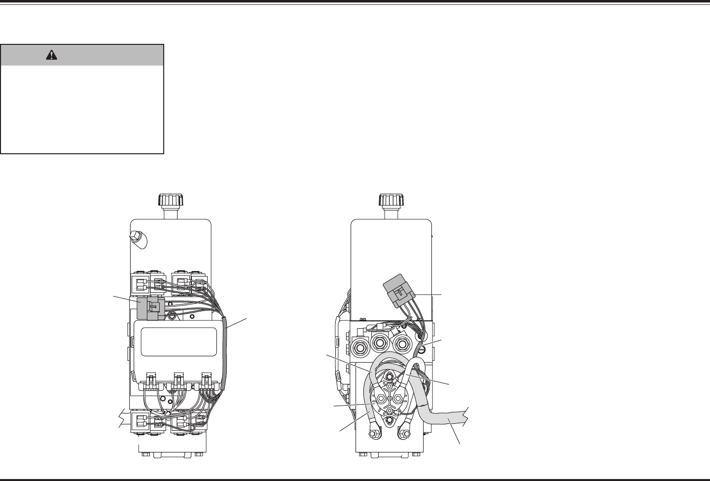
Lit. No. 27366, Rev. 01 February 15, 2008
80
TROUBLESHOOTING GUIDE
WARNING
Keep 8' clear of the blade when
it is being raised, lowered or
angled. Do not stand between
the vehicle and blade or
directly in front of the blade. If
the blade hits or drops on you,
you could be seriously injured.
Perform this test if the control lights
up and/or turns ON, but the motor
does not run.
1. Check the motor relay fuse on
harnesses B. Replace if fuse is
blown, then retest snowplow.
2. Remove the coil fuse F1 in
harness B and the coil fuses F1
and F2 in harness C of the Plow
Module. Remove the 8" red
battery cable from the large
terminal of the motor relay and
isolate it. Removing the fuses
and isolating the battery cable
will eliminate the potential of
accidental blade movement
during testing.
3. Check for 12V at the small
terminal of the motor relay with the
red wire attached to it. If 12V is not
present, recheck the coil fuse F2
in harness B. If the fuse is good,
check the red wire and harness B.
Replace/repair either the wire or
the harness as needed.
4. If 12V is present at the small
relay terminal with the red wire,
turn the control ON, then check
for switched ground on the small
terminal with the black wire
attached to it while activating any
function except LOWER. If
switched ground is not present,
check the black wire and
harness B of the Plow Module.
Replace/repair either the wire or
the harness as needed.
5. Check for switched 12V at the
empty large motor relay terminal
while activating any control
function except LOWER. The
empty terminal is the terminal
that would normally contain the
8" red battery cable. If switched
12V is not present, replace the
motor relay.
6. If switched 12V is present at the
empty large motor relay terminal,
replace the motor.
7. Once testing is complete,
reinstall fuses and 8" red battery
cable, then retest snowplow.
MOTOR AND MOTOR RELAY TEST
* See wire stamping for fuse identification.
Harness C
C
B
A
Harness C
Fuse Holder
(Remove F1 & F2.*)
Plow Module
S5S4 S6 S7
S9
S8 S10 S11
Plow
Battery Cable
Harness B
8" Red Cable
Harness B
Fuse Holder
(Remove F1.*)
Black
Red
S1 S2 S3
Motor Relay
+
-

Lit. No. 27366, Rev. 01 February 15, 2008
81
PUMP PRESSURE TEST
NOTE: Reservoir will contain
residual pressure. Remove, then
reinstall, breather to release
pressure before proceeding.
1. Verify proper fluid level before
beginning test.
2. Attach a 3000 psi hydraulic
pressure gauge to pressure test
port as shown in the illustration.
3. Activate the right retract function
until blade is fully retracted.
NOTE: Control will time out after
3 seconds. Repeat command if
blade is not fully retracted.
4. Repeat the right retract function,
and read the pressure shown on
the gauge.
5. Refer to the following table.
MOVEMENT
BLADE
RIGHT
RETRACT
MOTOR M ON
Pump Pressure
Test Port
Pump Relief
Adjustment Valve
Adapter*
Hose
Pressure
Gauge
90° Elbow**
(if required)
NOTE: See the following page for Relief Valve Inspection and
Adjustment instructions.
CONDITION
POSSIBLE
CAUSE
CORRECTIVE ACTION
• Pump relief valve may be out of
adjustment. Turn relief valve
clockwise 1/4 turn and retest
pressure. Repeat until correct
pressure (2250 ± 50 psi) is obtained.
Pump Relief
Valve
• If correct pressure is not obtained
after readjustment, remove and
inspect the relief valve and its
components. Check O-ring, stem and
ball for wear or damage. Reseat ball
or replace relief valve as needed.
Reinstall/replace and readjust valve,
then retest pump pressure.
O-Ring
(between pump
and valve block)
• Remove the pump and inspect the
O-ring between the pump and the
valve block for wear or damage.
Reinstall/replace O-ring and pump,
then retest pump pressure.
Pump pressure
is below
2250 ± 50 psi.
Pump
• Remove the pump and inspect it for
wear or broken gears. Replace pump
if needed, adjust pump relief valve,
then retest pressure.
Motor draws
more than
265 Amps at
pump relief.
Motor • Replace the motor.
* Straight Adapter (-6 JIC 37° Male Flare to -4 SAE O-Ring Boss Port) not included in 56679 Pressure Test Kit. (Parker PN 6-4 F50X)
** 90° Elbow (-6 JIC 37° Female Swivel to -6 JIC 37° Male Flare) not included in 56679 Pressure Test Kit. (Parker PN 6 C6X)
TROUBLESHOOTING GUIDE

Lit. No. 27366, Rev. 01 February 15, 2008
82
TROUBLESHOOTING GUIDE
Inspection
1. Remove the valve stem, ball,
spacer and spring.
2. Look for broken or damaged
parts, contamination or missing
or damaged O-rings.
3. If parts are OK, place ball on
hard wood block, hold stem seat
on ball and lightly strike top of
stem with a hammer. This will
seat the ball and valve stem.
4. Apply a light coat of anti-seize or
grease to stem threads.
Lubricate O-rings with hydraulic
fluid. Reassemble components
into valve block.
CAUTION
Be careful to strike stem
squarely. You can bend stem if
you do not strike it squarely.
CAUTION
Never operate the unit while
adjusting the relief valve.
Doing so will damage the relief
valve O-rings.
Adjustment
1. Screw stem in until spring is fully
compressed.
2. Back out (counterclockwise) the
number of turns in the following
chart.
RELIEF VALVE INSPECTION AND ADJUSTMENT
Relief valves B and components are not interchangeable with A and C. The
stem is marked with a drill point in the screwdriver slot for identification.
Assembly A & C
1/4" Ball
.125 Ø Hole
Valve Stem
Seat
O-Rings
Spring
Spacer
Valve Stem
Assembly B
Drill Point
Identification
Mark
7/32" Ball
.115 Ø Hole
Valve Stem
Seat
O-Rings
Spring
Spacer
Valve Stem
PS
B
Base-End
Relief Valves
C
Pump Relief Valve
Pressure
Test Port
DS
A
Rod-End
Relief Valves
PS
DS
A (Qty 2)
B (Qty 4)
C (Qty 1)
1-1/4
1-1/4
2-1/2
3700
4600
2250*
Relief
Valve
Approx.
Pressure
(psi)
# of Turns
Out (ccw)
from
Fully Seated
* See the Pump Pressure Test
Section for details.

Lit. No. 27366, Rev. 01 February 15, 2008
83

Lit. No. 27366, Rev. 01 February 15, 2008
84
A DIVISION OF DOUGLAS DYNAMICS, L.L.C.
Copyright © 2008 Douglas Dynamics, L.L.C. All rights reserved. This material may not be reproduced or copied, in whole or in part, in any printed, mechanical, electronic, film or other distribution and storage
media, without the written consent of Western Products. Authorization to photocopy items for internal or personal use by Western Products outlets or snowplow owner is granted.
Western Products reserves the right under its product improvement policy to change construction or design details and furnish equipment when so altered without reference to illustrations or specifications
used. Western Products or the vehicle manufacturer may require or recommend optional equipment for snow removal. Do not exceed vehicle ratings with a snowplow. This product is manufactured under the
following US patents: 4,999,935; 5,420,480; 6,145,222; 6,209,231; 6,253,470; 6,526,677; 6,928,757; RE 35,700; CAN patents 2,060,425; 2,354,257 and other patents pending. Western Products offers a
limited warranty for all snowplows and accessories. See separately printed page for this important information. The following are registered (
®
) or unregistered (™) trademarks of Douglas Dynamics, L.L.C.: FloStat
®
,
MVP PLUS™, NIGHTHAWK™, UltraMount
®
, WESTERN
®
.
Printed in U.S.A.
WESTERN PRODUCTS
P.O. BOX 245038
MILWAUKEE, WI 53224-9538
www.westernplows.com
