AISC Live Webinar Design of Reinforcement for Steel Members
Part II
Copyright © 2014
1
Thank you for joining our live webinar today.
We will begin shortly. Please standby.
Thank you.
Need Help?
Call ReadyTalk Support: 800.843.9166
AISC Live Webinars
1
Today’s audio will be broadcast through the
internet.
Alternatively, to hear the audio through the phone,
dial 800 741 4871.
International callers, dial 00+1 212 231 2909.
For additional support, please press *0 and you will
be connected to a live operator.
AISC Live Webinars

AISC Live Webinar Design of Reinforcement for Steel Members
Part II
Copyright © 2014
2
Today’s live webinar will begin shortly.
Please standby.
As a reminder, all lines have been muted. Please type any
questions or comments through the Chat feature on the left
portion of your screen.
Today’s audio will be broadcast through the internet.
Alternatively, to hear the audio through the phone, dial
800 741 4871.
International callers, dial 00+1 212 231 2909.
For additional support, please press *0 and you will be
connected to a live operator.
AISC Live Webinars
AISC is a Registered Provider with The American Institute of
Architects Continuing Education Systems (AIA/CES). Credit(s)
earned on completion of this program will be reported to AIA/CES
for AIA members. Certificates of Completion for both AIA members
and non-AIA members are available upon request.
This program is registered with AIA/CES for continuing professional
education. As such, it does not include content that may be
deemed or construed to be an approval or endorsement by the AIA
of any material of construction or any method or manner of
handling, using, distributing, or dealing in any material or product.
Questions related to specific materials, methods, and services will
be addressed at the conclusion of this presentation
AISC Live Webinars

AISC Live Webinar Design of Reinforcement for Steel Members
Part II
Copyright © 2014
3
Copyright Materials
This presentation is protected by US and International
Copyright laws. Reproduction, distribution, display and
use of the presentation without written permission of
AISC is prohibited.
© The American Institute of Steel Construction 2014
AISC Live Webinars
Design of Reinforcement for Steel Members Part II
Presented by Bo Dowswell, Ph.D., P.E.
February 13, 2014
This presentation is a continuation of the AISC live webinar, Design of
Reinforcement for Steel Members. Several topics will be discussed which affect
the strength and serviceability of reinforced steel members. Deflection of
beams with pre-load will be discussed briefly, and further information will be
provided on the design of built-up columns. Other topics include: weld design,
including the calculation of weld strength for built-up columns; how intermittent
welds affect the section properties of a built-up member; local buckling,
including the effect of stitch welds on the local buckling of plates. An example
problem will be used to illustrate some of the design principles for a composite
beam with reinforcement at the tension flange.
Course Description
6

AISC Live Webinar Design of Reinforcement for Steel Members
Part II
Copyright © 2014
4
• To learn and understand the AISC Specification strength and
serviceability requirements for designing reinforced structural steel
members.
• To gain familiarity with the deflection of beams with pre-load when
safely reinforcing steel members for structural steel buildings.
• To learn and understand material and code requirements for welding
of built-up structural steel beams and columns.
• To learn and understand the design principles for reinforcing composite
beams through the presentation of a design example.
Learning Objectives
7
8
DESIGN OF
REINFORCEMENT FOR
STEEL MEMBERS-
PART 2
Bo Dowswell, P.E., Ph.D.
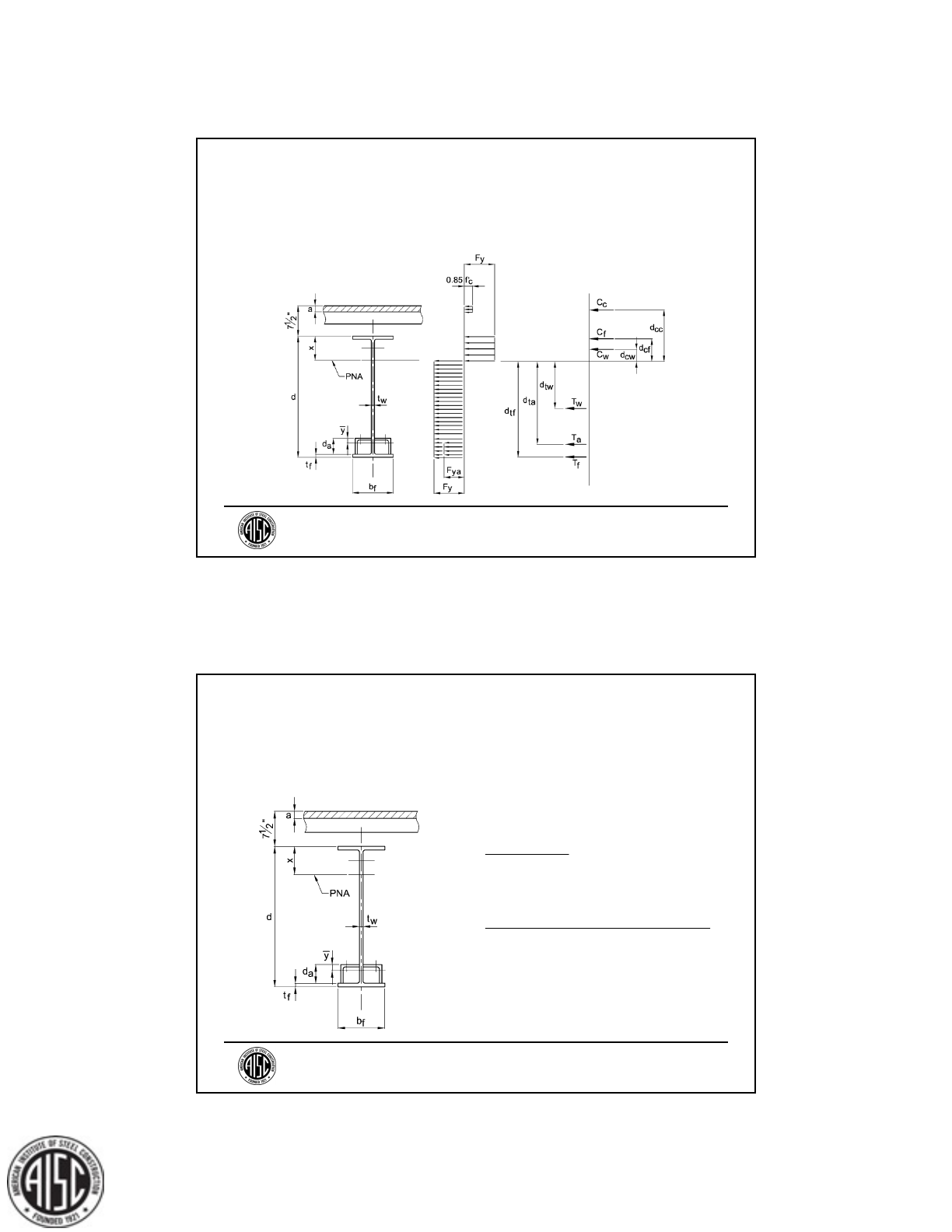
Principal
ARC International, LLC

AISC Live Webinar Design of Reinforcement for Steel Members
Part II
Copyright © 2014
5
• Reinforced Beam & Column Design
Reinforcement types
Pre-load
Partial-length reinforcement
• Course video and presentation slides are
available on the AISC Website:
www.aisc.org/content.aspx?id=37256
Part 1 Summary
9
• Beam Deflection
• Section Properties of Built-Up Members
• Weld Design
• Built-Up Columns: Additional Topics
• Flexural Plate Buckling (Plate Buckling
Between Intermittent Welds)
Course Description
10

AISC Live Webinar Design of Reinforcement for Steel Members
Part II
Copyright © 2014
6
BEAM DEFLECTION
11
Beam Deflection
Deflection of Beams with Pre-Load
• Structural analysis models are built with
reinforced member properties
• Deflection must be adjusted to account
for pre-load.
12

AISC Live Webinar Design of Reinforcement for Steel Members
Part II
Copyright © 2014
7
Pre-load deflection: deflection before
reinforcement is added.
Beam Deflection
ω
n
= proportion of load applied before the
13
Deflection of reinforced member: only
loads applied after reinforcement is added.
Beam Deflection
ω
r
= proportion of load applied after the
14

AISC Live Webinar Design of Reinforcement for Steel Members
Part II
Copyright © 2014
8
Total Deflection: =
n
+
r
n
= deflection of non-reinforced member
using loads applied before the
r
= deflection of reinforced member using
loads applied after the member is
reinforced
Beam Deflection
15
The adjusted deflection can be calculated
using the value from a finite element model
m
= total deflection from the finite element
model using the reinforced member
properties
Beam Deflection
r
mr n
n
I
I
16

AISC Live Webinar Design of Reinforcement for Steel Members
Part II
Copyright © 2014
9
I
n
= moment of inertia of non-reinforced
member
I
r
= moment of inertia of reinforced
member
Beam Deflection
17
Deflection of Beams with Partial-Length
Reinforcement
Finite Element Model
18
Beam Deflection

AISC Live Webinar Design of Reinforcement for Steel Members
Part II
Copyright © 2014
10
SECTION PROPERTIES OF
BUILT-UP MEMBERS
19
AISC Specification Section F4
Equations F4-5 and F4-8 require the
calculation of J
2
2
2
1 0.078
bb
cr
xc o t
bt
CE L
J
F
Sh r
Lr
AISC Specification
20

AISC Live Webinar Design of Reinforcement for Steel Members
Part II
Copyright © 2014
11
Torsion Constant
The torsion constant, J, can be calculated
based on individual element behavior or
integral element behavior
individual behavior integral behavior
21
Torsion Constant
Individual Element Behavior (1 Plate)
J
s
= J
w
+ J
p
J
w
= torsion constant of the W shape
J
p
= torsion constant of the plate
t
p
= plate thickness
b
p
= plate width
3
1
3
ppp
Jbt
22

AISC Live Webinar Design of Reinforcement for Steel Members
Part II
Copyright © 2014
12
Torsion Constant
Individual Element Behavior (2 Plates)
J
s
= J
w
+ J
p1
+ J
p2
J
p1
= torsion constant of Plate 1
J
p2
= torsion constant of Plate 2
23
Torsion Constant
Integral Element Behavior (1 Plate)
b = minimum of b
f
and b
p
t
f
= flange thickness
b
f
= flange width
iwp pfpf
JJ Jbtttt
24

AISC Live Webinar Design of Reinforcement for Steel Members
Part II
Copyright © 2014
13
Torsion Constant
Integral Element Behavior (2 Plates)
b
1
= minimum of b
f
and b
p1
b
2
= minimum of b
f
and b
p2
t
p1
= thickness of Plate 1
t
p2
= thickness of Plate 2
12111
22 2
iwp p pfpf
pf p f
JJ J J bttt t
bt t t t
25
Effective torsion constant for members with
intermittent welds, J
eff
J
s
< J
eff
< J
i
J
eff
= effective torsion constant
J
s
= torsion constant for independent
behavior
J
i
= torsion constant for integral behavior
Torsion Constant
26

AISC Live Webinar Design of Reinforcement for Steel Members
Part II
Copyright © 2014
14
• Generally, commercial software
packages provide J
i
• J
s
can be used as a conservative
estimate of J
eff
, but this can be extremely
conservative
• See Chang and Johnston (1952) for a
more accurate solution
Torsion Constant
27
WELD DESIGN
28

AISC Live Webinar Design of Reinforcement for Steel Members
Part II
Copyright © 2014
15
Intermittent Welds
• Lower cost
• Less weld shrinkage distortion
• Greater corrosion potential
Intermittent Welds
29
Intermittent Welds
AISC Specification Section J2.2b
• L ≥ 4w
• L ≥ 1.5 in.
L = segment length
w = weld size
30

AISC Live Webinar Design of Reinforcement for Steel Members
Part II
Copyright © 2014
16
Maximum weld spacing for intermittent welds
in AISC Specification Sections D.4 and J3.5
Intermittent Welds
1. Ensure close fit-up
over entire faying
surface
2. Prevent corrosion
between connected
elements
31
AISC Specification Sections D.4 and J3.5
(a) P
max
= 24t ≤ 12 in.
(b) Unpainted Weathering Steel:
P
max
= 14t ≤ 7 in.
P
max
= weld spacing
t = thickness of the thinner part
Intermittent Welds
32

AISC Live Webinar Design of Reinforcement for Steel Members
Part II
Copyright © 2014
17
Members Welded Under Load
Elevated temperatures near the weld cause
a reduction in material properties of the
base material
33
Welding to Loaded Members
General Recommendations
• Use small diameter electrodes and low
welding current
• Use stringer beads only (not weave
beads)
• Specify intermittent welding in short
lengths
Welding to Loaded Members
34

AISC Live Webinar Design of Reinforcement for Steel Members
Part II
Copyright © 2014
18
General Recommendations (continued)
• Where appropriate, specify a maximum
interpass temperature of 300 °F
• Allow time for welds to cool between
passes
• Use temperature crayons or other
suitable means to monitor the
temperature of the base metal near the
weld
Welding to Loaded Members
35
Welding to Loaded Members
600 °F
800 °F
1,600 °F
1,100 °F
Concept of Inactive Areas
Standard Weld Temperature Field
36

AISC Live Webinar Design of Reinforcement for Steel Members
Part II
Copyright © 2014
19
Welding to Loaded Members
600 °F
800 °F
1,600 °F
1,100 °F
Section Normal to Arc Travel
Standard Weld Temperature Field
37
Example Temperature Curve for Low Heat
Input Weld
Welding to Loaded Members
Section Through
Weld Normal to
Arc Travel
38

AISC Live Webinar Design of Reinforcement for Steel Members
Part II
Copyright © 2014
20
Example Yield Strength Curve for Low
Heat Input Weld
Welding to Loaded Members
yy
FF
Section Through
Weld Normal to
Arc Travel
39
Inactive Area Normal to Arc Travel
Conservative Values:
w
y
=1 in. for SMAW
w
y
=2 in. for FCAW
See Huenersen et al. (1990)
for a more rigorous solution
Welding to Loaded Members
40

AISC Live Webinar Design of Reinforcement for Steel Members
Part II
Copyright © 2014
21
Inactive Area Parallel to Arc Travel
Conservative Estimate:
Full flange width plus
the portion of the web
defined by w
y
See Huenersen et al. (1990)
for a more rigorous solution
Welding to Loaded Members
41
BUILT-UP COLUMNS:
ADDITIONAL TOPICS
42

AISC Live Webinar Design of Reinforcement for Steel Members
Part II
Copyright © 2014
22
How can we design the
reinforcement welds for
columns?
What are the loads?
Weld Design for Columns
43
The load in the cover plate
must be transferred to the non-
reinforced section at the
theoretical cutoff point.
Welds must develop the cover
plate’s portion of the required
axial load in the column
44
Weld Design for Columns

AISC Live Webinar Design of Reinforcement for Steel Members
Part II
Copyright © 2014
23
The load in each plate, based on equal axial
stress over the cross sectional area, is
A
p
= area of the reinforcing plate
A
r
= total area of the reinforced section
p
p
r
A
FP
A
45
Weld Design for Columns
Shear Flow
A
p
= area of the reinforcing plate
I
rx
= strong-axis moment of inertia of the
built-up member
V
r
= required shear force
v = shear force per unit length
r
rx
VQ
v
I
p
QAy
46
Weld Design for Columns

AISC Live Webinar Design of Reinforcement for Steel Members
Part II
Copyright © 2014
24
Anchor Force
rc
A
rx
M
Q
F
I
rc
M
rc
M
47
Weld Design for Columns
48
Weld Design for Columns
How can we determine V
r
and M
rc
?
Apply a uniform notional load to develop a
bending moment equal to that caused by
the initial out-of-straightness. For δ
0
=
L/1,000
P
r
= required axial load
125
r
n
P
w
L

AISC Live Webinar Design of Reinforcement for Steel Members
Part II
Copyright © 2014
25
49
Weld Design for Columns
Apply w
n
in the proper direction
The first-order moment,
M
c
, is calculated at the
theoretical cutoff point.
If the column is subjected
to axial load only, the
maximum shear, V
r
, is at
the theoretical cutoff
point.
Weld Design for Columns
50

AISC Live Webinar Design of Reinforcement for Steel Members
Part II
Copyright © 2014
26
AISC Manual Table 3-23,
Case 1.
51
2
x
wx
M
lx
2
x
l
Vw x
Weld Design for Columns
The required moment, M
rc
, can be determined
with a second order analysis or calculated using
multiplier, B
1
from AISC Specification
Appendix 8, Section 8.2.
1
1
1 α
m
r
e
C
B
P
P
1rc c
M
BM
Weld Design for Columns
52

AISC Live Webinar Design of Reinforcement for Steel Members
Part II
Copyright © 2014
27
P
e1
= elastic lateral buckling load of the
column
P
r
= required axial strength
C
m
= 1.0
= 1.00
for LRFD
= 1.60 for ASD
Weld Design for Columns
53
p
p
r
A
FP
A
The total load in the plate at the theoretical
cutoff point is the anchor force for the
moment plus the plate’s portion of the axial
load.
54
Weld Design for Columns
rc
A
rx
M
Q
F
I
rpA
F
FF

AISC Live Webinar Design of Reinforcement for Steel Members
Part II
Copyright © 2014
28
F
r
must be developed
over distance,
d
rt
The shear force per unit
length,
v, must me
developed between the
theoretical cutoff points
Weld Design for Columns
55
FLEXURAL PLATE
BUCKLING
56

AISC Live Webinar Design of Reinforcement for Steel Members
Part II
Copyright © 2014
29
Column Local Buckling
b
t
140
r
y
E
F
.
Column Flange Plates
Specification Table B4.1a, Case 7
57
Beam Local Buckling
b
t
140
r
y
E
F
.
112
p
y
E
F
.
Beam Compression Flange Plates
Specification Table B4.1b, Case 18
58

AISC Live Webinar Design of Reinforcement for Steel Members
Part II
Copyright © 2014
30
Flexural Plate Buckling
Flexural Buckling Between Intermittent
Welds
Local Buckling Flexural Buckling
59
AISC Specification Section E6.2
Non-Staggered:
t = plate thickness
075 12in.
max
y
E
Pt
F
.
Flexural Plate Buckling
60

AISC Live Webinar Design of Reinforcement for Steel Members
Part II
Copyright © 2014
31
The buckled shape of the plate changes
when staggered welds are used
Flexural Plate Buckling
61
AISC Specification Section E6.2
Staggered:
50% increase in
P
max
when staggered
1 12 18 in.
max
y
E
Pt
F
.
Flexural Plate Buckling
62

AISC Live Webinar Design of Reinforcement for Steel Members
Part II
Copyright © 2014
32
Norris et al. (1951) found critical C/b ratios,
where local buckling will be the controlling
limit state If
C/b < (C/b)
cr
.
Flexural Plate Buckling
C = clear distance
between fasteners
b = plate width
63
For Stiffened Elements,
For Unstiffened Elements,
Flexural Plate Buckling
050
cr
C
b
.
14
cr
C
b
.
64

AISC Live Webinar Design of Reinforcement for Steel Members
Part II
Copyright © 2014
33
140
r
y
bE
tF
.
05 05 070
rr r
y
E
Cbt t
F
.. .
Beam Compression Flange Plates
050
cr
C
b
.
For Stiffened Elements
Specification Table
B4.1b, Case 18
Flexural Plate Buckling
65
112
p
y
bE
tF
.
05 05 056
pp p
y
E
Cbt t
F
.. .
Beam Compression Flange Plates
Specification Table
B4.1b, Case 18
Flexural Plate Buckling
66

AISC Live Webinar Design of Reinforcement for Steel Members
Part II
Copyright © 2014
34
14
cr
C
b
.
For Unstiffened
Elements
14
rr
Ct.
14
p
p
Ct.
Select
r
and
p
from AISC
Specification Table B4.1a or
B4.1b.
Flexural Plate Buckling
67
COMPOSITE BEAM
EXAMPLE
68

AISC Live Webinar Design of Reinforcement for Steel Members
Part II
Copyright © 2014
35
An existing composite beam must carry an
additional live load of 40 psf. This example
shows calculations for the required
reinforcement using LRFD.
For the existing beam calculations, see
Example I.1 in the AISC Design Examples,
Version 14.1.
69
70

AISC Live Webinar Design of Reinforcement for Steel Members
Part II
Copyright © 2014
36
71
72

AISC Live Webinar Design of Reinforcement for Steel Members
Part II
Copyright © 2014
37
Given:
The live load increased from 100 psf to 140
psf.
The existing live load will be removed
before the beam is reinforced.
The existing beam is A992.
73
For the existing beam:
The available flexural strength,
b
M
n
= 769 kip-ft
The lower bound moment of inertia,
I
LB
= 2,520 in.
4
74

AISC Live Webinar Design of Reinforcement for Steel Members
Part II
Copyright © 2014
38
The concrete is normal weight with a
specified compressive strength,
f
c
= 4 ksi.
There are 46 ¾-in.-diameter headed stud
anchors symmetrically placed about the
midspan.
The existing dead load is 0.900 kip/ft
75
Solution:
Existing Beam Material Properties
A992
F
y
= 50 ksi
F
u
= 65 ksi
76

AISC Live Webinar Design of Reinforcement for Steel Members
Part II
Copyright © 2014
39
Applied Loads
Estimated weight of reinforcement:
20 lbs/ft = 0.02 kip/ft
Dead load:
w
D
= 0.900 kip/ft + 0.02 kip/ft = 0.920 kip/ft
77
Live load:
w
L
= (10.0 ft)(140 psf)(0.001 kip/lb)
= 1.40 kips/ft
Required load:
w
u
= (1.2)(0.920 kip/ft) + (1.6)(1.40 kip/ft)
= 3.34 kips/ft
78

AISC Live Webinar Design of Reinforcement for Steel Members
Part II
Copyright © 2014
40
Required Flexural Strength
AISC Manual Table 3-23, Case 1.
79
2
2
8
3.34 kip/ft 45.0 ft
8
845 kip-ft
u
u
wL
M
80
Preliminary Analysis Conclusions
For the existing beam,
b
M
n
= 769 kip-ft
769 kip-ft < 845 kip-ft
(Utilization Ratio = 1.10)
> L/360 (18% Over)
The beam must be reinforced

AISC Live Webinar Design of Reinforcement for Steel Members
Part II
Copyright © 2014
41
Reinforcement Selection Issues
• Flexural reinforcement is most efficient
when located farthest from the neutral
axis
• Partial-length reinforcement is more
economical than full-length
reinforcement
81
Horizontal Overhead
Reinforcement Selection Issues (continued)
• Productivity for horizontal welding is
about 4 times that of overhead welding
82

AISC Live Webinar Design of Reinforcement for Steel Members
Part II
Copyright © 2014
42
Reinforcement Selection Issues (continued)
• An adequate shelf dimension must be
provided for fillet welds
• For this example, the bottom of the beam
must remain clear of obstructions
83
Two L 2 ½ 2 ½ 3/8 will be added to the
top of the bottom flange. The material will
be A36 (
F
y
= 36 ksi, F
u
= 58 ksi).
84
L 2 ½ 2 ½ 3/8 :
A
a
= 1.73 in.
2
I
xa
= 0.972 in.
4
y = 0.758 in.

AISC Live Webinar Design of Reinforcement for Steel Members
Part II
Copyright © 2014
43
The total weight of the reinforcement is
(2)(5.90 lb/ft) = 11.8 lb/ft = 0.0118 kip/ft
The revised load is
w
u
= 1.2(0.912 kip/ft) + 1.6(1.40 kip/ft)
= 3.33 kips/ft
The revised moment, M
u
= 844 kip-ft.
85
Available Flexural Strength
AISC Specification Section I3.2a: Plastic
stress distribution shall be used when
The stabilizing effect of the reinforcing
angles will be neglected.
86
3.76
wy
hE
tF

AISC Live Webinar Design of Reinforcement for Steel Members
Part II
Copyright © 2014
44
From AISC Manual Table 1-1, h/t
w
for a
W21
50 is 49.4.
49.4 < 90.6; therefore, the plastic stress
distribution will be used.
87
29,000 ksi
3.76 3.76 90.6
50 ksi
y
E
F
Concrete Strength
A
c
= (120 in.)(4.5 in.)
= 540 in.
2
C = 0.85f
c
A
c
= (0.85)(4 ksi)(540 in.
2
)
= 1,840 kips
88

AISC Live Webinar Design of Reinforcement for Steel Members
Part II
Copyright © 2014
45
Steel Strength
T = A
s
F
y
= (50 ksi)(14.7 in.
2
) + (2) (36 ksi)(1.73
in.
2
)
= 860 kips
89
Steel Anchor Strength
AISC Manual Table 3-21
Assume all anchors are placed in the weak
position
1 anchor per rib:
Q
n
= 17.2 kips/anchor
2 anchors per rib: Q
n
= 14.6 kips/anchor
90

AISC Live Webinar Design of Reinforcement for Steel Members
Part II
Copyright © 2014
46
Q
n
= (2)(14.6 kips/anchor)
+ (21)(17.2 kips/anchor)
= 390 kips
The compression load in the concrete is
C = MIN(1,840, 860, 390) = 390 kips
Shear transfer for composite action is
controlled by the anchor strength.
91
AISC Specification Section I3.1a
The effective width of the concrete slab is
the minimum of
(1) One eighth of the beam span
b
e1
= (45 ft.)(2 sides)/8 = 11.3 ft
92

AISC Live Webinar Design of Reinforcement for Steel Members
Part II
Copyright © 2014
47
(2) One-half the distance to the centerline
of the adjacent beam
b
e2
= (10 ft.)(2 sides)/2 = 10.0 ft
(3) Distance to the Edge of the slab
Not Applicable
93
The effective width of slab is
b
e
= b
e2
= 10.0 ft = 120 in.
94
b
e
= 10.0 ft
AISC Live Webinar Design of Reinforcement for Steel Members
Part II
Copyright © 2014
48
Plastic Analysis of Cross Section
95
Compression Block Depth
96
0.85
390 kips
0.85 4 ksi 120 in.
0.956 in.
c
C
a
fb

AISC Live Webinar Design of Reinforcement for Steel Members
Part II
Copyright © 2014
49
C
c
= 390 kips
C
f
= (50 ksi)(0.535 in.)(6.53 in.) = 210 kips
T
f
= (50 ksi)(0.535 in.)(6.53 in.) = 210 kips
T
a
= (2 angles)(36 ksi)(1.73 in.
2
) = 125 kips
C
w
= (50 ksi)(0.380 in.)(x 0.535 in.)
T
w
= (50 ksi)(0.380 in.)(20.8 in. 0.535 in. x)
97
The plastic neutral axis (PNA) is located by
force equilibrium
C = T
C
c
+ C
f
+ C
w
= T
f
+ T
a
+ T
w
Solve for x = 3.44 in.
Also: C
w
= 55.3 kips
T
w
= 320 kips
98

AISC Live Webinar Design of Reinforcement for Steel Members
Part II
Copyright © 2014
50
d
cc
= 3.44 in. + 7.50 in. 0.956 in./2 = 10.5 in.
d
cf
= 3.44 in. 0.535 in./2 = 3.17 in.
d
cw
= (3.44 in. 0.535 in.)/2 = 1.45 in.
d
tf
= 20.8 in. 3.44 in. 0.535 in./2 = 17.1 in.
99
d
ta
= 20.8 in. 3.44 in. 0.535 in. 2.50
+ 0.758 in.
= 15.1 in.
d
tw
= (20.8 in. 3.44 in. 0.535 in.)/2 = 8.41 in.
100

AISC Live Webinar Design of Reinforcement for Steel Members
Part II
Copyright © 2014
51
M
n
= (390 kips)(10.5 in.)
+ (210 kips)(3.17 in.)
+ (55.3 kips)(1.45 in.)
+ (320 kips)(8.41 in.)
+ (125 kips)(15.1 in.)
+ (210 kips)(17.1 in.)
= 13,010 kip-in.
= 1,080 kip-ft.
101
b
M
n
= (0.90)(1,080 kip-ft)
= 972 kip-ft
M
u
= 844 kip-ft. < 972 kip-ft o.k.
102

AISC Live Webinar Design of Reinforcement for Steel Members
Part II
Copyright © 2014
52
Required Shear Strength
AISC Manual Table 3-23, Case 1.
103
2
3.33 kips/ft 45.0 ft
2
74.9 kips
u
u
wL
V
Available Shear Strength
AISC Specification Section I4.2
The available shear strength is based on
the properties of the steel section alone
AISC Manual Table 3-2
v
V
n
= 237 kips > 74.9 o.k.
104

AISC Live Webinar Design of Reinforcement for Steel Members
Part II
Copyright © 2014
53
Location of the Theoretical Cutoff Point
Only partial-length reinforcement will be
provided. The location of the theoretical
cutoff point must be determined so the
flexural strength of the non-reinforced
segments will be adequate.
105
AISC Manual Table 3-23, Case 1.
For the existing beam,
b
M
n
= 769 kip-ft.
l= 45 ft
w
u
= 3.33 kips/ft
106

AISC Live Webinar Design of Reinforcement for Steel Members
Part II
Copyright © 2014
54
Solve for x = 15.5 ft
Use a preliminary distance from the end of
the beam to the theoretical cutoff point of
14 ft.
107
2
3.33 kips/ft
769 kip-ft 45.0 ft
2
x
wx
Mlx
x
x
Live Load Deflection
Live load deflection will be limited to:
1. For 100% of the design live load:
a
= L/360 = (45 ft)(12 in./ft)/360 = 1.50
in.
2. For 50% of the design live load:
a
= 1.0 in.
108

AISC Live Webinar Design of Reinforcement for Steel Members
Part II
Copyright © 2014
55
109
n
equiv s tr s
f
Q
IIII
C
Deflection will be calculated using I
eff
AISC Specification Commentary Section I3.2
I
eff
= 0.75I
equiv
AISC Specification Commentary Equation C-
I3-4
Transformed Moment of Inertia
= E
s
/E
c
= (29,000 ksi)/(3,490 ksi)
= 8.31
b
tr
= (10 ft)(12 in./ft)/8.31
= 14.4 in.
I
tr
= 5,500 in.
4
110

AISC Live Webinar Design of Reinforcement for Steel Members
Part II
Copyright © 2014
56
The moment of inertia of the structural
steel section, including the reinforcing
angles,
I
s
= 1,170 in.
4
111
Q
n
= 390 kips
T = A
s
F
y
= 860 kips
C = 0.85f
c
A
c
= 1,840 kips
C
f
= compression force in slab for fully
composite beam
= minimum of T and C
= 860 kips
112

AISC Live Webinar Design of Reinforcement for Steel Members
Part II
Copyright © 2014
57
113
444
4
in. 5 500 i
390 kips
1 170 1 1n. in.70
860 kip
i
s
4 090 n.
n
equiv s tr s
f
Q
IIII
C
,,
,
,
AISC Specification Commentary Equation
C-I3-4
AISC Specification Commentary Section
I3.2
I
eff
= 0.75I
equiv
= (0.75)(4,090 in.
4
)
=3,070 in.
4
114

AISC Live Webinar Design of Reinforcement for Steel Members
Part II
Copyright © 2014
58
For 100% live load
Using a three-member stepped beam finite
element model with:
w
L
= 1.40 kips/ft
L
r
= 18.3 ft
d
r
= 13.3 ft
E = 29,000 ksi
115
I
1
= 3,070 in.
4
I
2
= 2,520 in.
4
c
= 1.58 in. > 1.50 n.g.
116
I
1
I
2
I
2

AISC Live Webinar Design of Reinforcement for Steel Members
Part II
Copyright © 2014
59
Options to Limit Deflection
•Calculate
I using a more rigorous
approach
• Increase
I
1
by changing the angle size
• Increase the length of reinforcement,
L
r
117
Using the three-member stepped beam
finite element model with:
L
r
= 39 ft
d
r
= 3 ft
c
= 1.48 in. < 1.50 o.k.
118

AISC Live Webinar Design of Reinforcement for Steel Members
Part II
Copyright © 2014
60
For 50% live load
Using the three-member stepped beam
finite element model with:
w
L
= 0.70 kips/ft
L
r
= 39 ft
d
r
= 3 ft
c
= 0.73 in. < 1.0 o.k.
119
Welds at the End of the Reinforcement
120
rc
M
rc
M

AISC Live Webinar Design of Reinforcement for Steel Members
Part II
Copyright © 2014
61
The anchor force is
However, this equation is valid only in the
elastic range, where
M
r
≤ M
y
M
y
= F
y
S
x
rc
A
rx
M
Q
F
I
121
Due to the approximate nature of the
moment of inertia calculations, the weld
will be designed to develop the available
strength of the angles.
122
2
0 9 36 ksi 1 73 in. 56 0 kips
bn
P ...

AISC Live Webinar Design of Reinforcement for Steel Members
Part II
Copyright © 2014
62
Use two 3/16 in. fillet welds extending 8 in.
beyond the theoretical cutoff point. For
concentrically loaded weld groups, AISC
Manual Equation 8-2a is applicable.
w
R
n
= 1.39Dl
= (1.39)(3)[(2 welds)(8 in.)]
= 66.7 kips > 56.0 kips
o.k.
123
The beam web bust be thick enough to
transmit the load from the angles from the
beam. AISC Manual Equation 9-3 is
applicable.
0.286 in. < 0.380 in. o.k.
124
619 3
619
0 286 in.
65 ksi
min
u
D
t
F
.
.
.

AISC Live Webinar Design of Reinforcement for Steel Members
Part II
Copyright © 2014
63
Final Weld Design
125
Questions?
Bo Dowswell, P.E., Ph.D.
Principal
ARC International, LLC
126

AISC Live Webinar Design of Reinforcement for Steel Members
Part II
Copyright © 2014
64
References
Chang, F.K. and Johnston, B.G. (1952), “Torsion of Plate Girders,”
Transactions, American Society of Civil Engineers, April.
Huenersen, G., Haensch, H. and Augustyn, J. (1990), “Repair Welding
Under Load,” Welding in the World, Vol. 28, No. 9/10, pp. 174-182.
Norris, C.H., Polychrome, D.A. and Capozzoli, L.J. (1951), “Buckling
of Intermittently Supported Rectangular Plates,” Welding Research
Supplement, American Welding Society, November, pp. 546-s through
556-s.
127
Within 1 business day…
• You will receive an email on how to report attendance
from: [email protected]
• Be on the lookout: Check your spam filter! Check
your junk folder!
• Completely fill out online form. Don’t forget to check
the boxes next to each attendee’s name!
OR…
CEU Certificates

AISC Live Webinar Design of Reinforcement for Steel Members
Part II
Copyright © 2014
65
Access available in 24 hours…
• Go to:
http://www.wynjade.com/aisc14/webinarceu
Username: Your Attendee ID (found on your reg. receipt)
Password: Your Last Name
• Completely fill out online form. Don’t forget to check
the boxes next to each attendee’s name!
• Questions? Please email us at [email protected].
CEU Certificates
March 13 and 20, 2014:
2-part Webinar: Structural Stainless Steel
www.aisc.org/webinars
AISC Webinars

AISC Live Webinar Design of Reinforcement for Steel Members
Part II
Copyright © 2014
66
Spring 2014 Schedule has been released!
Seismic Design Manual and Application of the 2010 Seismic
Provisions
24 cities this spring
www.aisc.org/seminars
AISC Seminars
Fundamentals of Earthquake Engineering for Building Structures
Presented by Rafael Sabelli, Walter P Moore
Class begins February 24, 2014!
www.aisc.org/nightschool
AISC Night School

AISC Live Webinar Design of Reinforcement for Steel Members
Part II
Copyright © 2014
67
Thank You
Please fill out a brief survey at the conclusion of the webinar.
Your feedback is greatly appreciated.
