
Supply Drainage Support Specialties
DETERMINING ARRESTER
SIZE BY FIXTURE UNITS
The National Plumbing Code offers
this denition of xture unit: “A xture-
unit is a quantity in terms of which the
load producing effects on the plumbing
system of different kinds of plumbing
xtures are expressed on some
arbitrarily chosen scale.” The xture
unit values shown in Table 1 below
represent the standard ratings used
by engineers to size water distribution
systems as well as water hammer
arresters. “Public” xtures, as referred
to in Table 1 below, are xtures found in
public rest rooms, ofce buildings and
other places where each xture is open
and accessible for use at all times.
MULTIPLE FIXTURE
BRANCH LINES
On many types of applications, a single
arrester must serve multiple xtures.
In these cases, the total xture units
should be determined for all xtures
served by the branch line where the
arrester is to be placed. Once the
xture units for the branch line have
been totaled, choose the appropriate
arrester by matching xture units in the
table (below) to the arrester size with
the corresponding xture unit capacity.
If the total number of xture units has
a fraction, it should be rounded to the
next largest whole number. In addition,
if the ow pressure at the xture
exceeds 65 psig, the next largest size
water hammer arrester should be used.
ARRESTER PLACEMENT ON
MULTI-FIXTURE BRANCH LINES
Once the correct size arrester has
been determined, the nal concern is
placement of the arrester within the
system. Arrester placement depends on
the length of the branch line on which
the arrester is to be installed, which
can be divided into two cases which are
described below:
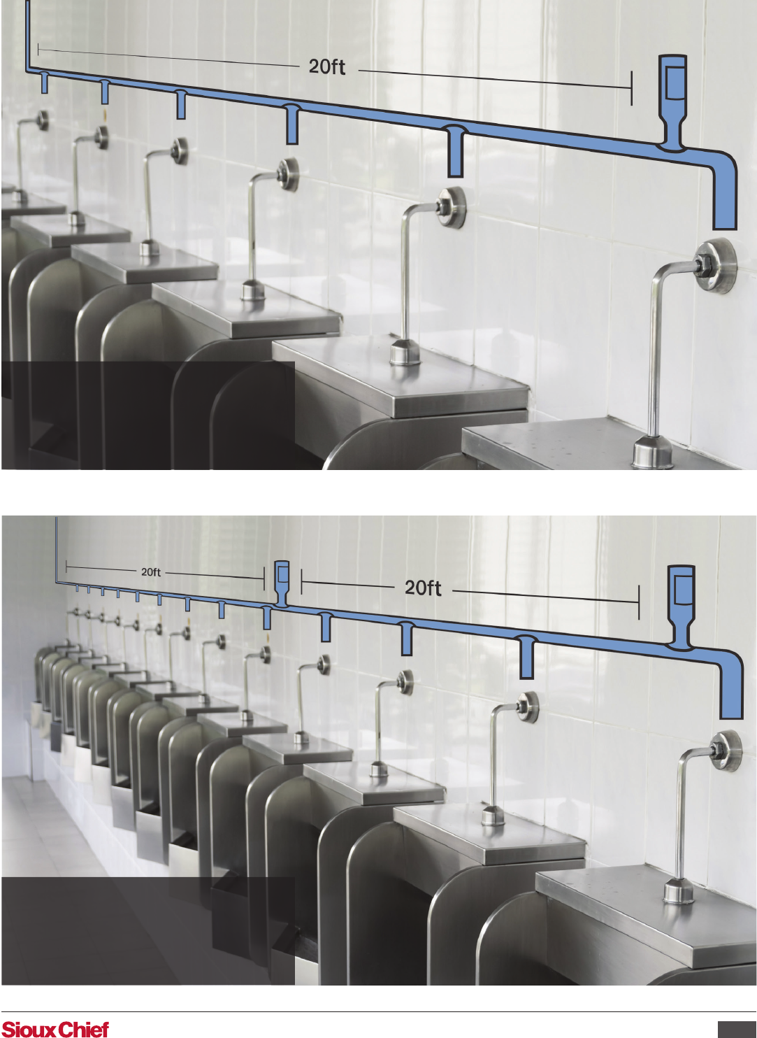
BRANCH LINES OF
20 FEET OR LESS
(See Figure 1)
Place arrester at the end of the branch
line within 6 feet of the last xture
served, as illustrated on page 15.
BRANCH LINES
OVER 20 FEET
(See Figure 2)
Calculate xture units for each 20-foot
section separately and place an arrester
at the end of each 20-foot section
(within 6 feet of the last xture served
in that section) as illustrated in Figure 2
on page 15.
The following should be used as a guide only. Always consult local plumbing codes for specic requirements before installation.
For water hammer control in commercial plumbing applications, such as water closets, urinals and lavs in public restrooms, use the
following sizing and placement guidelines based on xture units.
FIXTURE
TYPE OF SUPPLY
CONTROL
FIXTURE UNITS
PUBLIC PRIVATE
TOTAL C.W. H.W. TOTAL C.W. H.W.
Water Closet 1.66 PF Flush Valve 8 8 - 5 5 -
Water Closet 1.66 PF Flush Tank 5 5 - 2.5 2.5 -
Pedestal Urinal 1.06 PF Flush Valve 4 4 - - - -
Stall or Wall Urinal Flush Valve 4 4 - - - -
Stall or Wall Urinal Flush Tank 2 2 - - - -
Lavatory Faucet 2 1½ 1½ 1 1 1
Bathtub Faucet 4 2 3 2 1½ 1½
Shower Head Mixing Valve 4 2 3 2 1 2
Bathroom Group Flush Valve Closet - - 8 8 3
Bathroom Group Flush Valve Closet - - 6 6 3
Separate Shower Mixing Valve - - 2 1 2
Service Sink Faucet 3 3 3 - - -
Laundry Tubs (1-3) Faucet - - - 3 3 3
Combination Fixture Faucet - - - 3 3 3
Clothes Washer Solenoid Valves - - - 4 3 3
Dishwasher Solenoid Valve - - - 1.5 - 1.5
Ice Maker Solenoid Valve - - - 1 1 -
ARRESTER SIZE AA A B C D E F
FIXTURE UNITS 1-4 5-11 12-32 33-60 61-113 114-154 155-300
TABLE 1
TABLE 2
Sizing & Placement Guideline
Sioux Chief Manufacturing Company | P: 1.800.821.3944 | F: 1.800.758.5950 | www.siouxchief.com
01-23
FIGURE 1
If 20ft or less, place one arrester
6ft or less from the end of the run.
FIGURE 2
If more than 20ft, place arrester at the
end of each 20-foot section, within 6ft
of the end of that section.
